3 minute read
Description of function


Description of function
402275
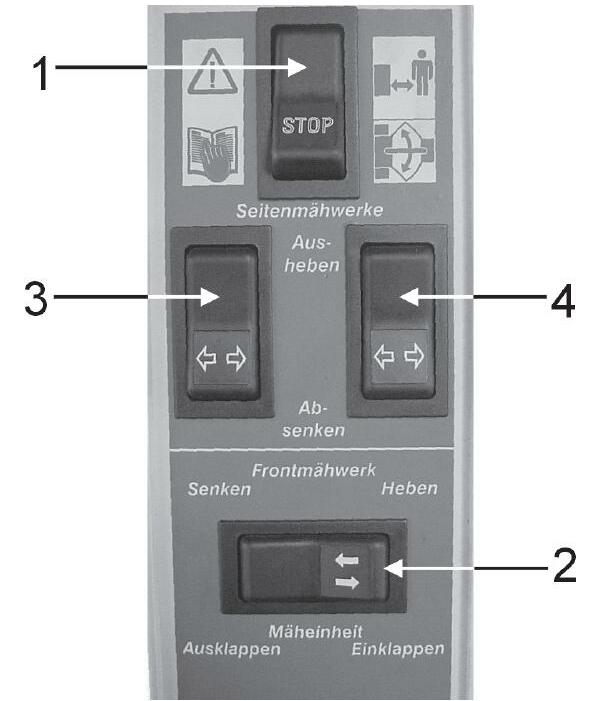
Putting into operation Switch on stop switch 1. Current is applied to all relays, terminal 86 and to the solenoid valves Raising the left Disco Actuate rocker switch 3. Earth is connected to pin 7 of connector 7. Earth is connected with relay 14 at terminal 85 and to the solenoid valve 73. Relay 14 connects earth to the 4/3-way valve 50B. Lowering the left Disco Actuate rocker switch 3. Earth is connected to pin 8 of connector 7. Earth is connected with relay 13 at terminal 85 and to the solenoid valve 73. Relay 13 connects earth to the 4/3-way valve 50A. Raising the right Disco Actuate rocker switch 4. Earth is connected via pin 9 of connector 7 to relay 14, terminal 85 and to the solenoid valve 74. Relay 14 connects earth to the solenoid valve 50. This valve switches to position B. Lowering the right Disco Actuate rocker switch 4.Earth is connected via pin 10 of connector 7 to relay 13, terminal 85 and to the solenoid valve 74. Relay 13 connects earth to the solenoid valve 50. This valve switches to position A.
Moving the Disco to working position Actuate rocker switch 2.Earth is connected via pin 2 of connector 7 to relay 13, terminal 85 and to the solenoid valves 70 and 71. Relay 13 connects earth to the solenoid valve 50. This valve switches to position A. The mower unit swings out. When reaching the end position and 150 bar, the oil pressure switch 95 connects earth to the solenoid valve 72. By means of the energised solenoid valve 72, the front mower unit is lowered.
Moving the Disco to transport position Actuate rocker switch 2. Earth is connected via pin 1 of connector 7 to relay 14, terminal 85 and to solenoid valve 72. Relay 14 connects earth to the solenoid valve 50. This valve switches to position B. The centre mower unit is raised.When reaching the end position and 150 bar, the oil pressure switch 93 connects earth to the solenoid valves 70 and 71. The mower units swing in.
Blocking the accumulator when raising the entire mower unit (quick raising) When the 3/3-way raise front attachment solenoid valve is energised by the chopper, the Reed switch*75 connects earth to relay 15, terminal 85 and relay 12, terminal 85. Relay 15 cuts the current to the lock-up valve unit 109. Relay 12 also cuts the current to the lock-up valve units 89 and 99 (the lockup valve unit are closed when de-energised). When the raise process is finished, there is a pressure of > 85 bar in the cylinders of the Jaguar front attachment due to the weight of the mower units.The oil pressure switch 94 connects earth to relay 12, terminal 85, provided the pressure in the raise cylinders is > 80 bar. Relay 12 switches and cuts the power supply to the lock-up valve units 89, 99 and 109. This is necessary to ensure that when raising the mower units on the turning area, they remain in their position when the raise process is complete. When the pressure rises above 140 bar in the cylinders 90 and 100, the oil pressure switches 96 open briefly. The earth at relay 12, terminal 85 drops and the relay connects current to the lock-up valve units 89 and 99. The lock-up valve units open and the accumulators receive oil from the piston rod ends (from the front attachment cylinders on the Jaguar) so that there will be no oil losses and/or no oil can flow from the system into the tank (pressure relief valve 104). * On the Jaguar 800, the Reed switch switches earth. On the Jaguar 600, earth is provided directly from the 3/3-way "Raise" solenoid valve