8 minute read
Rear Suspension

REAR ARM SPRING TENSION The rear spring tension is adjusted for the weight of the driver. Three possible adjustments exist: 1st block position — light operator 2nd block position — medium operator 3rd block position — heavy operator This section has been organized so each procedure can be completed individually and efficiently. The technician should use discretion and sound judgment when removing and installing components.
Removing Skid Frame
NOTE: Many service procedures can be performed
without removing the skid frame. Closely observe the note introducing each subsequent sub-section for this important information.
1.Loosen the jam nuts and the two track tension adjusting cap screws.
744-947A
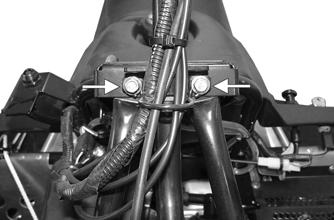
2.Place a support stand under the rear bumper; then remove the two cap screws securing the upper idler wheel assembly to the tunnel. NOTE: The support stand should hold the snowmo-
bile level and not raised off the floor.
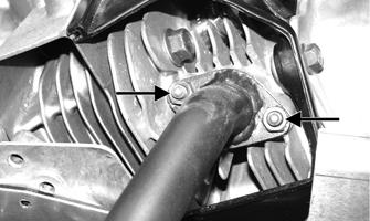
3.Remove the cap screws securing the front axle, idler axle, and rear suspension arm to the tunnel.

IO115B
4.Remove the support stand; then tip the snowmobile onto its left side using a piece of cardboard to protect against scratching. Remove the skid frame assembly.
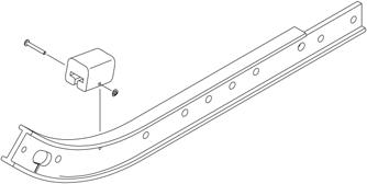
End Cap
REMOVING 1.Remove the lock nut, washers, and cap screw securing the end cap.

SNO-973
2.Using a hammer, tap the end cap off the rail. CLEANING AND INSPECTING 1.Inspect the end cap area of the slide rail for cracks and wear. 2.Inspect the end cap for any signs of cracking or wear. 3.Clean both the slide rail area and the end cap. Using compressed air, clean the areas of dirt and gravel.
4.Inspect the cap screw for cracked, stretched, or damaged threads. Use a new lock nut when assembling. INSTALLING 1.Position the end cap on the slide rail; then align the hole in the end cap with the hole in the slide rail. 2.Secure with a cap screws, washers, and new lock nut.
Tighten to 80 in.-lb.
! WARNING
Always wear safety glasses when using compressed air.
Wear Strip
REMOVING NOTE: Prior to removing the wear strips, inspect
each wear strip for wear. The wear strip must be a minimum of 0.42” thick. If the wear strip measurement is less than specified, replacement of both wear strips is necessary.
1.With the skid frame removed, remove the machine screw and lock nut securing the wear strip to the front of the slide rail.

SNO-978
2.Align the wear strip with the openings (windows) in the track; then using a suitable driving tool, drive the wear strip rearward off the slide rail. CLEANING AND INSPECTING 1.Clean the slide rail using parts-cleaning solvent and compressed air.
2.Inspect the slide rail for cracks. If any cracks are found, replace the slide rail. 3.Using a straightedge, inspect the slide rail for any unusual bends. Place the straightedge along the bottom surface of the slide rail. If the rail is found to be bent, it must be replaced. 4.Place the straightedge along the side of the slide rail.
If rail is found to be bent, it must be replaced. INSTALLING NOTE: Use a file to remove any sharp edges on the
lower portion of the rail.
1.Align the wear strip with the openings (windows) in the track and from the back, start the wear strip onto the rail; then using a block of wood and a hammer, drive the wear strip forward into position. 2.Secure with a machine screw and lock nut. Tighten to 50 in.-lb. ! WARNING
Always wear safety glasses while using compressed air.
Rear Suspension Arm/Rear Springs
DISASSEMBLING 1.With the skid frame removed, remove the cap screws securing the rear arm to the support bracket and rail; then remove the rear arm. Account for and note the location of all hardware.
2.Remove the rear springs and sleeves from the rear arm. INSPECTING 1.Inspect all rear arm weldments for cracks or unusual bends. 2.Inspect all tubing for cracks or unusual bends. 3.Inspect the axles for wear or damage. 4.Inspect the upper and lower bearings for wear or damage. 5.Inspect the two spring adjuster blocks for damage. 6.Inspect the springs for excessive wear, cracks, or imperfections. ASSEMBLING 1.Apply a light coat of grease to the axles and the bushing areas. 2.Place the rear arm into position on the support bracket and rail; then secure with cap screws (threads coated with blue Loctite #243). Tighten to 20 ft-lb.
Rear Idler Wheels and Axle

744-844A
DISASSEMBLING 1.With the skid frame removed, remove the cap screws and flat washers securing the outer idler wheels.
Remove the idler wheels from the axle and account for the adjuster bushings. 2.Slide the axle out of the rear axle housing and the rear spacer.
CLEANING AND INSPECTING 1.Clean the bearings with a clean cloth. 2.Inspect all idler wheel bearings. Rotate each bearing (by hand) and if any roughness or binding is noted, replace the idler wheel assembly. 3.Inspect the outer rubber portion of the idler wheels for cracks and poor bonding. 4.Inspect the plastic hub of each idler wheel for cracking. 5.Inspect the axle for wear and damaged threads. Damaged threads may be repaired with a 3/8 x 16 tap. ASSEMBLING 1.In order, slide the axle through the rear axle housing; then place a spacer on the axle. Slide the axle through the opposite axle housing. 2.Place the adjuster bushings on the axle (on the outside of each axle housing). Make sure the adjuster bushing is positioned properly toward the adjusting cap screw. 3.Place the rear idler wheels on the axle and secure with two cap screws (coated with blue Loctite #243) and washers. Tighten to 20 ft-lb.

Upper Idler Wheels
REMOVING 1.Remove the two cap screws securing the upper idler wheels to the tunnel; then remove the wheels.

SNO-972
2.Account for and note the location of all spacers. INSPECTING 1.Inspect each idler wheel for cracks or damage. 2.Rotate the idler wheel bearing (by hand) and inspect for binding or roughness. 3.Inspect the axle and spacers for cracks or bends. INSTALLING 1.Lightly grease the axle; then slide the inner spacer onto the axle. 2.Place the upper idler wheels into position, place the spacers into position, and secure with cap screws (coated with blue Loctite #243). Tighten to 20 ft-lb.
744-844A

744-844B
REMOVING NOTE: When replacing one or both slide rails is
necessary, remove one slide rail at a time. The remaining slide rail will then hold the crossbraces and brackets in their correct assembly order which is much quicker than to completely disassemble the entire skid frame.
1.With the skid frame removed, remove the cap screw, washers, and lock nut securing the end cap to the slide rail. Remove the end cap from the slide rail.
SNO-973
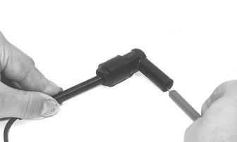
2.Remove the cap screw securing the crossbrace axle to the slide rail.
SNO-974
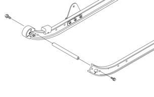
3.Remove the cap screw securing the rear suspension arm to the support bracket. 4.Remove the cap screws and lock nuts securing the rear suspension arm support bracket.
SNO-975
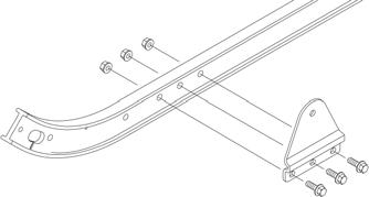
5.Remove the cap screw and washer securing the rear idler wheel to the axle. Slide the wheel off the axle and account for the adjuster bushing. 6.Remove the two cap screws and lock nuts securing the rear axle housing; then remove the housing. 7.Remove the push nut and solid rivet securing the shock pad to the slide rail. Remove the shock pad.

SNO-976
8.Remove the slide rail from the skid frame. INSPECTING 1.Inspect the slide rail for cracks or unusual bends. 2.Inspect the wear strip for wear. The wear strip must be a minimum of 0.42” thick. If the wear strip measurement is less than specified, replacement of both wear strips is necessary.
INSTALLING 1.Install the rear axle housing and adjuster bushing; then secure with cap screws and lock nuts. Tighten to 20 ft-lb. 2.Install the rear idler wheel and secure the rear idler wheel with a cap screw (coated with blue Loctite #243) and washer. Tighten to 20 ft-lb. 3.Secure the rear suspension arm support bracket to the slide rail with cap screws and lock nuts. Tighten to 20 ft-lb.
SNO-975
4.Secure the rear arm to the support bracket with the cap screw. Tighten to 20 ft-lb. 5.Secure the crossbrace axle to the slide rail with the cap screw (threads coated with blue Loctite #243). Tighten to 20 ft-lb.
SNO-974
6.Place the shock pad into position and secure with a solid rivet and push nut.
SNO-976
7.Place the end cap onto the rail and secure with the cap screw, washers, and lock nut. Tighten to 80 in.-lb.
Installing Skid Frame
1.Place a piece of cardboard on the floor to protect against scratching and tip the snowmobile onto one side. 2.Pull the track away from the tunnel and spread open; then place the skid frame into the track. 3.Position the front of the skid frame into the tunnel and align the front axle with the appropriate mounting holes in the tunnel. Secure the axle to the tunnel with the cap screws (coated with blue Loctite #243).
Thread the cap screws in only half way. DO NOT
TIGHTEN AT THIS TIME. NOTE: To aid in centering the rear arm with the
holes in the tunnel, position the skid frame and track at a 45° angle to the bottom of the tunnel.
4.Align the rear idler axle with the appropriate mounting holes in the tunnel. Secure the axle to the tunnel with the cap screws (coated with blue Loctite #243).
Thread the cap screws in only half way. DO NOT
TIGHTEN AT THIS TIME. 5.Align the rear arm with the holes in the arm support bracket. Secure the arm to the bracket with the cap screws (threads coated with blue Loctite #243).
Tighten to 20 ft-lb. 6.Place the snowmobile in the upright position. 7.Securely tighten all mounting hardware (from steps 3 and 4) to 20 ft-lb. 8.Check track tension; adjust as necessary (see Track and Driveshaft sub-section).