6 minute read
Electrical System

TESTING COMPONENTS Following are testing procedures for specific electrical components. All tests of the electrical components should be made using the digital Fluke Model 88 Multimeter. Replace any component that does not have a test value within specifications. NOTE: Whenever using a digital-style tester, “open
(infinite resistance)” denotes an overload and the meter reading will be OL since the meter is not calibrated to register resistance values of that magnitude.
NOTE: Whenever testing switches, less than 1 ohm
is desirable with the switch in the activated position.
NOTE: Always check the appropriate fuse before
testing a component for failure.
Transistorized Ignition System
The transistorized ignition system has no contact points. Therefore, this ignition system does not require periodic reconditioning of contact point surfaces or point gap adjustment. As a result, a strong spark is produced even at low speeds so maximum reliability can be ensured. OPERATION
GEN-0008
When the recoil starter handle is pulled, the flywheel is turned. An electromotive force generated in the primary winding of the ignition coil makes the transistor (TR1) conduct through the resistor (R) and forms the primary circuit (indicated by dashed lines). As the flywheel turns faster, the primary current increases, and the terminal voltage of the circuit consisting of the resistor (R) and the transistor (TR1) increases. This increases the working voltage at the connection of the series circuit (r1 + r2) connected in parallel to the primary circuit. As the flywheel turns further, the terminal voltage of the resistor (r2) in the resistor circuit (r1 + r2) rises to the level of working voltage of the transistor (TR2) when the ignition timing approaches the rated RPM, and, thus, the transistor (TR2) is turned on. As a result, the base current of (TR1) flowing through the resistor (R) is by-passed, and the transistor (TR1) is turned off from the conductive state. The current flowing through the primary winding (2) is thus interrupted, and rapid change occurs in the magnetic flux across the ignition coil. The result is a high surge voltage in the secondary winding (3). SPARK ADVANCE CHARACTERISTIC As noted above, the unit circuit detects a voltage and makes switching to produce a high voltage required to produce a spark. On the other hand, the wave form of the voltage generated in the primary winding changes as the flywheel turns. The working voltage (VS) of the unit circuit is at level A when the engine is started, but as the engine speed increases, the wave form of the voltage changes and advances to level B.
GEN-0009
TROUBLESHOOTING 1.Remove the spark plug and visually check its condition. Replace if fouled. Adjust spark plug gap to 0.028-0.031”. Attach the high tension lead to the spark plug and ground the plug on the cylinder head. NOTE: Make sure the emergency stop switch is in
the ON (UP) position, the ignition switch is in the RUN position, and the tether cord is connected to the tether switch.
2.Crank the engine over and check for a spark. If no spark is present, disconnect the main wiring harness from the engine. Crank the engine over. If spark is now present, the problem is either one or more of the following items:
A.Defective ignition switch
B.Defective emergency stop switch
C.Defective wiring harness
D.Defective tether
Testing Ignition Switches
1.Disconnect the engine wires from the main wiring harness. 2.At the main wiring harness engine connector, connect the red tester lead to the violet wire; then connect the black tester lead to the engine ground (brown wire). 3.With the ignition switch in the RUN position, the emergency stop switch in the ON position, and the tether cord connected, the meter must read no resistance. If the meter reads resistance, disconnect the ignition switch from the main wiring harness. If the meter now reads no resistance, replace the ignition switch.
725-704A
4.If the meter continues to read resistance with the ignition switch disconnected, disconnect the emergency stop switch. If the meter now reads no resistance, replace the emergency stop switch. 5.If the meter continues to read resistance with both the ignition switch and the emergency stop switch disconnected, disconnect the wires to the tether switch. If the meter now reads no resistance, replace the tether switch. 6.If the meter continues to read resistance with all three switches disconnected, replace the main wiring harness.
Testing Electrical Resistances
NOTE: The following test procedure starts by test-
ing the resistance for the spark plug cap and working back to the stator under the flywheel. Replace any component that does not have a test value within specifications.
SPARK PLUG CAP 1.Remove the spark plug cap from the high tension lead by rotating it counterclockwise. 2.Set the selector in the OHMS position. 3.Connect one tester lead to one end of the cap and the other tester lead to other end of the cap.
B170
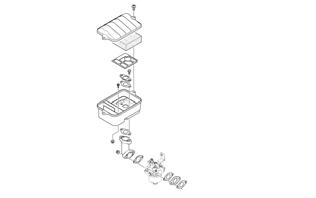
4.Spark plug cap resistance must be between 40006000 ohms. MAGNETO 1.Disconnect the two white wires from the main harness. 2.Set the meter selector to the OHMS position; then connect the red and black tester leads to each of the two white wires. 3.The meter must show less than 1 ohm. EXTERNAL COIL Primary 1.Disconnect the single black/white wire lead of the coil from the main harness. 2.Set the meter selector to the OHMS position; then connect the red tester lead to the black/white wire and the black tester lead to the metal post of the coil. 3.Resistance must be within 11.25-11.75k ohms. Secondary 1.Remove the spark plug end cap from the high tension lead of the coil. 2.Set the meter selector to the OHMS position; then connect the red lead of the tester to the high tension lead to the coil and the black tester lead to ground. 3.Resistance must be within 6000-7000 ohms. LIGHTING COIL 1. Disconnect the two yellow wires from the main wiring harness. 2.Set the selector to the OHMS position. 3.Connect the tester leads to the two yellow leads on the engine-side connectors. 4.Lighting coil resistance must be between 0.46-0.68 ohm.
Testing Handlebar Warmer Elements
NOTE: Resistance will vary due to temperature;
therefore, this test should be made at room temperature of 22° C (72° F).
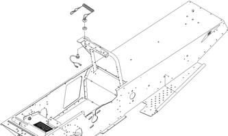
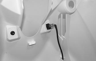
1.Open the hood; then disconnect the handlebar warmer two-wire connector. 2.Connect one ohmmeter lead to the green/white lead (A); then connect the other ohmmeter lead to the yellow lead (B).
ZR-114
3.The meter must read 14.4 ± 10% ohms. 4.Replace any element measuring less than or more than the specified amount. 5.Repeat test for the other element; then connect the leads. Close and latch the hood.

Testing Tether
NOTE: Resistance will vary due to temperature;
therefore, this test should be made at room temperature of 22° C (72° F).
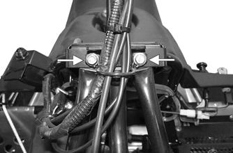
1.Disconnect the two-wire connector from the tether switch.
Testing Handlebar Warmer Switch
1.Open the hood; then disconnect the main harness wires from the switch. 2.With the handwarmer toggle in the OFF position, connect one ohmmeter lead to pin and the other ohmmeter lead to pin. The meter must read 1 ohm or less resistance.
3.With the handwarmer toggle in the ON position, connect one ohmmeter lead to pin and the other ohmmeter lead to pin. The meter must read 1 ohm or less resistance. 4.Connect the green/white wire to the bottom terminal and the brown wire to the top terminal on the switch.
ZR-115
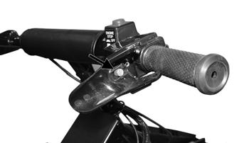
SNO-996
2.Connect one ohmmeter lead to one pin; then connect the other ohmmeter lead to the other pin. 3.With the reverse button pressed in, the meter must read less than 1 ohm of resistance. With the reverse button released, the meter must read OL (infinite resistance). NOTE: If the meter does not read as specified in
either test, the switch is defective and must be replaced.