12 minute read
Drive System

Drive Chain and Sprockets
REMOVING 1.Remove the self-tapping screws securing the front clutch shield and rear sprocket cover; then remove from the engine compartment. Note the position of the hood cable.
NOTE: It will be necessary to reinstall the hood
cable once the guard is removed.
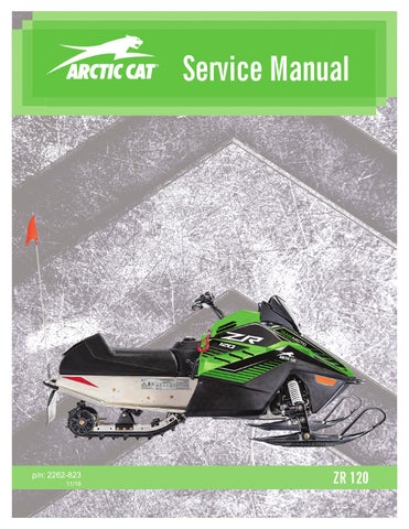
2.Remove the muffler hold-down spring from the muffler and support bracket; then remove the two nuts securing the muffler to the engine.
IO111A
3.Press down on the muffler and pull it to the side until the muffler flange clears the engine exhaust studs; then remove the muffler from the engine compartment. Account for the exhaust gasket. 4.Compress and hold the brake lever; then remove the cap screw and washer securing the chain sprocket to the driveshaft. Release the lever.

IO118A
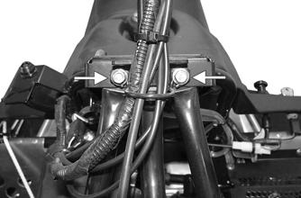
5.Remove the retaining ring (A) securing the brake band. Account for a washer; then loosen the rear brake cable adjustment jam nut (B) and slide the cable out of the brake bracket. Set the band assembly aside.
IO112A
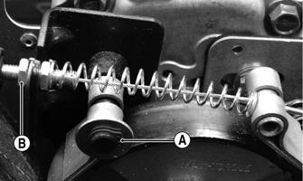
6.Secure the centrifugal clutch with a pair of channellock pliers at the outer clutch collar; then remove the cap screw securing the clutch. Account for a lock washer and a flat washer.
A020

IO113
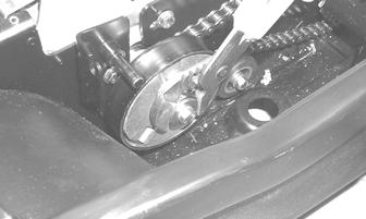
7.Slide the chain sprocket and clutch (with the drive chain) off the respective shafts and remove from the engine compartment. Account for the rear driveshaft key. CLEANING AND INSPECTING 1.Thoroughly wash all metallic components in partscleaning solvent. Dry using compressed air. 2.Wash all non-metallic components with soap and water. 3.Inspect the sprocket driveshaft for damage or for stripped threads. 4.Inspect the keyways in the driveshaft, chain sprocket, and clutch for wear or damage. 5.Inspect the chain and chain sprocket for wear or damage. 6.Inspect the driveshaft sprockets for wear or damage.
INSTALLING 1.Slide the chain sprocket/clutch/drive chain assembly into position; then install the key into the new sprocket.

IO114A
2.Secure the clutch with a pair of channel-lock pliers at the outer clutch collar; then install the cap screw with lock washer and a flat washer. Tighten to 20 ft-lb.
A020
3.Slide the brake band over the clutch and secure the brake band with a washer and retaining ring (A); then with the brake cable installed in the bracket, tighten the rear brake cable adjustment jam nut (B) securely.
IO112A
4.Compress and hold the brake lever; then install the cap screw (coated with red Loctite #271) and washer securing the chain sprocket. Tighten the cap screw to 20 ft-lb; then release the lever. 5.Place the exhaust gasket into position on the engine exhaust studs. 6.Place the muffler into position in the engine compartment; then press down on the muffler and position the flange onto the engine exhaust studs. Secure with two nuts and the hold-down spring. 7.Place the front clutch shield and rear sprocket cover into position making sure the hood cable is properly positioned. Tighten the self-tapping screws securely.
Track and Driveshaft
NOTE: The skid frame must be removed for this
procedure (see Rear Suspension section).
REMOVING 1.Remove the self-tapping screws securing the rear sprocket cover; then remove the cover. 2.Compress and hold the brake lever; then remove the cap screw and washer securing the chain sprocket to the driveshaft. Release the lever.
IO118A
3.Slide the chain sprocket off the driveshaft and set aside. Account for the key.
IO114A
4.Remove the cap screws securing the upper idler wheel assembly to the tunnel; then remove the assembly from the tunnel.


IO115A
5.Remove the four lock nuts securing the drive sprocket bearings to the tunnel; then remove the four carriage bolts from the tunnel.

A021
6.Position the bearing flanges so they are directed toward the rear; then spread the tunnel slightly and slide the driveshaft assembly out of the tunnel.

A022
7.Remove the track from the tunnel. INSPECTING 1.Inspect the driveshaft for damage and for stripped threads. 2.Inspect the bearings for roughness or damage. 3.Inspect the track for cuts, gouges, or wear. 4.Inspect the keyways in the driveshaft and in the chain sprocket for wear or damage. 5.Inspect the chain and chain sprocket for damage or wear. 6.Inspect the track drive sprockets for wear or damage.
KEY 1.Drive Sprocket 2.Carriage Bolt 3.Bearing 4.Track Drive Assy 5.Hex Nut 6.Driveshaft 7.Key 8.Chain Sprocket 9.Chain 10.Cap Screw 11.Washer
SNO-990
1.Tip the snowmobile on its left side; then place the track into position in the tunnel.
CAUTION
A piece of cardboard should be used to protect the finish on the hood.
A022
2.Slide the driveshaft assembly into position in the tunnel; then secure the drive sprocket bearings with carriage bolts and lock nuts. Tighten lock nuts to 15 ftlb.
A021
3.Place the upper idler wheel assembly into position in the tunnel; then secure with cap screws. Tighten securely. 4.Install the skid frame (see Rear Suspension section). 5.Place the snowmobile in the upright position. 6.Place the key on the driveshaft; then slide the chain sprocket w/chain onto the driveshaft. Secure with a cap screw (coated with red Loctite #271) and washer.
Tighten to 20 ft-lb.
7.Inspect the chain for proper engagement with the clutch sprocket and the chain sprocket. 8.Inspect that the chain tensioner assembly is in place and functioning properly. 9.Install the rear sprocket cover and secure with the self-tapping screws. Tighten securely. NOTE: At this point, proceed to TRACK TENSION
sub-section.
TRACK TENSION NOTE: Track tension and track alignment are
interrelated; therefore, always check both, even if only one adjustment seems necessary.
Track tension is directly related to the overall performance of the snowmobile. If the track is too loose, it may slap against the tunnel causing wear, or it may ratchet on the track drive sprockets. Arctic Cat recommends that the track tension be checked once a month and adjusted accordingly.
! WARNING
Track tension must be properly maintained. Personal injury could result if a track is allowed to become excessively loose.
Checking
! WARNING
DO NOT attempt to check or adjust track tension with engine running. Turn ignition key to the OFF position. Personal injury could result from contact with a rotating track.
1.Remove excess ice and snow buildup from the track, track drive sprockets, and the inside of the skid frame. 2.Place the rear of the snowmobile up on a safety stand high enough so the track is free of the floor. 3.Without exerting any pressure on the track, measure the distance between the bottom of the wear strip and the inside surface of the track. The measurement must be within specifications. If the measurement is not within 1/4-3/8 in., an adjustment is necessary.

0744-947
NOTE: To ensure proper track tension adjustment,
perform all adjustments on both sides of the snowmobile.
3.If the deflection (distance between the bottom of the wear strip and the inside of the track) exceeds specifications, tighten the adjusting bolts to take up excessive slack in the track. 4.If the distance between the bottom of the wear strip and the inside surface of the track is less than specified, loosen the adjusting bolts to increase the slack in the track. 5.Check track alignment (see TRACK ALIGNMENT sub-section). 6.When proper track tension is obtained, tighten the adjusting bolt jam nuts against the axle housings. 7.Tighten the idler wheel cap screws securely. NOTE: Since track tension and track alignment are
interrelated, always check both even if only one adjustment seems necessary.
TRACK ALIGNMENT Proper track alignment is obtained when the rear idler wheels are equal distance from the inner track drive lugs. Excessive wear to the idler wheels, drive lugs, and track will occur if the track is improperly aligned. Arctic Cat recommends that the track alignment be checked once a week or whenever the track tension is adjusted.
! WARNING
If jam nuts are not tightened properly, the adjusting bolts could loosen causing the track to become extremely loose and, under some operating conditions, allow the idler wheels to climb over the track lugs forcing the track against the tunnel causing the track to “lock.” If a track “locks” during operation, severe personal injury could result.
0744-945
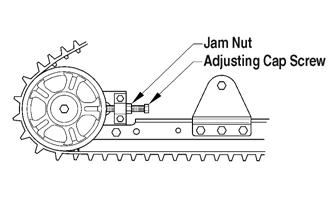
Adjusting 1.Loosen the idler wheel cap screws. 2.Loosen the rear idler wheel adjusting bolt jam nuts.
Make sure the ignition key is in the OFF position and the track is not rotating before checking or adjusting track alignment. Personal injury could result if contact is made with a rotating track.
1.Position the tips of the skis against a wall; then using a shielded safety stand, raise the rear of the snowmobile off the floor making sure the track is free to rotate.
2.Start the engine and accelerate slightly. Use only enough throttle to turn the track several revolutions.
SHUT ENGINE OFF.
! WARNING
The tips of the skis must be positioned against a wall or similar object for safety.
NOTE: Allow the track to coast to a stop. DO NOT
apply the brake because it could produce an inaccurate alignment condition.

3.When the track stops rotating, check the relationship of the idler wheels and the edge of the track. If the distance from the rear idler wheels to the edge of the track is the same on both sides, no adjustment is necessary. 4.If the distances from the idler wheels to the edge of the track are not the same on both sides, an adjustment is necessary. Adjusting Track Alignment 1.On the side of the track which has the edge of the track furthest to outside of the rear idler wheel, loosen the idler wheel cap screw and the adjusting bolt jam nut; then rotate the adjusting bolt clockwise 1 to 1 1/2 turns.

SNO-949
2.Check track alignment and continue adjustment until proper alignment is obtained. NOTE: Make sure correct track tension is main-
tained after adjusting track alignment (see Track Tension section).
3.After proper track alignment is obtained, tighten both the adjusting bolt jam nut and the idler wheel cap screw securely.
! WARNING
If a jam nut is not tightened properly, the adjusting bolt could loosen causing the track to become dangerously loose.
Brake System
REMOVING AND INSPECTING
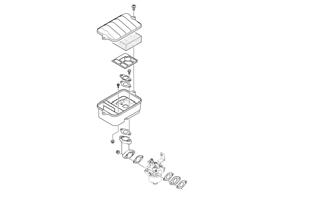
KEY 1.Lock Nut 2.Bushing 3.Rivet 4.Chain Tensioner 5.Spring 6.Tab 7.Roller 8.Washer 9.Cap Screw 10.Bracket 11.Cap Screw 12.Spacer 13.Clutch 14.Brake Band 15.Retainer Pin 16.Washer 17.Retaining Ring 18.Spacer 19.Washer 20.Lock Washer
742-425B
1.Remove the front clutch shield and hood cable.
NOTE: It will be necessary to reinstall the hood
cable once the shield is removed.
2.Loosen the Allen-head retainer pin (A) securing the brake cable to the brake band; then remove the retaining ring (B) securing the brake band to the mounting bracket.

IO116A
3.Loosen the rear jam nut securing the brake cable to the brake bracket; then remove the brake cable from the bracket and brake band. Account for a spring. 4.Remove the brake band from the engine compartment.
ZR-106
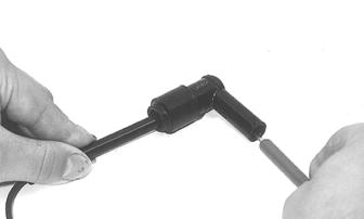
6.Disconnect the brake cable from the lever; then slide the brake cable out of the lever.


ZR-107
7.Remove the handlebar pad and cut the cable tie securing the brake cable to the steering post. NOTE: Note the location of the cable tie for assem-
bly.
8.Inspect the brake band for cracks and/or wear. NOTE: The brake band pad material thickness
must be at least 1/16” or replacement is necessary.
9.Inspect the brake cable for damage or fraying. INSTALLING 1.Route the cable through the slot in the brake housing and insert the cable end into the housing. 2.Seat the cable drum into the brake lever recess; then secure the brake lever with a pin and C-clip.

ZR-106
3.Place the brake band into position on the bracket and secure with a washer and retaining ring.

IO117A
4.Slide the spring onto the brake cable; then insert the cable end into the brake band. Tighten securely.
A004
5.Secure the brake cable to the bracket with the jam nuts.

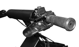
6.Secure the brake cable to the steering post with a cable tie; then install the handlebar pad. 7.Install the hood cable and the front clutch shield. CHECKING BRAKE LEVER TRAVEL 1.Compress the brake lever fully. 2.Check the distance between the brake lever and the lever stop. The distance must be within a range of 1/4-1/2”.
0725-565
3.If travel distance is not as specified, adjust the brake.

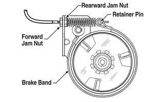
735-457A
1.Remove the clutch shield. 2.Loosen the rearward jam nut on the brake cable; then tighten the forward jam nut to set up the brake. 3.Check the brake lever travel distance periodically while tightening the forward jam nut. When the distance is within the specified range of 1/4-1/2”, tighten the rearward jam nut to secure the adjustment. 4.Install the clutch shield.
Troubleshooting Track
Problem: Track Edge Frayed — Drive Lugs Worn Condition Remedy
1. Track alignment adjusted incorrectly 1.Align — replace track
Problem: Track Worn Adjacent to Outer Drive Lugs Condition Remedy
1. Track tension adjusted incorrectly 1.Adjust track tension 2. Rear idler wheels dirty — damaged 2.Clean — replace idler wheels
Problem: Track Ratchets — Slaps Tunnel Condition Remedy
1. Track tension adjusted incorrectly (too loose) 1.Adjust track tension (tighten) 2. Drive sprockets misaligned — damaged 2.Align — replace sprockets
Problem: Wear-Strip Wear Excessive Condition Remedy
1. Slide rail bent — broken — damaged 1.Repair — replace slide rail 2. Track alignment adjusted incorrectly 2.Adjust track alignment