32 minute read
Engine

This engine section has been organized into sub-sections showing a progression for the complete servicing of the Arctic Cat 120 cc engine. For consistency purposes, this section shows a complete and thorough progression; however, for efficiency it may be preferable to remove and disassemble only those components needing to be addressed and to service only those components. Also, some components may vary. The technician should use discretion and sound judgment.
Removing
NOTE: The drive chain must be removed in order
to remove the engine (see Drive Chain and Sprockets section).
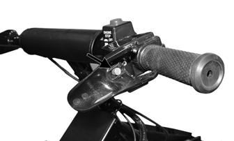
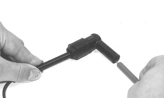
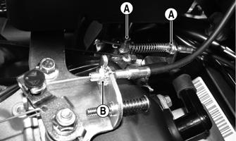
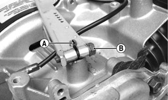
1.Loosen the pinch screw and jam nuts (A) securing the choke cable to the carburetor; then loosen the throttle cable jam nuts (B) and remove the cable from the mounting bracket. Secure the cables out of the way.
IO057A
2.Turn the gas tank shut-off valve to the CLOSED position; then disconnect the fuel hose from the carburetor.
3.Remove the two cap screws securing the steering post to the steering post support. Account for two bearing halves, two lock nuts, and a bearing retainer.
! WARNING
Whenever any maintenance or inspection is made on a fuel system when there may be fuel leakage, there should be no welding, smoking, open flames, etc., in the area.
ZR-111
4.Remove the two lock nuts and cap screws securing the tie rods to the steering post; then remove the tie rods from the steering post. Place the steering post out of the way on the right-hand side of the engine compartment.
ZR-112
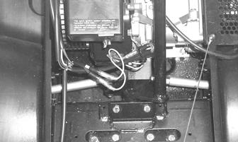
5.Disconnect the coil and two magneto wires at the front of the engine. Route them out of the way.
A047
6.Pull the recoil starter rope out for enough to tie a slip-knot in the starter rope below the console and allow the rope to slowly retract against the recoil starter. 7.Remove the knot at the handle and remove the handle; then thread the rope through the bushing in the console. 8.At this point, scribe a line at the front of the engine and measure the distance between the crankshaft and the driveshaft. Record the measurement for installing purposes.

A048
9.Lay the snowmobile on its left side. NOTE: Always tip the snowmobile onto the left side
to avoid oil from draining into the air intake.
NOTE: A piece of cardboard should be used to pro-
tect the finish.
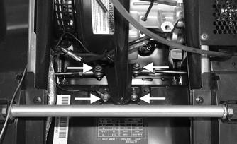
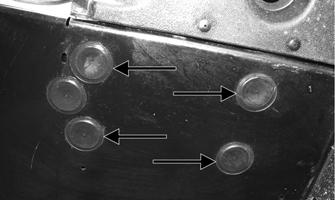
10.Using a flat-blade screwdriver, remove the four belly pan plugs covering the engine mounting cap screws; then remove the cap screws and lock nuts.
IO061A
NOTE: The front center plug is to access the oil
drain plug.
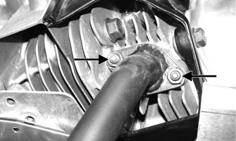
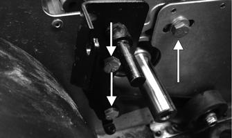
11.Place the snowmobile in the upright position; then on the left-hand side of the engine, remove the three cap screws securing the engine and brake bracket to the front end.
IO062A
12.Remove the engine from the engine compartment.
Disassembling
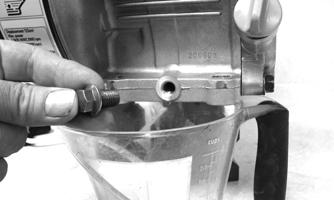
1.Remove the oil drain plug and drain the oil; then install the oil plug and tighten securely.
IO063
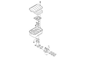
2.Remove the cover from the air cleaner case; then disconnect the breather hose and remove the filter and retaining plate. NOTE: The retaining plate is directional.

IO056A
3.Remove the two cap screws securing the air cleaner case to the intake tube; then remove the cap screw and lock nut securing the case to the throttle cable bracket, remove the air cleaner case and account for the intake tube gasket.

IO064A
4.Remove the two springs from the governor arm, throttle cable bracket, and retaining bracket.

IO065A
NOTE: For assembling purposes, note the location
of the governor arm spring before removing.
5.Remove the throttle cable and retaining brackets from the engine.

IO066A
6.Loosen the governor arm cap screw and remove the arm; then disconnect the rod and spring from the carburetor.

IO067A
7.Slide the intake tube and carburetor off the mounting studs. Account for three gaskets and an insulator block.

IO068
NOTE: If the cylinder head will be replaced, the
carburetor studs may be removed by tightening the two nuts against each other; then using a wrench on the inside nut, remove the stud.
8.Remove the recoil starter/fan housing assembly. 9.Remove the spark plug wire from the spark plug and remove the spark plug; then remove the cap screws securing the ignition coil to the crankcase housing and remove the coil.
IO069A
10.Remove the cylinder head cover; then remove the air shroud.

IO070A
11.Remove the air breather body from the cylinder head cover. Account for a gasket.

IO071
12.Remove the lock nuts and rocker arm pivots securing the rocker arms to the cylinder head. 13.Remove the push rods; then remove the push rod guide plate.

IO072A
14.Remove the cap screws securing the head to the cylinder; then remove the head and account for a gasket and the location of the two dowel pins.


IO073
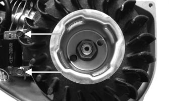
15.Remove the nut securing the flywheel to the crankshaft and starter pulley.
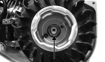
IO069B
16.Using a flywheel puller, remove the flywheel.
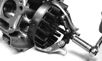
IO074
17.Remove the cap screws securing the stator to the crankcase; then route the stator harness out through the slot in the crankcase and remove the stator.
IO075A
18.Remove the cap screws securing the crankcase side cover to the crankcase. Account for dowel pins, gasket, and a crankshaft shim.

IO077
19.With the piston at TDC, scribe an alignment mark on the gear of the camshaft directly in-line with the alignment dot on the crankshaft gear.

IO078A
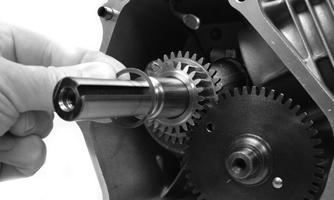
20.Remove the camshaft; then remove the tappets. Identify the tappets for proper installation.
IO079A
21.Rotate the crankshaft until the connecting rod cap screws are accessible. 22.Note the relation of the connecting rod journal to the crankshaft and mark the connecting rod and end cap for reference during installation; then remove the cap screws and connecting rod end cap.
IO081A
23.Carefully work the connecting rod/piston up and out of the cylinder; then remove the crankshaft. NOTE: For assembling purposes, note the arrow
mark on the dome of the piston is directed to the push rod opening of the cylinder.
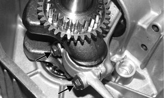
24.Remove the hairpin clip from the governor control shaft; then remove the shaft and account for the washer.
IO082A
25.Inspect the crankshaft and governor control shaft oil seals for cracks or deterioration; then inspect the crankshaft bearings for roughness or discoloration and replace if necessary. NOTE: If the seals or bearings of the crankshaft
need to be replaced, see Crankshaft Bearings in Servicing Components.
Servicing Components
Thoroughly clean all non-electrical components in partscleaning solvent; then remove any carbon buildup from the cylinder head, piston dome, valves, and valve seats. Visually inspect all engine components for wear or damage.
CYLINDER HEAD/VALVE ASSEMBLY NOTE: Remove the valves by pressing down on the
spring retainer and removing the valve keeper. Account for valve springs, spring retainers, and valve keepers. Keep all valves and related components as a set.
When servicing valves and cylinder head assembly, inspect valve seats, head warpage, valve stems, valve faces, and valve stem ends for pits, burn marks, or other signs of abnormal wear. Never reuse the intake valve seal. Always replace the seal. NOTE: Discard any valve that fails the listed inspec-
tions. Do not grind the valves. If a valve or cylinder head is damaged, it must be replaced.
Measuring Cylinder Head Distortion 1.Using a non-metallic carbon removal tool, remove any carbon buildup from the combustion chamber being careful not to nick, scrape, or damage the combustion chamber or the sealing surfaces. 2.Inspect the spark-plug hole for any damaged threads.
Repair damaged threads using a heli-coil insert. 3.Inspect the cylinder head for flatness using a straightedge and a feeler gauge. Acceptable distortion must not exceed 0.004".

IO087
Measuring Valve Stem Runout 1.Support each valve stem end with V Blocks; then check the valve stem runout using a dial indicator.
ATV-1082
2.Maximum runout must not exceed 0.0004" for both valves.
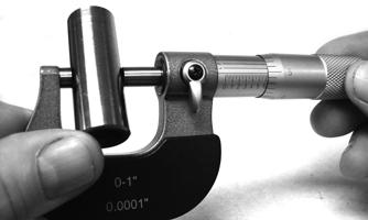
Measuring Valve Face Width 1.Using a micrometer, measure the width of the valve face.
ATV-1004
2.Acceptable valve face width must be at least 0.030". Measuring Valve Face Runout 1.Mount a dial indicator on a surface plate; then place the valve stem on a set of V blocks. 2.Position the dial indicator contact point on the outside edge of the valve face; then zero the indicator.
ATV1082A
3.Rotate the valve in the V blocks. 4.Maximum runout must not exceed 0.0012”. Measuring Valve Guide/Valve Stem Clearance 1.Using a micrometer and small bore gauge, take diameter readings on the valve stems and inside the guides. 2.The stem clearance inside the guide must be within 0.0016-0.0020” for the intake and 0.0020-0.0030” for the exhaust.
NOTE: Be sure to take readings at more than one
place along the length of each stem and guide.
Lapping Valves NOTE: Ensure that all carbon has been removed
from the valves.
1.Using a valve lapper, produce a contact pattern on each valve face by applying a uniform coat of valve lapping compound to the valve seat and by rotating and tapping the valve head.
GEN-0023
GEN-0024
NOTE: Do not grind the valves. If a valve is dam-
aged, it must be replaced.
3.Lubricate each valve stem with lightweight oil; then apply a small amount of valve lapping compound to the entire seating face of each valve. 4.Attach the suction cup of a valve lapping tool to the head of the valve. 5.Rotate the valve until the valve and seat are evenly polished. 6.Clean all compound residue from the valve and seat. Valve Springs 1.When the valve springs are weak, the valve and valve seat fail to form a good seal, thus allowing gas to leak past the valve seat causing a loss of power.
Whether or not a valve spring is weak can be determined by its free length. NOTE: With the crankshaft at top dead center on
the compression stroke, install the valve springs and spring retainers; then compress the valve springs and install the valve keepers.
CAM LOBE WEAR Worn cam lobes result in reduced power output. The limit of cam lobe wear is specified for both intake and exhaust lobes in terms of cam height to be measured with a micrometer. Replace the camshaft if not within 1.0481.052”.


GEN0028B

IO088
Measuring Camshaft End Running Surfaces 1.Using an outside micrometer, measure the running surfaces of each end of the camshaft. The measurement should be at least 0.592”.

IO089
2.Inspect the camshaft bosses of the crankcase and crankcase cover for cracks, discoloration, and wear.
PISTON ASSEMBLY NOTE: Oversized pistons are available allowing the
cylinder to be bored oversized.
NOTE: Whenever a piston, rings, or pins are out of
tolerance, they must be replaced.
Cleaning/Inspecting Piston 1.Using a non-metallic carbon removal tool, remove any carbon buildup from the dome of the piston. 2.Inspect the piston for cracks in the piston pin, dome, and skirt areas. 3.Inspect the piston for seizure marks or scuffing. NOTE: If seizure marks or scuffing is detected, the
piston must be replaced.
4.Inspect the perimeter of each piston for signs of excessive “blowby.” Excessive “blowby” indicates worn piston rings or an out-of-round cylinder. Removing Piston Rings 1.Starting with the top ring, slide one end of the ring out of the ring-groove. 2.Remove each ring by working it toward the dome of the piston while rotating it out of the groove. NOTE: Note the location of each ring for proper
installation. When installing new rings, install as a complete set only.
Cleaning/Inspecting Piston Rings NOTE: Make a ring-groove cleaning tool by taking
an old piston ring and snapping it into two pieces; then grind the end of the old ring to a 45° angle and to a sharp edge.
Using a ring-groove cleaning tool, clean carbon from the ring-grooves. Be sure to position the ring with its tapered side up.
CAUTION
Improper cleaning of the ring-grooves by the use of the wrong type of ring-groove cleaner will result in severe damage to the piston.
Measuring Piston-Ring End Gap (Installed) 1.Place each piston ring in the wear portion of the cylinder. Use the piston to position each ring squarely in the cylinder. NOTE: When measuring a piston ring, it should be
placed into the area of the cylinder where wear is least (the area is about 0.12" from the upper or lower edge of the cylinder).
2.Using a feeler gauge, measure each piston-ring end gap. Acceptable ring end gap must be within 0.0080.016” (1st and 2nd rings) or within 0.0079-0.0157” (oil ring).

IO083

IO090
Piston Ring/Groove Clearance 1.Using a thickness gauge, measure the side clearances of the 1st and 2nd rings. 2.If the measurements are not within 0.0016- 0.0030” (1st ring) or 0.0008-0.0024” (2nd ring), replace both piston and piston rings. Measuring Piston Skirt/Cylinder Clearance 1.Measure the cylinder front to back in six places using a cylinder bore gauge. The amount of wear is the difference between the largest and smallest readings. If the determined wear exceeds the limit indicated, bore to the next oversize by using a boring machine or replace the cylinder.
GEN-0032
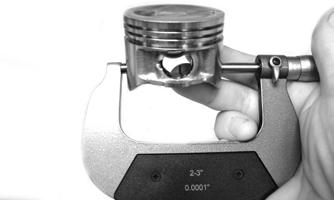
2.Measure the corresponding piston diameter at a point 10 mm above the piston skirt at a right angle to the piston-pin bore. Piston diameter must be at least 2.205”.
IO085
3.Piston skirt to cylinder clearance must be within 0.0006-0.0016”. 4.If the piston/cylinder clearance exceeds the limit, bore the cylinder and use an oversized piston or replace both cylinder and piston. Installing Piston Rings 1.Place the oil ring expander into the bottom groove of the piston allowing the ends to contact each other.
2.Place one end of the thin oil ring between the top of the oil ring expander and the ring groove; then wind the ring around the piston until the ring is properly seated into the ringland of the piston. Repeat this procedure for the lower thin oil ring. 3.Position the thin oil ring gaps 90° from the gap of the oil ring expander and 180° from each other. 4.Install the middle and top compression ring with the
I.D. mark directed toward the dome of the piston. NOTE: The top compression ring can be identified
by the chrome (silver) face of the ring.
Measuring Piston Pin Diameter 1.Measure the piston pin diameter at each end and in the center. If measurement is less than minimum specifications, the piston pin must be replaced. 2.Piston pin diameter must be within 0.6297-0.6299”.
CAUTION
Never allow the ends of the oil ring expanders to overlap. This allows a loss of oil control and incorrect tension of the ring.
CAUTION
Incorrect installation of the piston rings will result in engine damage.
IO086
Measuring Piston Pin Bore Diameter 1.Insert an inside dial indicator into the piston-pin bore. Take two measurements to ensure accuracy. 2.Piston pin bore must not exceed 0.633".

ATV-1069
CYLINDER/CYLINDER HEAD NOTE: If the cylinder/cylinder head assembly can-
not be trued, they must be replaced.
Cleaning/Inspecting Cylinder Head 1.Using a non-metallic carbon removal tool, remove any carbon buildup from the combustion chamber being careful not to nick, scrape, or damage the combustion chamber or the sealing surface. 2.Inspect the spark plug hole for any damaged threads.
Repair damaged threads using a “heli-coil” insert. 3.Place the cylinder head on the Surface Plate covered with #400 grit wet-or-dry sandpaper. Using light pressure, move the cylinder head in a figure-eight motion. Inspect the sealing surface for any indication of high spots. A high spot can be noted by a bright metallic finish. Correct any high spots before assembly by continuing to move the cylinder head in a figure-eight motion until a uniform bright metallic finish is attained.
CAUTION
Water or parts-cleaning solvent must be used in conjunction with the wet-or-dry sandpaper or damage to the sealing surface may result.
Cleaning/Inspecting/Measuring Cylinder Distortion 1.Wash the cylinder in parts-cleaning solvent.
2.Check the gasket surface of the cylinder for distortion with a straightedge and thickness gauge taking a clearance reading at several places. If the largest reading at any position of the straightedge exceeds the limit, replace the cylinder. 3.Maximum cylinder distortion must not exceed 0.004".
IO087
4.Inspect the cylinder for pitting, scoring, scuffing, warpage, and corrosion. If marks are found, repair the surface using the Ball Hone (see Honing Cylinder sub-section). 5.Place the cylinder on the surface plate covered with #400 grit wet-or-dry sandpaper. Using light pressure, move the cylinder in a figure-eight motion. Inspect the sealing surface for any indication of high spots.
A high spot can be noted by a bright metallic finish.
Correct any high spots before assembly by continuing to move the cylinder in a figure-eight motion until a uniform bright metallic finish is attained.
CAUTION
Water or parts-cleaning solvent must be used in conjunction with the wet-or-dry sandpaper or damage to the sealing surface may result.
Honing Cylinder 1.Wash the cylinder in parts-cleaning solvent. 2.Inspect the cylinder for pitting, scoring, scuffing, and corrosion. If marks are found, repair the surface using the Ball Hone. NOTE: To produce the proper 45° crosshatch pat-
tern, maintain a low drill RPM. If honing oil is not available, use a lightweight, petroleum-based oil. Thoroughly clean the cylinder after honing using detergent soap and hot water and dry with compressed air; then immediately apply oil to the cylinder bore. If the bore is severely damaged or gouged, the cylinder must be replaced.
3.If the cylinder bore measurement exceeds the limit, hone the cylinder and install an oversized piston or replace the cylinder. MEASURING CONNECTING ROD SMALL END BORE INSIDE DIAMETER 1.Using a small bore gauge, measure the connecting rod small end bore inside diameter. 2.Measurement must be within 0.6301-0.6307”.
GEN-0034
3.If the difference between the connecting rod small end bore inside diameter and the piston pin outside diameter exceeds the limit, replace both connecting rod and piston pin. The measurements must be within 0.0001-0.0002” of each other.
GEN-0035
CRANKSHAFT RUNOUT 1.Support the crankshaft using a set of V blocks; use a dial indicator to read crankshaft runout.
NOTE: The contact point of the dial indicator
should be on the seal area of the crankshaft.
2.Total indicator reading must not exceed 0.0008".
GEN-0031
3.If not within specification, either straighten the crankshaft or replace it. MEASURING CONNECTING ROD BIG END SIDE CLEARANCE 1.Check the connecting rod side clearance by using a thickness gauge. If the clearance exceeds the limit, replace the connecting rod or crankshaft.
GEN-0036
MEASURING CRANK PIN/ CONNECTING ROD CLEARANCE 1.Measure the crank pin diameter. Measurement must be at least 1.102".
GEN-0039

CRANKSHAFT BEARINGS
GEN-0037
2.Measure the connecting rod big end bore inside diameter. Measurement must be within 1.10231.1029”.
GEN-0038
3.Measure the crank pin/connecting rod clearance.
Measurement must be within 0.0002-0.0008”.
0744-992
Removing 1.Using a flat-blade screwdriver, carefully work the oil seal from side-to-side out of the crankcase and cover. 2.Using a suitable press and with the crankcase or crankcase cover secured into position, carefully heat the case; then press the bearings out of the case.
CAUTION
Never reuse the crankshaft bearings. If the bearings have been pressed out of the crankcase or crankcase cover, they must be discarded.
NOTE: Thoroughly clean the bearing areas of the
crankcase and crankcase cover and inspect for any nicks or imperfections of the bearing bosses of the case.
Installing 1.Secure the crankcase and press the new bearing into the boss of the crankcase and crankcase cover.
2.With the bearings installed and using a suitable seal driver, install the oil seals with the spring side of the seal facing the bearing; then coat the wear surfaces of the seals with a film of grease. CARBURETOR INSULATOR PLATE 1.Inspect for cracks, scoring, pitting, imperfections, or warping. CAUTION
When installing the new bearings, always press against the outside race of the bearing.
2.Inspect the sealing surfaces for trueness by placing each on the surface plate covered with #400 grit wetor-dry sandpaper. Using light pressure, move both sides in a figure-eight motion. Inspect the sealing surfaces for any indication of high spots or warping.
Correct highs spots by continuing to move each side in a figure-eight motion. Warped components must be replaced.
CAUTION
Water or parts-cleaning solvent must be used in conjunction with the wet-or-dry sandpaper or damage to the sealing surfaces may result.
Assembling
NOTE: The use of new gaskets and seals is recom-
mended when assembling the engine.
NOTE: Prior to assembling the engine, use parts
cleaning solvent and compressed air and thoroughly clean the threaded holes of the crankcase and cylinder and head to properly tighten.
! WARNING
Always wear safety glasses when drying components with compressed air.
NOTE: When the use of a lubrication is indicated,
use clean engine oil.
1.Lubricate the piston pin, connecting rod, and piston pin bore with engine oil; then install the piston to the connecting rod and secure the piston pin with the circlips directed either up or down.

IO091A
NOTE: Coat the cylinder wall, connecting rod bear-
ing surface, and the crankshaft with engine oil.
2.Install the crankshaft into the crankcase; then with the piston rings properly oriented (end gap 120° apart), compress the piston rings and install the piston and connecting rod assembly taking care not to damage the crankshaft and connecting rod.
CAUTION
The arrow of the piston must be directed toward the push rod opening of the cylinder.
0745-001
3.Note the marks on the connecting rod and end cap made during disassembly.
IO081A
NOTE: When installing the connecting rod to the
crankshaft, rotate the crankshaft so the rod journal is in the six o’clock position to allow access for installing the rod end cap.
4.With the connecting rod, end cap, and crankshaft journal lubricated with engine oil, install the connecting rod and rod end cap to the crankshaft and secure with the cap screws. Tighten evenly to 106 in.-lb.
IO080A
5.Apply lightweight oil to the tappets; then install the tappets to the proper guides as noted during disassembly.
IO079A
6.Apply oil to the camshaft lobes and running surfaces on each end of the shaft; then with the crankshaft/ piston rotated to TDC and the timing marks of the crankshaft gear in-line with the camshaft gear, install the camshaft.
IO078A
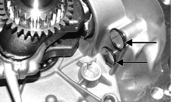
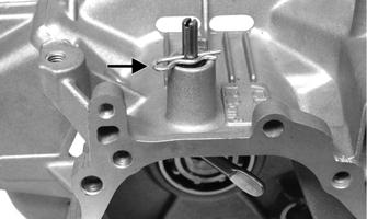
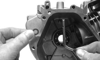
7.Install the washer onto the governor control shaft and slide the shaft up into position from inside the crankcase far enough to install the hairpin clip.
IO101
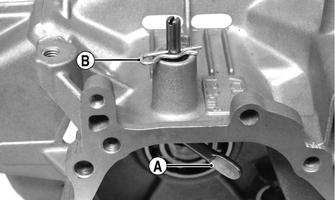
NOTE: When installing the governor control shaft,
position the shaft so the flat end (A) of the shaft is directed to the cylinder (3 o’clock position) and the hairpin clip (B) is in contact with the crankcase. This limits the inward movement of the control shaft.
IO082B

IO093A
8.Install the shim washer to the crankshaft and place the dowel pins and a gasket into position.
IO077
9.Secure the crankcase side cover to the crankcase with the cap screws. Tighten to 16 ft-lb using the following pattern.
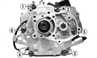
IO094A
10.Install the dowel pins and a new gasket; then secure the head to the cylinder with the cap screws. Tighten to 15 ft-lb using a crisscross pattern.
IO073
11.Apply lightweight oil to the ends of the push rods; then install the rods. 12.Loosely secure the rocker arms to the cylinder head with the pivots and lock nuts; then rotate the crankshaft until the piston is at the top of the compression stroke.

IO107
13.Set the valve clearance to the recommended setting with a feeler gauge, and while holding the adjustment nut, tighten the rocker arm lock nuts to 88 in.lb. Verify valve clearance is 0.004”. 14.Install the air shroud to the cylinder head and secure the shroud with cap screw. Tighten to 96 in.-lb.

IO098A
15.Place the air breather body assembly with gasket onto the cylinder head cover; then install the valve cover with gasket. Tighten to 96 in.-lb using a crisscross pattern.
IO070A
16.Install the ignition coil to the mounting location of the crankcase with the cap screws (coated with blue
Loctite #243); then adjust the ignition coil to the farthest position from the flywheel and tighten the cap screws until snug.

IO096A
NOTE: Adjust spark plug gap to specification; then
install and tighten the plug to 15 ft-lb.
17.Connect the high tension lead to the spark plug and secure with the two wire forms. 18.Install the stator with the four cap screws (coated with blue Loctite #243) and in a crisscross pattern, tighten to 96 in.-lb.

IO097A
NOTE: Route the stator harness through the slot in
the crankcase above the flywheel.
19.With the flywheel key in the crankshaft, install the flywheel and starter pulley; then secure with the nut.
Tighten to 48 ft-lb.
IO069B
NOTE: Before installing the flywheel, make sure the
taper of the crankshaft and flywheel are clean.
20.Rotate the flywheel until the magnet of the flywheel is under the legs of the ignition coil; then insert a flat 0.020" feeler gauge between the lower leg of the coil and the flywheel.

IO099
21.Loosen the ignition coil mounting cap screws (from step 16) enough to allow the coil to draw against the feeler gauge. Tighten the cap screw enough to hold the position of the coil; then repeat the procedure for the other cap screw when an air gap of 0.015-0.023” is obtained. Tighten the coil cap screws to 120 in.-lb. 22.Install the recoil starter/fan housing assembly with cap screws and tighten to 96 in.-lb.

IO100A
23.Install the throttle cable mounting bracket and secure the bracket with two cap screws to the crankcase.
Tighten to 120 in.-lb.

IO105
24.Install the carburetor (with a gasket, insulator block, and a gasket) onto the mounting studs; then install the rod and spring (A) onto the carburetor.

IO102A
! WARNING
When performing service work on the fuel system, do not smoke or allow open flames near the snowmobile.
25.Install the rod and spring into the governor control arm and install the arm; then install the throttle lever spring into the proper hole of the control arm (as noted during disassembling) and the remaining spring to the retaining bracket.
IO065A
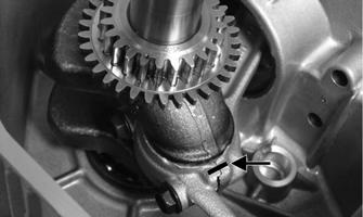
NOTE: When securing the governor control shaft
(A), turn it clockwise until it stops; then tighten the control arm cap screw (B) to 72 in.-lb.
IO067B
26.Install the gasket onto the mounting studs; then install the intake tube to the carburetor. Tighten to 96 in.-lb.
IO104
27.With a gasket in place on the intake tube, install the air cleaner case, and with gasket, insulator plate, and cap screws, secure the case to the intake tube and tighten the cap screws to 120 in.-lb. Install the cap screw and lock nut securing the case to the throttle cable bracket and tighten to 12 ft-lb.
IO064A
28.Install the retaining plate and fitting; then secure the air cleaner cover to the air cleaner case with the two screws. Tighten to 96 in.-lb. 29.Add 20.3 fl oz of the recommended engine oil to the engine.
Installing
1.Place the engine assembly into position in the engine compartment. 2.On the left-hand side of the engine, install the three cap screws (coated with blue Loctite #243) securing the engine and brake bracket to the front end. DO
NOT TIGHTEN AT THIS TIME.
IO062A
3.Align the engine with the scribed line made during removing; then measure the distance between the crankshaft and the driveshaft. Adjust the engine position as necessary. 4.Tighten the three left-hand side mounting cap screws (from step 2) to 20 ft-lb. 5.Lay the snowmobile on its side and install the four lower engine mounting cap screws with washers and lock nuts. Tighten to 20 ft-lb. 6.Install the four mounting cap screw plugs in the belly pan; then place the snowmobile in the upright position. 7.Thread the recoil starter rope through the bushing in the console and the handle; then tie a knot at the end of the rope and pull the handle up and onto the knot. 8.Untie the slip-knot at the starter case and allow it to slowly rewind into the case. 9.Install the tie rods on the steering post; then secure with lock nuts (threads coated with green Loctite #609) and washers. Tighten to 20 ft-lb. 10.Place the steering post in position in the lower steering post bearing and on the steering post support. 11.Place the upper steering post bearing into position on the steering post and support; then secure with the bearing retainer, cap screws, and lock nuts. 12.Position the throttle cable in the bracket; then connect the cable to the throttle lever. Tighten the adjustment jam nuts securely.

IO057B
NOTE: At this point, install the drive chain (see
Drive Chain and Sprockets section).
13.Install the choke cable into the bracket and carburetor butterfly arm. Adjust the cable and secure with the jam nuts and pinch screw.

IO106A
14.Install the breather tube into the air cleaner case. 15.Connect the engine wiring harness to the main wiring harness; then secure the wiring harnesses with a cable tie. 16.Connect the fuel hose to the carburetor; then turn the gas tank shut-off valve to the OPEN position.
Changing Oil
NOTE: The front of the snowmobile must be ele-
vated until the bottom of the front bumper is approximately 18.5" from the floor so the engine is in a level position when checking/changing the oil. Also, ensure the engine is “cooled down” to room temperature to allow the oil to drain into the sump.
0744-920
1.Remove the access plug; then place a drain pan beneath the engine. 2.Using a flat-blade screwdriver, release the hood latch; then release the two hold-down straps and open the hood. 3.Loosen the oil level stick; then remove the oil drain plug from the crankcase and allow the oil to drain. 4.Install the drain plug; then tighten to 12 ft-lb. 5.Remove the oil level stick; then pour 600 ml (20.3 fl oz) of recommended oil into the fill hole. 6.Install the oil level stick; then install the access plug. 7.Close the hood and secure with the straps and latch.
Recoil Starter
KEY
A.Cap Screw
B.Reel
C.Shoulder Screw
D.Drive Plate
E.Ratchet Arm Set
F.Friction Spring
G.Spiral Spring
0745-012
NOTE: The engine must be removed to access the
recoil starter (see Engine section).
REMOVING/DISASSEMBLING ! WARNING
Always wear safety glasses when servicing the recoil starter.
1.Remove the cap screws (A) securing the recoil starter to the engine cover. 2.Pull the rope out of the housing (noting the direction in which the rope is wound for assembling) and align with the notch in the roller; then release the spring pressure on the reel (B).
3.Remove the knot from the end of the rope; then remove the shoulder screw (C) securing the drive plate (D) to the reel and remove the plate. 4.Mark the ratchet arms (E) for assembling purposes; then remove the ratchets and account for the friction spring (F). NOTE: The ratchet arms must be installed in their
respective positions.
5.Slowly remove the reel. Account for the spiral spring (G).
INSPECTING 1.Inspect the spring retaining notch in the recoil housing and inspect the loop of the spring for wear or cracking. ! WARNING
Exercise extreme caution when removing as the spiral spring may disengage and cause severe injury.
NOTE: Note the orientation of the spring for assem-
bling purposes.
2.Inspect the flat areas of the reel for wear. ASSEMBLING/INSTALLING 1.Install the reel assembly with rope wound in the appropriate direction (noted during disassembling). ! WARNING
Exercise extreme caution when installing as the spiral spring may disengage and cause severe injury.
2.Install the ratchet arms; then install the drive plate and secure it with the shoulder screw. Tighten to 57 in.-lb. 3.Route the recoil rope through the rope guide of the recoil housing and through the recoil handle; then tie a knot in the rope. 4.Wind the rope counterclockwise 3-4 turns around the reel; then secure the recoil starter to the engine cover.
Tighten to 96 in.-lb.
Troubleshooting Engine
Problem: Engine Does Not Start (No Spark at Spark Plug) Condition Remedy
1. Ground connections dirty — loose 1.Check all ground connections — clean and tight 2. Wiring harness shorting — disconnected 2.Repair — replace — connect wiring harness 3. Emergency stop switch in DOWN position — malfunction- 3.Move switch to UP position — test/replace ignition key ing switch/emergency stop switch 4. Tether cord improperly secured to tether switch — malfunc- 4.Properly secure cord to the switch — test/replace switch tioning 5. Spark plug fouled — damaged 5.Clean — replace spark plug
Problem: Engine Does Not Start (No Fuel at Cylinder) Condition Remedy
1. Gas tank empty 1.Fill tank 2. Gasoline contaminated 2.Replace gasoline 3. Fuel hose broken — pinched 3.Replace — service hose 4. Gas-tank vent — hose obstructed 4.Remove obstruction — replace vent — hose 5. Shut-off valve obstructed — damaged 5.Remove obstruction — replace shut-off valve 6. Compression absent 6.Repair — replace damaged — worn engine components
Problem: Engine Does Not Start (Fuel Does Not Ignite) Condition Remedy
1. Valve clearance poor 1.Inspect valves 2. Spark absent 2.Check for spark — see No Spark at Spark Plug sub-section 3. Compression low 3.Service engine 4. Engine flooded 4.Clear engine (using a shielded safety stand, elevate the rear of the snowmobile and hold throttle full-open) 5. Gasoline contaminated 5.Clean tank and entire fuel system
Problem: Engine Does Not Idle Condition Remedy
1. Throttle stop screw turned out too far 1.Adjust throttle stop screw 2. Idle fuel adjuster screw out of adjustment 2.Adjust idle fuel adjuster screw 3. Air silencer obstructed 3.Clean air silencer 4. Drive clutch dirty 4.Clean drive clutch
Problem: Engine Loses Power Condition Remedy
1. Spark plug fouled 1.Replace spark plug 2. External coil faulty 2.Service — replace coil 3. Gas tank vent — hose obstructed 3.Service — replace vent hose 4. Compression low 4.Service engine 5. Muffler restricted 5.Inspect muffler
Problem: Engine Overheats Condition Remedy
1. Drive system adjusted incorrectly — worn — damaged 1.Troubleshoot — adjust drive system 2. Rings/grooves carboned 2.Clean — replace rings — pistons 3. Exhaust obstructed 3.Remove obstruction 4. Compression low — absent 4.Repair — replace damaged — worn engine components 5. Engine shroud obstructed 5.Clean shroud
Problem: Engine Backfires Condition Remedy
1. Spark plug fouled — damaged 1.Clean — replace spark plug
Problem: Engine Stops Suddenly Condition Remedy
1. Gas tank empty 1.Fill tank 2. Spark absent 2.See No Spark at Spark Plug sub-section 3. Fuel filter obstructed 3.Replace filter 4. Gas tank shut-off valve in OFF position 4.Turn on valve 5. Fuel hose obstructed — broken — pinched 5.Remove obstruction — repair — replace fuel hose 6. Ignition coil faulty 6.Replace ignition coil 7. Engine seized 7.Overhaul engine 8. Oil level low 8.Add recommended oil