
10 minute read
Fuel/Lubrication/Cooling


NOTE: Some photographs and illustrations used in
this section are used for clarity purposes only and are not designed to depict actual conditions.
TROUBLESHOOTING 1.Verify that the electric fuel pump is operating by listening for a “whirring” sound for several seconds after the key switch is turned to the ON position. If no sound can be heard, see FUEL PUMP/FUEL
LEVEL SENSOR in Electrical System. 2.Check for a flashing Engine Management Malfunction icon on the LCD. If this is flashing, see Gauge
Diagnostic Menu in Electrical System. 3.Make sure there is sufficient, clean gas in the gas tank.
Throttle Body
NOTE: The throttle body is a non-serviceable com-
ponent and must be replaced as an assembly (see the Electrical section).
Gas Tank
! WARNING
Whenever any maintenance or inspection is made on the fuel system during which there may be fuel leakage, there should be no welding, smoking, open flames, etc., in the area.
REMOVING NOTE: Gas tank removal should only be necessary
if the tank is leaking fuel or has been contaminated with water or dirt, or inadvertently filled with diesel fuel.
1.Remove the seats, seat backs, seat base, behind-theseat storage box panel, and side panels; then remove the floor. 2.Disconnect the vent hose (A), fuel hose (B), and fuel pump/gas level sensor connector (C); then cap the vent fitting and gas hose fitting; then remove the fuel tank.
MOD567

MOD566

MOD295A
CLEANING AND INSPECTING NOTE: Whenever a part is worn excessively,
cracked, or damaged in any way, replacement is necessary.
1.Clean the gas level sensor and gas pick-up screen. 2.Completely drain all contaminated gas from the gas tank; then thoroughly wash the tank out with hot, soapy water. 3.Dry the tank interior with compressed air. NOTE: Repeat steps 2 and 3 until all contaminants
are removed.
4.Flush the fuel screen with hot, soapy water and dry with compressed air. NOTE: If any pinholes are noted in the gas screen,
replace the gas level sensor assembly.
5.Inspect the tank cap and filler neck for chipped or broken threads.
6.Inspect the gas tank mountings for security, signs of cracking, or wearing through the tank. 7.Inspect all gas and vent hoses for cracks, softening, or deterioration. Replace as required. INSTALLING
1.Place the gas tank into position in the vehicle; then connect the vent hose (A), gas hose (B), and fuel pump/gas level sensor connector (C).
! WARNING
Whenever any maintenance or inspection is made on the gas system during which there may be gas leakage, there should be no welding, smoking, open flames, etc., in the area.
MOD567
MOD566
MOD295A
2.Install the floor; then install the behind-the-seat storage box panel, seat base, seat backs, seat, and side panels.
Fuel Pump
NOTE: The fuel pump is a non-serviceable compo-
nent and must be replaced as an assembly (see the Electrical section).
Fuel/Vent Hoses
Inspect the fuel lines per the maintenance schedule. Damage from aging may not always be visible. Do not bend or obstruct the routing of the vent hose or fuel return hose.
Oil Filter/Oil Pump
NOTE: Whenever internal engine components wear
excessively or break and whenever oil is contaminated, the oil pump should be replaced. The oil pump is a non-serviceable component.
TESTING OIL PUMP PRESSURE NOTE: The engine must be warmed up to operating
temperature (cooling fan cycling) for this test.
1.Use the LCD gauge to monitor the RPM of the engine. 2.Tilt the cargo box into the up position; then disconnect the oil pressure switch connector; then remove the oil pressure switch from the engine; then connect a oil pressure tester to the oil pressure switch port.

MOD557A
NOTE: Some oil seepage may occur when installing
the oil pressure gauge. Wipe up oil residue with a cloth.
3.Start the engine. At idle the oil pressure gauge must read greater than 4.35-7.25 psi (30-50 kPa). NOTE: If oil pressure is lower than specified, check
for an oil leak, damaged oil seal, or defective oil pump.
Liquid Cooling System
NOTE: Use a good quality, biodegradable glycol-
based, automotive-type antifreeze. When filling the cooling system, use a 60/40 coolant/water mixture or one which will satisfy the coldest anticipated weather conditions of the area in accordance with the coolant manufacturer’s recommendations.
NOTE: Debris in the engine compartment or packed between the cooling fins of the radiator can reduce cooling capability. Using a garden hose, wash the radiator to remove any debris preventing air flow.
! WARNING
Never check the coolant level when the engine is hot or the cooling system is under pressure.
CAUTION
After operating the vehicle for the initial 5-10 minutes, stop the engine, allow the engine to cool down, and check the coolant level. Add coolant as necessary.
CAUTION
Textron Off Road does not recommend using a pressure washer to clean the radiator core. The pressure may bend or flatten the fins causing restricted air flow, and electrical components on the radiator could be damaged. Use only a garden hose with spray nozzle at normal tap pressure.
Always maintain the coolant level at the cold fill line of the coolant reservoir. Checking Coolant 1.Lift the hood by turning the 1/4-turn fasteners located at the rear of the hood. Remove the hood by sliding it toward the rear of the vehicle and out of the slots in the grille.

MOD044A
2.Inspect the coolant level cold. The level shouldn’t be lower than the cold full line. When it’s at operating temperature, the coolant level may be above the cold full line.

MOD043
NOTE: If you cannot see any coolant in the
reservoir, inspect the cooling system for leaks. If no leaks are present, add coolant using the bleed procedure below.
Bleeding Cooling System While the cooling system is being filled, air pockets may develop; therefore, make sure the cooling system is properly bled, with no trapped air in the system. 1.Slowly loosen the plug from the top of the thermostat housing above the drive clutch, allowing trapped air to escape.
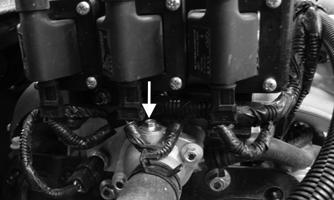
MOD588
2.When pure coolant (no air) flows from the bleed hole, tighten the bleed plug and tighten securely. 3.Fill the cooling system to the cold fill line of the reservoir. Run the engine until the radiator fan engages and disengages after the initial fill; then shut off the engine and recheck coolant level once cool.
NOTE: Use a good quality, biodegradable glycol-
based, automotive-type antifreeze.
RADIATOR Removing 1.Remove the hood; then remove the two cap screws securing the inner portion of the front fenders and the grille.

MODC054
2.Gently lift up on the front fenders where it meets the grille to gain access to the upper headlight cap screw; then remove the upper headlight cap screw; then repeat for other side.

MODC071
CAUTION
When removing radiator hoses, coolant will come out. Use a suitable drain pan or absorbent material to catch and absorb coolant.
3.Loosen and slide back the lower radiator hose clamp on the passenger side; then using a suitable clamp, clamp the hose to minimize coolant leakage; then disconnect the lower hose from the radiator; then loosen and slide back the upper radiator hose clamps on the driver side; then using suitable clamps, clamp the hoses to minimize coolant leakage; then disconnect the upper hoses.

MOD476 MOD475
4.Remove the two cap screws and lock nuts securing the radiator bracket to the frame; then remove the radiator bracket from the vehicle; then disconnect the radiator fan electrical connection.


MOD473

MOD474
5.Lift the radiator assembly from the vehicle. Account for two upper and two lower rubber mounting grommets. Cleaning and Inspecting 1.Flush the radiator with water to remove any contaminants. 2.Inspect the radiator for leaks and damage. 3.Inspect all hoses for cracks and deterioration. 4.Inspect all fasteners and grommets for damage or wear.
Installing 1.Place the radiator into position, making sure the grommets are correctly installed; then install the radiator bracket into the vehicle; then secure the radiator bracket with the two cap screws and lock nuts; then tighten to 20 ft-lb (27.2 N-m); then connect the radiator fan electrical connection.
MOD473
MOD474
2.Connect the lower radiator hose to the radiator; then remove the suitable clamp to minimize coolant leakage; then loosen and slide the radiator hose clamp toward the radiator; then tighten the clamp securing the lower radiator hose to the radiator; then connect the upper radiator hoses to the radiator; then remove the suitable clamps to minimize coolant leakage; then loosen and slide the radiator hose clamp toward the radiator; then tighten the clamp securing the upper radiator hoses to the radiator.
MOD475 MOD476
3.Gently lift up on each front fender where it meets the grille to be able to install the upper headlight cap screw; then install the upper headlight cap screw.
MODC071
4.Install the two cap screws securing the inner portion of the front fenders and the grille.
MODC054
5.Pour the recommended coolant into the coolant reservoir; then bleed the system (see Bleeding Cooling
System in this section).
THERMOSTAT Removing 1.Drain some coolant from the cooling system. 2.Remove the coolant hose from the thermostat housing

MOD551A
3.Located below the coils. Remove the two cap screws securing the thermostat housing.

MOD551C
4.Gently remove the thermostat housing away from the engine. Remove the thermostat. Account for the thermostat housing gasket.

MOD587

MOD586
Inspecting 1.Inspect the thermostat for corrosion, wear, or spring damage. 2.Using the following procedure, inspect the thermostat for proper operation.
A.Suspend the thermostat in a container filled with water.
B.Heat the water and monitor the temperature with a thermometer.
C.The thermostat should start to open at 83-87° C (181-189° F).
D.If the thermostat does not open, it must be replaced. 3.Inspect all coolant hoses, connections, and clamps for deterioration, cracks, and wear. NOTE: All coolant hoses and clamps should be
inspected per the maintenance schedule.
Installing 1.Using a new thermostat housing gasket. Place the thermostat into the thermostat housing.
MOD586
MOD587
2.Install the two cap screws securing the thermostat housing and tighten to 15 ft-lb (20 N-m).
MOD551C
3.Install the coolant hose to the thermostat housing; then pour the recommended coolant into the coolant reservoir; then bleed the system (see Bleeding Cooling System in this section).

MOD551B
COOLING FAN Removing 1.Disconnect the radiator fan electrical connection.
MOD474
2.Remove the four cap screws securing the fan to the radiator fan bracket; then remove the fan from the radiator.

MOD477
Installing NOTE: The fan wiring must be in the upper left
position.
1.Position the fan assembly to the radiator; then install the four cap screws securing the fan to the radiator fan bracket.
MOD477
2.Connect the radiator fan electrical connection.
MOD474
WATER PUMP NOTE: The water pump is only serviceable as an
assembly (see Engine section — Removing Cylinder Head and Related Components).
Troubleshooting
Problem: Starting impaired Condition Remedy
1. Gas contaminated 1.Drain gas tank and fill with clean gas
Problem: Idling or low speed impaired Condition Remedy
1. Throttle body out of sync 1.Diagnose throttle body — Perform full verification on throttle body
Problem: Medium or high speed impaired Condition Remedy
1. Fuel pump obstructed — insufficient pressure 1.Diagnose fuel pump — replace


