
22 minute read
Periodic Maintenance/Tune-Up


Tighten all nuts, bolts, and cap screws. Care must be taken that all calibrated nuts, bolts, and cap screws are tightened to specifications. It is advisable to lubricate certain components periodically to ensure free movement. Apply light oil to the components using the following list as reference:
A.Accelerator Pedal Pivot
B.Brake Pedal Pivot
C.Shift Cable SPECIAL TOOLS A number of special tools must be available to the technician when performing service procedures in this section. Refer to the current Special Tools Catalog for the appropriate tool description. NOTE: When indicated for use, each special tool
will be identified by its specific name, as shown in the chart below, and capitalized.
Description p/n
Drive and Driven Clutch Holder Tool 0444-317 Drive Belt Gauge 0444-177 Hub Retaining Wrench 0444-270
NOTE: Special tools are available from the Service
Department.
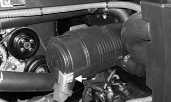
CVT Air Inlet
This vehicle is equipped with an air inlet to collect air for the Continuously Variable Transmission (CVT). NOTE: When servicing clutches or belt, it is recom-
mended to inspect and clean the CVT air inlet.
1.Remove the left-side access panel; loosen the clamp that holds the snorkel portion to the air inlet.
MOD205
2.Disconnect snorkel portion from air inlet; clean and inspect.
Engine Air Filter
Primary Air Filter/Safety Filter/ Clean-out Valve The engine air filter inside the air filter housing must be kept clean to provide good engine power and fuel mileage. If the vehicle is used under normal conditions, service the filter at the intervals specified. If operated in dusty, wet, or muddy conditions, inspect and service the filter more frequently. Use the following procedure to clear the clean-out valve, remove the primary filter and safety filter, and inspect and/or clean them.
CAUTION
Failure to inspect the air filter frequently if the vehicle is used in dusty, wet, or muddy conditions can damage the engine.
NOTE: To access the air filter housing, the right-
side access panel must be removed and the cargo box raised if desired.
REMOVING AND INSPECTING 1.Remove dirt and debris from around the air filter housing cover; then squeeze the clean-out valve to clear it of any accumulated dirt or dust. 2.Check the clean-out valve for cracks or damage.
Replace as needed.

MOD085
3.Pull out on the orange air filter housing cover lock; then turn the air filter housing cover counterclockwise to access the filter.
MOD084A
MOD084B
4.Loosen the clamp indicated and disconnect the snorkel from the housing; then clean and inspect the inside of the snorkel; then remove the primary air filter element; then wipe the inside of the housing to remove dirt and debris.

MOD597

MOD598 MOD086


MOD087
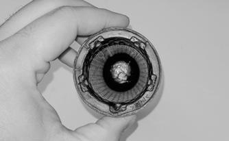
5.Inspect the primary air filter element for damage or dirt. If damaged the filter must be replaced. 6.A dust trail anywhere inside of the air filter housing, inlet tube or on the safety filter is a telltale sign of a leak. Leaks should be inspected by an authorized dealer.
CAUTION
Do not attempt to clean the primary filter or filter damage may occur.
CAUTION
When replacing the primary filter, always inspect the new filter for damage. Never install a damaged filter. Do not wipe the new filter as it is lubricated for sealing purposes.

MOD088
MOD089
7.Remove and inspect the safety filter.


MOD092
2.Install the air filter housing cover with the clean-out valve at the 5 o’clock position; then turn the air filter housing cover clockwise until it seats. NOTE: The clean-out valve should be near the
6 o’clock position when the cover is seated.
3.Lock the air filter housing cover.

MOD090
INSTALLING 1.Install safety filter; then install the primary filter. NOTE: The flower shape of the primary filter ele-
ment must line up with the same-shaped void in the air filter housing for the air filter housing cover to fit properly.
MOD091A MOD084C


MOD084A
4.Connect the snorkel to the housing; then tighten the clamp securely.

MOD597
5.Install the right access panel and secure with two 1/4-turn fasteners.
CAUTION
A torn air filter can cause damage to the engine. Dirt and dust may get inside the engine if the element is torn. Carefully examine the element for tears before and after cleaning it. Replace the element with a new one if it is torn.

Valve Clearance
Checking Valve Clearance NOTE: The engine does not need to be removed
from the vehicle for this procedure.
1.Disconnect the negative battery cable; then remove the valve cover (see REMOVE AND INSTALL
VALVE COVER). NOTE: There are two intake and two exhaust
valves per cylinder. The intake camshaft and valves are next to the intake manifold and the exhaust camshaft and valves are next to the exhaust manifold.
2.Remove the spark plugs, making sure no dirt or foreign material enters the cylinders.

MF034B
3.Using a suitable bar, turn the crankshaft in the direction of rotation until the highest section of the camshaft lobes (A) of the valves to be checked are pointing directly away from the valve bucket (B).
MF039A
MF078A
4.Using a suitable feeler gauge, check clearance between the camshaft and the valve bucket recording the value when a slight drag is felt when inserting and retracting the gauge blade.

MF037
5.Repeat and record clearance values for all remaining valves NOTE: Intake valve clearance specification is 0.18 ±
0.05 mm (0.007 ± 0.002 in.). Exhaust valve clearance specification is 0.25 ± 0.05 mm (0.010 ± 0.002 in.).
6.Install the valve cover (see REMOVE AND
INSTALL VALVE COVER); then connect the battery cables.
Spark Plug
A light brown insulator indicates that the plug and fuel/ air ratio are correct. A white or dark insulator indicates that the engine may need to be serviced. To maintain a hot, strong spark, keep the plug free of carbon.
ATV-0051

CAUTION
Before removing the spark plug, be sure to clean the area around the spark plug. Dirt could enter engine when removing or installing the spark plug.
Adjust the gap to 1.0 mm (± 0.1 mm).
ATV0052
Tighten spark plug to 14.75 ft-lb (20 N-m).
Muffler/Spark Arrester
The muffler has a spark arrester which must be periodically cleaned. At the intervals shown in the Maintenance Schedule, clean the spark arrester using the following procedure.
1.Remove the cap screw securing the spark arrester assembly to the muffler.
! WARNING
Wait until the muffler cools to avoid burns.

MOD095A
2.Using a suitable brush, clean the carbon deposits from the screen taking care not to damage the screen. NOTE: If the screen is damaged in any way, it must
be replaced.
3.Install the spark arrester assembly and secure with the cap screw. Tighten to 60 in.-lb (6.8 N-m).
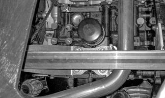
Engine Oil — Filter
Change the engine oil and oil filter at the scheduled intervals. The engine should always be warm when the oil is changed so the oil will drain easily and completely. 1.Park the vehicle on level ground. 2.Remove the maintenance cover to access the oil filter.

MOD105
3.Tilt the cargo box to the dump position; then loosen the oil fill cap. Be careful not to allow contaminants to enter the opening.
MOD064
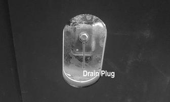
4.Remove the drain plug from the bottom of the engine and drain the oil into a drain pan.


MOD020A
5.Using the oil filter wrench and a ratchet handle (or a socket or box-end wrench), remove the old oil filter and dispose of properly. Capture oil in a suitable pan or absorbent material. Do not re-use oil filter.
Front Differential Lubricant — Transaxle Fluid
INSPECTING/CHANGING Inspect and change the lubricant/fluid in each according to the Maintenance Schedule. Use the appropriate lubricant and the following procedure: 1.Place the vehicle on level ground; then remove the fill plugs on the front differential (A) and transaxle (C).
MOD073A
MOD106
NOTE: Clean up any excess oil after removing the
filter.

6.Apply oil to the new filter O-ring and check to make sure it is positioned correctly; then install the new oil filter. Tighten securely. 7.Install the engine drain plug and tighten to 36.9 ft-lb (50 N-m). Pour the recommended oil into the filler hole. Install oil fill cap. 8.Start the engine (while the vehicle is outside on level ground) and allow it to idle for a few minutes. 9.Turn the engine off and wait approximately one minute. Recheck the oil level. 10.Inspect the area around the drain plug and oil filter for leaks. 11.Install the maintenance cover. 12.Check to make sure the oil fill cap is secure and the oil level stick is installed correctly; then lower the cargo box to its locked down position.
MOD085A
2.Drain the lubricant/fluid into a drain pan by removing the drain plugs from the right-side front differential (E) and transaxle (D).

MOD085A

Headlight — Taillight/ Brake Light
Light Bulb Replacement CAUTION
Use only specified bulbs indicated in the Specifications chart as replacement bulbs.
NOTE: The bulb portion of the headlight is fragile.
HANDLE WITH CARE. When replacing the headlight bulb, do not touch the glass portion of the bulb. If the glass is touched, it must be cleaned with a dry cloth before installing. Skin oil residue on the bulb will shorten the life of the bulb.
To replace the headlight bulb, use the following procedure. 1.Disconnect the wiring harness; then remove the rubber boot from the light assembly.
MOD085A
3.After the lubricant/fluid has been drained, install the drain plugs and tighten to 45 in.-lb (5.1 N-m) (front differential) and 16 ft-lb (21.8 N-m) (transaxle). CAUTION

Inspect the lubricant/fluid for any signs of metal filings or water. If found, take the vehicle to an authorized dealer for servicing.
4.Pour recommended quantity and type of lubricant/ fluid into each fill hole, as follows:
Front differential fill plug (A) — add lubricant until it is level with the lubricant inspection plug (B). Transaxle fill and fluid inspection plug (C) — add fluid until it is level with the bottom of (C). 5.Install the fill plugs and tighten to 16 ft-lb (21.8 N-m) and install the front differential lubricant inspection plug to 45 in-lb (5.1 N-m). NOTE: If the lubricant/fluid is contaminated with
water, inspect the drain plug, fill plug, and/or seals.

Driveshaft/Coupling
The following drive system components should be inspected periodically to ensure proper operation. A.Spline lateral movement (slop). B.Coupling cracked, damaged, or worn.
MOD046
MOD096
CAUTION
When replacing the headlight bulb, be careful not to touch the glass portion of the bulb. Grasp the new bulb with clean rubber gloves.
2.Remove the old H4 bulb by unlocking the spring; then insert the new bulb into headlight assembly and lock the spring to secure the bulb.

MOD097A

3.Install the rubber boot making sure it is sealed around the bulb and connect the wire harness.


MOD098A
4.Adjust the headlight (see Checking/Adjusting Headlight Aim in this sub-section. Taillight/Brake Light Assembly If one or more individual LED bulbs are not working, the taillight/brake light assembly must be replaced.
MOD114A
MOD115A
2.Remove screw (A); then flex the cargo box fender away from the cargo box to access and remove screw (B). NOTE: A long extension with a T25 socket or long
T25 screwdriver will be needed to access screw (B).

MOD096
To replace the taillight/brake light assembly, use the following procedure: 1.Remove the four screws from the inner cargo box side panel, two rear tie-down screws and one tailgate latch bail screw; then remove the six screws from the underside of the cargo box and remove the outer cargo box side panel.

MOD117A
MOD113
3.Remove the taillight/brake light assembly and disconnect it from the harness by pushing on the connector lock.

MOD110


MOD112A
4.Install the new assembly, making sure to connect the harness.
MOD117A
MOD113
6.Position the outer cargo box side panel behind the two tabs on the cargo box fender; then fit all tabs into their adjoining slots in the side panel.

MOD112
5.Install screw (A) first; then flex the cargo box fender away from the cargo box to access and install screw (B).
MOD116A
7.With a suitable pry bar, lift up on the inner cargo box floor near the rear corner.

MOD110A
8.Start at the rear of the cargo box and tuck the outer side panel under the cargo box floor and work it into place from back to front.

MOD111
9.Once the outer side panel is in place, install the screws securing the cargo box fender and outer side panel.

MOD114A

MOD115A
Checking/Adjusting Headlight Aim The headlights can be adjusted vertically. The geometric center of the HIGH beam light zone is to be used for aiming. 1.Position the vehicle on a level floor so the headlights are approximately 6.1 m (20 ft) from an aiming surface (wall or similar aiming surface).
MOD039
NOTE: There should be an average operating load
on the vehicle when adjusting the headlight aim.
2.Measure the distance from the floor to the midpoint of each headlight. 3.Using the measurements obtained in step 2, make horizontal marks on the aiming surface. 4.Make vertical marks which intersect the horizontal marks on the aiming surface directly in front of the headlights. 5.Switch on the lights. Make sure the HIGH beam is on. DO NOT USE LOW BEAM. 6.Observe each headlight beam aim. Proper aim is when the most intense beam is centered on the vertical mark 5 cm (2 in.) below the horizontal mark on the aiming surface. 7. Turn the headlight adjustment cap screw clockwise to adjust the headlight aim down or counterclockwise to adjust the headlight aim up.

MOD046A
Shift Cable
CHECKING SHIFT CABLE Turn the ignition switch on; then shift the transmission into park. The letter P should illuminate on the LCD gauge and the park icon (P) should illuminate. The vehicle should not be able to move.

MOD207
Move the shift lever all the way back. The letter L should illuminate on the LCD gauge.

MOD208
If either park or low range cannot be reached, the shift cable must be adjusted. ADJUSTING SHIFT CABLE 1.Secure the vehicle on a support stand to elevate the wheels; then place the transmission in neutral; then rotate the rear wheels by hand at least two revolutions.
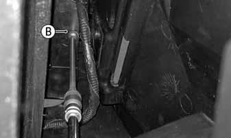
2.Tilt the cargo box up; then remove the passengerside rear inner fender. With the gear selector in neutral, measure the distance on each side of the upper tilt steering wheel adjuster bracket and the shifter housing. ! WARNING
Make sure the vehicle is solidly supported on the support stand to avoid injury.

MOD520
NOTE: If the distance on each side of the upper tilt
steering wheel adjuster bracket and the shifter housing is the same and the vehicle does not properly engage Park or Low, shift cable replacement may be required.
3.Loosen nuts (A) and (B) and adjust the cable housing until the measurements on each side of the upper tilt steering wheel adjuster bracket are the same.

MOD297
4.Tighten the nuts (A) and (B) to 20 ft-lb (27.2 N-m). 5.Check each gear shift position for proper gear selection and make sure the proper icon illuminates on the LCD.
Hydraulic Brake System
NOTE: This ROV/UTV is equipped with hydraulic
brakes at all four wheels.
CHECKING/BLEEDING The hydraulic brake system has been filled and bled at the factory. 1.With the master cylinder in a level position, check the fluid level in the reservoir. If the level in the reservoir is not above the MIN, add DOT 4 brake fluid.

MOD163
2.Depress the brake pedal several times to check for a firm brake. If the brake is not firm, the system must be bled. To bleed the brake system, use the following procedure:
A.Remove the cover and fill the reservoir with DOT 4 brake fluid; then install and secure the cover.
B.Slowly depress the brake pedal several times. C.Install one end of a clear hose onto the RIGHT
REAR bleeder screw and direct the other end into a container; then while holding slight pressure on the brake pedal, open the bleeder screw and watch for air bubbles. Close the bleeder screw before releasing the brake pedal. Repeat this procedure until no air bubbles are present.

MOD299
MOD300

NOTE: During the bleeding procedure, watch the
reservoir very closely to make sure there is always a sufficient amount of brake fluid. When the level falls below MIN, refill the reservoir before the bleeding procedure is continued. Failure to maintain a sufficient amount of fluid in the reservoir will result in air in the system.
D.At this point, perform steps B and C on the REAR LEFT bleeder screw; then move to the FRONT RIGHT bleeder screw and follow the same procedure. Finally, complete the procedure on the FRONT LEFT bleeder screw.
FRONT CAUTION
This hydraulic brake system is designed to use DOT 4 brake fluid only. If brake fluid must be added, care must be taken as brake fluid is very corrosive to painted surfaces.

MOD081A
3.If thickness of either brake pad friction material is less than 0.5 mm (0.019 in.), the brake pads must be replaced. NOTE: The brake pads should be replaced as a set. 4.To replace the brake pads, use the following procedure:
A.Remove the Torx head plug from the caliper; then remove the cap screws securing the caliper holder to the knuckle.
MOD161
E.Repeat steps B and C until the brake pedal is firm. 3.Carefully check the entire hydraulic brake system to ensure all hose connections are tight, the bleed screws are tight, the protective caps are installed, and no leakage is present.

INSPECTING HOSES Carefully inspect the hydraulic brake hoses for cracks or other damage. If found, the brake hoses must be replaced. CHECKING/REPLACING PADS The clearance between the brake pads and brake discs is adjusted automatically as the brake pads wear. The only maintenance that is required is replacement of the brake pads when they show excessive wear. Check the thickness of each of the brake pads as follows. 1.Remove the wheel corresponding to the brake being checked. 2.Measure the thickness of each brake pad.

MOD301
B.Remove the pads from the caliper; then install the new brake pads.

MOD302
C.Secure the caliper holder to the knuckle with new “patch-lock” cap screws. Tighten to 45 ft-lb (61.2 N-m); then install the Torx head plug to the caliper.

MOD301
MOD512
5.Install the wheels and using a crisscross pattern, tighten the wheel nuts in 20 ft-lb (27.2 N-m) increments to a final torque of 100 ft-lb (136 N-m).
6.Burnish the brake pads. BRAKE DISC Using a micrometer, measure the thickness of the brake disc in the contact surface. If thickness is 0.125 in. or less, the disc must be replaced. To replace the brake disc, see Drive System – Hub/Brake Disc.
Burnishing Brake Pads
Brake pads must be burnished to achieve full braking effectiveness. Braking distance will be extended until brake pads are properly burnished. ! WARNING
Do not attempt sudden stops or put yourself into a situation where a sudden stop will be required until the brake pads are properly burnished.
1.Choose an area large enough to safely accelerate the vehicle to 30 mph and to brake to a stop. 2.Accelerate to 30 mph; then release the accelerator pedal and depress the brake pedal to decelerate to 0-5 mph.
Stopping distance should be approximately 50 ft. 3.Repeat procedure 20 times.
! WARNING
Using the Operator’s Manual as a guide, instruct the operator on the proper use, care, burnishing procedure (when brake pads are new), and maintenance of the hydraulic brake system.
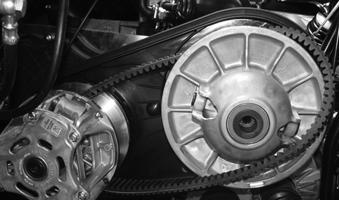
Checking/Replacing Drive Belt
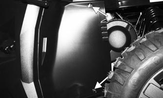
REMOVING 1.Tilt the cargo box up. 2.Remove the rear driver side inner fender by rotating the 1/4-turn fasteners counterclockwise.
MOD606
3.Loosen the clamp that holds the snorkel portion to the air inlet; then disconnect snorkel portion from air inlet.


MOD205A
4.Remove the six clamps securing the clutch cover; then remove clutch cover. NOTE: Firmly grasp clamps as they can completely
detach from clutch cover assembly and spring away.

MOD533
5.Using the Drive and Driven Clutch Holder Tool to hold the driven clutch remove the cap screw securing the driven clutch.

MOD599 MOD215

CHECKING Use the Drive Belt Gauge to identify any abnormal wear. Measure across the top of the drive belt (in multiple locations) using a Vernier caliper. Do not squeeze the belt as doing so may produce an inaccurate measurement. The drive belt must be at least 30 mm (1.18 in.) at any point. INSTALLING NOTE: The arrows on the drive belt should point in
direction of engine rotation (forward).
1.Place the drive belt over the drive clutch and put over the top of the driven sheaves.
MOD216
2.Push in on the outer portion of the driven clutch while rotating counterclockwise. Insert the cap screw with the washer bevel cup side toward the clutch and hand tighten with no tools.

MOD217
3.Continue to push in and rotate the driven clutch counterclockwise while continually tightening the cap screw. 4.When the belt has reached the outermost portion of the driven clutch tighten the cap screw to 60 ft-lb (81.6 N-m) while holding the driven clutch with the
Drive and Driven Clutch Holder Tool.

MOD599

MOD218
5.Rotate the driven clutch counterclockwise at least two times to verify belt is in the outermost portion of the sheave. Torque the cap screw to 60 ft-lb (81.6 N-m) while holding the driven clutch with the Drive and
Driven Clutch Holder Tool
6.The belt should be as shown on the driven sheave.
CAUTION
It is crucial to rotate the driven clutch counterclockwise at least two times and torque the driven cap screw after the initial torque.

MOD219
7.Install the clutch cover making sure the gasket is completely in the grove on the engine side. Install six clamps securing the clutch cover

MOD533
8.Connect clutch air inlet to snorkel portion; then install the clamp that holds the snorkel portion to the air inlet.

MOD205B
9.Reinstall the rear driver-side inner fender and secure by rotating the quarter turn fasteners clockwise.


