58 minute read
Electrical System

The electrical connections should be checked periodically for proper function.
TESTING ELECTRICAL COMPONENTS All electrical tests should be made using the CATT II or the Fluke Model 77 Multimeter. The CATT II can return data for certain components which are identified at the beginning of their respective sub-section. If any other type of meter is used, readings may vary due to internal circuitry. When troubleshooting a specific component, always verify first that the fuse(s) are good, that the gauge is functional, that the connections are clean and tight, that the battery is fully charged, and that all appropriate switches are activated. NOTE: For absolute accuracy, all tests should be
made at room temperature of 68° F.
NOTE: Certain components and sensors can be
checked by using the EFI diagnostic system (see EFI Diagnostic System in this section for more information).
SPECIAL TOOLS A number of special tools must be available to the technician when performing service procedures in this section. Refer to the current Special Tool Catalog for the appropriate tool description. NOTE: When indicated for use, each special tool
will be identified by its specific name, as shown in the chart below, and capitalized.
NOTE: Special tools are available from the Textron
Off Road Service Department.
Description
Diagnostic Harness Fluke Model 77 Multimeter MaxiClips Tachometer CATT II Tool
p/n
0486-219 0644-559 0744-041 0644-275 0544-029
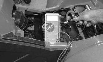
Battery
Component data can be retrieved using the CATT II. Utilize the Sensor Data screen.
NOTE: Preliminary checks may be performed on
this component using the diagnostic mode on the LCD gauge (see EFI Diagnostic System in this section).
After being in service, batteries require regular cleaning and recharging in order to deliver peak performance and maximum service life. The following procedure is recommended for cleaning and maintaining a sealed battery. Always read and follow instructions provided with battery chargers and battery products. NOTE: Refer to all warnings and cautions provided
with the battery or battery maintainer/charger.
Loss of battery charge may be caused by ambient temperature, ignition OFF current draw, corroded terminals, self discharge, frequent start/stops, and short engine run times. Frequent winch usage, snowplowing, extended low RPM operation, short trips, and high amperage accessory usage are also reasons for battery discharge.
Maintenance Charging NOTE: Textron Off Road recommends the use of
the CTEK Multi US 800 or the CTEK Multi US 3300 for battery maintenance charging. Maintenance charging is required on all batteries not used for more than two weeks or as required by battery drain.
800A
1.When charging a battery in the vehicle, be sure the ignition switch is in the OFF position. 2.Clean the battery terminals with a solution of baking soda and water.
NOTE: The sealing strip should NOT be removed
and NO fluid should be added.
3.Be sure the charger and battery are in a well-ventilated area. Be sure the charger is unplugged from the 110-volt electrical outlet.
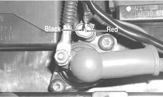
4.Connect the red terminal lead from the charger to the positive terminal of the battery; then connect the black terminal lead of the charger to the negative terminal of the battery. NOTE: Optional battery charging adapters are
available from your authorized dealer to connect directly to your vehicle from the recommended chargers to simplify the maintenance charging process. Check with your authorized dealer for proper installation of these charging adapter connectors.
5.Plug the battery charger into a 110-volt electrical outlet.
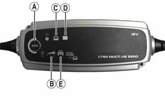
6.If using the CTEK Multi US 800, there are no further buttons to push. If using the CTEK Multi US 3300, press the Mode button (A) at the left of the charger until the Maintenance Charge Icon (B) at the bottom illuminates. The Normal Charge Indicator (C) should illuminate on the upper portion of the battery charger.
NOTE: The maintainer/charger will charge the bat-
tery to 95% capacity at which time the Maintenance Charge Indicator (D) will illuminate and the maintainer/charger will change to pulse/float maintenance. If the battery falls below 12.9 DC volts, the charger will automatically start again at the first step of the charge sequence.
3300C
NOTE: Not using a battery charger with the proper
float maintenance will damage the battery if connected over extended periods.
Charging NOTE: Textron Off Road recommends the use of
the CTEK Multi US 800 or the CTEK Multi US 3300 for battery maintenance charging.
1.Be sure the battery and terminals have been cleaned with a baking soda and water solution. NOTE: The sealing strip should NOT be removed
and NO fluid should be added.
2.Be sure the charger and battery are in a well-ventilated area. Be sure the charger is unplugged from the 110-volt electrical outlet.
3.Connect the red terminal lead from the charger to the positive terminal of the battery; then connect the black terminal lead of the charger to the negative terminal of the battery. 4.Plug the charger into a 110-volt electrical outlet. 5.By pushing the Mode button (A) on the left side of the charger, select the Normal Charge Icon (E). The
Normal Charge Indicator (C) should illuminate on the upper left portion of the charger. 6.The battery will charge to 95% of its capacity at which time the Maintenance Charge Indicator (D) will illuminate.
NOTE: For optimal charge and performance, leave
the charger connected to the battery for a minimum 1 hour after the Maintenance Charge Indicator (D) illuminates. If the battery becomes hot to the touch, stop charging. Resume after it has cooled.
7.Once the battery has reached full charge, unplug the charger from the 110-volt electrical outlet. NOTE: If, after charging, the battery does not perform
to operator expectations, bring the battery to an authorized dealer for further troubleshooting.
Electronic Power Steering (EPS)
Component data and system updates can be retrieved/performed using the CATT II. Navigate the screens as required.
NOTE: Certain models have been produced with
electronic power steering. The following information is intended to be used when servicing these models.
The electronic power steering (EPS) system is an electro-mechanical device that utilizes 12 volt DC power to drive a motor linked to the steering shaft to assist the rider when rotating the handlebar. Rider steering inputs are detected by a torque-sensing transducer assembly within the EPS housing. These inputs are converted to electronic signals by the transducer and control circuitry to tell the motor which way to drive the steering shaft. When no steering input (pressure on the handlebar) is detected, no torque signal is generated, and no steering assist is provided by the motor. If an electrical-related EPS system malfunction occurs, a diagnostic trouble code (DTC) will be displayed on the LCD gauge. Check for updates and verify any active DTCs using the most up-to-date CATT II software. The following is a list of DTCs, possible conditions, and causes.
NOTE: If no active codes are present on the LCD or
verified through CATT II and the vehicle is experiencing steering-related issues, there may be a mechanical steering-related issue. In this case, the EPS is not the cause of the issue. Components that may contribute to this type of issue could be abnormal tire wear, bad wheel bearings, ball joints, tie rod ends, tie rods, or bushings. Check the complete steering system for any sign of wear or misalignment.
NOTE: If any code C1306-C1315 or C1317-C1325
are active and verified with CATT II, EPS replacement is not necessary. Follow the instructions listed in the chart to correct the malfunction.
EPS internal over-current condition has been detected C1302Excessive Current Error EPS internal current measurement error has been detected Internal EPS Condition
C1303Torque Sensor Range Fault EPS internal torque sensor range condition has been detected Internal EPS Condition
C1304Torque Sensor Linearity Fault EPS internal torque sensor linearity condition has been detected Internal EPS Condition
C1305Rotor Position Encoder EPS internal rotor position encoder condition has been detected Internal EPS Condition Correct EPS condition*
Correct EPS condition*
Correct EPS condition*
Correct EPS condition*
C1306System Voltage Low EPS battery power low-voltage condition has been detected
C1307System Voltage High EPS battery power over-voltage condition has been detected System voltage low (less than 11 VDC at the EPS). Wire harness issue, faulty voltage regulator, weak battery or loose battery terminals. EPS will auto-recover when the battery supply returns to normal
System voltage high (more than 16 VDC at the EPS). Wire harness issue, faulty voltage regulator or loose battery terminals. EPS will auto-recover when the battery supply returns to normal
C1308Temperature Above 110° C EPS internal 110° C over-temp condition has been detected
C1309Temperature Above 120° C EPS internal 120° C over-temp condition has been detected
C1310Vehicle Speed High Vehicle speed signal received by the EPS exceeds the maximum speed specification C1311Vehicle Speed Low Vehicle speed signal received by the EPS is zero or missing Debris in EPS housing/cooling fan. Clean the EPS housing and cooling fins. EPS will auto-recover when internal temperature drops below 105° C Debris in EPS housing/cooling fan. Clean the EPS housing and cooling fins. EPS will auto-recover when internal temperature drops below 115° C
Intermittent main harness wires, defective speed-sensor, or intermittent speed sensor wires. EPS will auto-recover when the vehicle speed signal drops below the maximum speed specification
Broken main harness wires, defective speed-sensor, or broken speed sensor wires. EPS will auto-recover when the vehicle speed signal returns to normal
C1312Vehicle Speed Faulty Vehicle speed CAN signal received by the EPS incorrect or missing
C1313Engine RPM High Engine RPM signal received by the EPS exceeds the maximum RPM specification
C1314Engine RPM Low Engine RPM signal received by the EPS suddenly dropped below 500 RPM Broken main harness CAN wires, defective speed-sensor, or broken speed sensor wires. EPS will auto-recover when the vehicle speed signal returns to normal
Intermittent main harness RPM wires, intermittent voltage regulator, intermittent ACG stator wires. EPS will auto-recover when engine RPM signal drops below the maximum RPM specification
Handlebar switch in the “OFF” position, broken main harness RPM wires, defect voltage regulator, broken ACG stator wires. EPS will auto-recover when engine RPM signal returns to normal
C1315Engine RPM Faulty Engine RPM CAN signal received by the EPS incorrect or missing Broken main harness CAN wires or defective ECM.
C1316EEPROM Error EPS internal memory error has been detected Internal EPS condition
C1317CAN Bus Error The EPS has lost CAN communication with the EFI ECM Broken CAN wires in the main harness. EFI ECM connector has been disconnected. EPS will auto-recover when engine RPM signal returns to normal Correct EPS condition*
Correct EPS condition*
C1318Internal CRC Error EPS internal CRC calculation condition has been detected
C1319Boot Counter Exceeded EPS internal application code condition has been detected EPS re-flash has failed. Battery power was lost, or the key switch was turned off, during EPS re-flash programming. EPS must be reprogrammed
Intermittent power has prevented a successful application code launch. Correct EPS power condition*
C1320Incorrect Vehicle Speed-to-RPM Ratio Vehicle speed signal received by the EPS exceeds 10 MPH, but the engine RPM signal less than 500 RPM Intermittent or broken main harness RPM wires, intermittent voltage regulator, intermittent or broken ACG stator wires. Correct EPS condition*
C1321Vehicle Speed Erratic Vehicle speed signal received by the EPS changing at an unrealistic rate Intermittent main harness, intermittent speed sensor, dirty speed senor or trigger wheel. Correct EPS vehicle speed signal condition*
C1322Engine RPM Lost Engine RPM signal received by the EPS exceeds 500 RPM and then is zero or missing Handlebar switch in the “OFF” position, broken main harness RPM wires, defect voltage regulator, broken ACG stator wires. EPS will auto-recover when engine RPM signal returns to normal
C1323“EPS OFF” Gauge Display Battery power has been applied to the EPS for more than 5-minutes, but no engine RPM signal has been detected The EPS has been automatically disabled, after 5-minutes of inactivity, to conserve battery power. EPS will auto-recover when engine is started or the key switch is cycled On-Off-On
C1324Loss of CAN communication with EPS unit The gauge has lost CAN communication with the EPS
C1325Dual Loss EPS loss of both the vehicle speed and the engine RPM signals has been detected
C1326Rotor Position Encoder EPS internal rotor position encoder variance condition has been detected Broken CAN wires in the main harness or disconnected EPS. This is not an EPS generated DTC; gauge DTC display only. Gauge DTC display will clear when the EPS-to-gauge CAN communication is restored.
Handlebar switch in the “OFF” position, the engine stalled (key switch “ON”), broken harness wires, loss of CAN data signal. EPS will auto-recover when either the vehicle speed or engine RPM signal is restored.
Internal EPS Condition Correct EPS condition*
C1327Voltage Converter Error (Low) EPS internal voltage converter low-voltage condition has been detected C1328Voltage Converter Error (High) EPS internal voltage converter over-voltage condition has been detected C1329Internal Data Error EPS internal preloaded data condition has been detected C1400Fuel Level Sensor Circuit OpenThe gauge has lost the correct signal from the level sensor. * After correcting condition, cycle key switch On-Off-On
TROUBLESHOOTING NOTE: The EPS assembly is not serviceable and
must not be disassembled or EPS warranty will be voided.
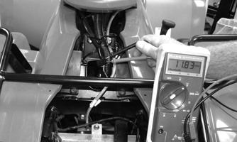
1.Check 30-amp EPS fuse and EPS relay (primary coil: 150 ohms ± 10%, secondary resistance <1 ohm with primary energized). 2.With the ignition off, disconnect 2-pin connector on the EPS assembly and connect a volt meter set to DC voltage to the harness (black meter lead to BLK and red meter lead to ORG/BRN).With the ignition switch in the ON position, the meter should read battery voltage (if correct voltage is not present, check connections and wiring harness).
3.With ignition switch off, disconnect the 8-pin connector on the EPS assembly and connect a volt meter set to DC voltage to the harness (red meter lead to the ORG wire and black meter lead to battery ground.) With the ignition switch in the on position, the meter should read battery voltage (if correct voltage is not present, check for loose fittings or connections in the wiring harness).
CAUTION
Do not attempt to check resistance of the EPS motor (2-pin input receptacle). There are internal capacitors holding a charge that can cause internal damage to an ohmmeter.
CAUTION
If CATT II has confirmed an active DTC relating to the CAN communication wires, use extreme caution when testing the wires. Do not probe the ECM connector with meter leads; instead use a small T-pin or other suitable testing component to make light and proper contact.
CAUTION
Never disconnect the ECM connector with the battery cables installed onto the battery.
NOTE: If after completing the preceding tests and
possible solutions with normal results an EPS issue persists with active DTCs C1301-C1305, 1316, or C1326-C1329 confirmed by CATT II, the EPS assembly must be replaced (see Steering/Body/Controls).
Internal EPS Condition Correct EPS condition*
Internal EPS Condition EPS must be reprogrammed
Open or poor connection in the signal wire or disconnected sensor. Correct fuel level sensor signal wire condition.
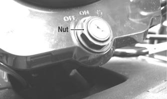
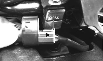
Ignition Switch
The ignition switch harness connects to the switch with a four-pin connector. To access the connector, remove the ignition switch nut, remove the switch, and press the connector release tab. Pull the connector from the switch.
CF272A
CF273A
VOLTAGE NOTE: Perform this test on the harness connector.
1.Set the meter selector to the DC Voltage position. 2.Connect the red meter lead to either red wire; then connect the black meter lead to battery ground. 3.Meter must show battery voltage. NOTE: If the meter shows no battery voltage, trou-
bleshoot the main wiring harness, fuse, or battery.
RESISTANCE NOTE: Perform this test on the switch using the fol-
lowing procedure:
CF274B
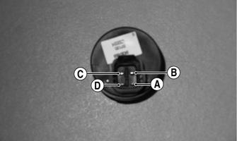
1.Turn the ignition switch to the ON position. 2.Set the meter selector to the OHMS position. 3.Connect either tester lead to pin C; then connect the other tester lead to pin B. 4.The meter must show less than 1 ohm.
5.Turn the ignition switch to the LIGHTS position. 6.Connect either tester lead to pin A; then connect the other tester lead to pin D. 7.The meter must show less than 1 ohm.
8.Connect either tester lead to pin C; then connect the other test lead to pin B. 9.The meter must show less than 1 ohm.
10.With the switch in the OFF position, connect the red tester lead and the black tester lead to each of the remaining pins. The meter must show an open circuit on all pins. NOTE: If the meter shows more than 1 ohm of resis-
tance, replace the switch.
Ignition Coil
The ignition coil is on the frame above the engine. To access the coil, the side panel must be removed.
VOLTAGE Primary Coil 1.Set the meter selector to the DC Voltage position; then disconnect the two wire connector from the coil.
2.Connect the red tester lead to the orange wire and the black tester lead to battery ground. 3.Turn the ignition switch to the ON position. The meter must show battery voltage.
Secondary Coil CAUTION
Disconnect the injector connector(s) before performing the following procedure.
1.Connect the primary ignition coil connector. Remove the spark plug cap from the spark plug.
2.Connect the spark plug cap to Ignition Test Plug or other suitable tool; then ground the tool away from the spark plug hole. While turning the engine over, check for sufficient spark. RESISTANCE
CAUTION
Always disconnect the battery when performing resistance tests to avoid damaging the multimeter.
NOTE: For these tests, the meter selector should be set
to the OHMS position.
Primary Winding 1.Disconnect the coil connector. Connect the red tester lead to either terminal; then connect the black tester lead to the other terminal. 2.Resistance must be less than 1 ohm. NOTE: If the meter does not show as specified, replace
ignition coil.
NOTE: Secondary coil resistance checks are not rec-
ommended. An internal diode in the coil prevents accurate secondary resistance measurements.
Spark Plug Cap 1.Connect the red tester lead to one end of the cap; then connect the black tester lead to the other end of the cap.
AR603D
2.The meter must show 4000-6000 ohms. NOTE: If the meter does not read as specified, replace
the spark plug cap.
Accessory Receptacle/Connector
NOTE: This test procedure is for either the receptacle
or the connector.
VOLTAGE 1.Turn the ignition switch to the ON position; then set the meter selector to the DC Voltage position. 2.Connect the red tester lead to the red/white wire or the positive connector; then connect the black tester lead to battery ground. 3.The meter must show battery voltage. NOTE: If the meter shows no battery voltage, trouble-
shoot the battery, fuse, receptacle, connector, or the main wiring harness.
Component data can be retrieved using the CATT II. Utilize the Sensor Data screen.
The auxiliary switch connector is the two-prong connector on the brake switch lead above the gas tank on the right side. To access the handlebar control connector, remove the access panel. NOTE: The ignition switch must be in the ON posi-
tion.
VOLTAGE (Brake Light) 1.Set the meter selector to the DC Voltage position. 2.Connect the red tester to the orange wire; then connect the black tester lead to the red/blue wire.
Auxiliary 1.Set the meter selector to the OHMS position. 2.Connect the red tester lead to one black wire; then connect the black tester lead to the other black wire.
FI502
Handlebar Auxiliary
FI510
Handlebar
FI489
3.The meter must show battery voltage. NOTE: If the meter shows no battery voltage, trou-
bleshoot the battery, fuse, switch, or the main wiring harness.
NOTE: If the meter shows battery voltage, the main
wiring harness is good; proceed to test the switch/component, the connector, and the switch wiring harness for resistance.
RESISTANCE (Brake Light) NOTE: The brake lever must be compressed for the
handlebar switch test. Also, the ignition switch must be in the OFF position.
FI490
3.When the brake pedal/lever is depressed, the meter must show less than 1 ohm.
NOTE: If the meter shows more than 1 ohm of resis-
tance, replace the switch.
RESISTANCE (HI Beam) The connector is the yellow one next to the steering post. To access the connector, the steering post cover and the right-side fender splash shield must be removed (see Steering/Body/Controls).
NOTE: These tests should be made on the top side
of the connector.
1.Set the meter selector to the OHMS position. 2.Connect the red tester lead to the yellow wire; then connect the black tester lead to the gray wire. 3.With the dimmer switch in the HI position, the meter must show less than 1 ohm.
NOTE: If the meter shows more than 1 ohm of resis-
tance, replace the switch.
RESISTANCE (LO Beam) 1.Connect the red tester lead to the white wire; then connect the black tester lead to the gray wire. 2.With the dimmer switch in the LO position, the meter must show an open circuit. NOTE: If the meter reads resistance, replace the
switch.
DIODE (Starter Button) NOTE: If voltage is not as specified, check the con-
dition of the battery in the meter prior to replacing the switch. A low battery will result in a low voltage reading during a diode test.
1.Set the meter selector to the Diode position. 2.Connect the red tester lead to the orange/white wire; then connect the black tester lead to the yellow/green wire.
3.With the starter button depressed, the meter must show 0.5-0.7 DC volt.
4.With the starter button released, the meter must show .OL.
5.Connect the red tester lead to the yellow/green wire; then connect the black tester lead to the orange/white wire.
6.With the starter button depressed, the meter must show .OL.
NOTE: If the meter does not show as specified,
replace the switch.
RESISTANCE (Engine Stop Switch) 1.Set the meter selector to the OHMS position. 2.Connect the red tester lead to the orange wire; then connect the black tester lead to the orange/white wire.
3.With the switch in the OFF position, the meter must show an open circuit. 4.With the switch in the RUN position, the meter must show less than 1 ohm.
NOTE: If the meter shows more than 1 ohm of resis-
tance, replace the switch.
RESISTANCE (Reverse Override)
Component data can be retrieved using the CATT II. Utilize the Sensor Data screen. Component data can be retrieved using the CATT II. Utilize the Sensor Data screen.
Component data can be retrieved using the CATT II. Utilize the Sensor Data screen.
The connector is the four-prong white one next to the steering post. To access the connector, the front rack and front fenders must be removed (see Steering/Body/Controls). 1.Set the meter selector to the OHMS position. 2.Connect the red tester lead to one red/yellow wire; then connect the black tester wire to the other red/yellow wire. The meter must show less than 1 ohm.
3.Depress and hold the reverse override button. The meter must show an open circuit. 4.Connect the red tester lead to the blue wire; then connect the black meter lead to the black wire. The meter must show an open circuit. 5.Depress and hold the reverse override button. The meter must show less than 1 ohm.
RESISTANCE (Drive Select)
The connector is the three-wire white triangular one in front of the upper steering post. NOTE: Resistance tests should be made with the
switch disconnected.
1.Set the meter selector to the OHMS position. 2.Connect the red tester lead to the green/white wire terminal; then connect the black tester lead to the black wire terminal.
3.With the switch in the 2WD position, the meter must show an open circuit. With the switch in the 4WD position, the meter must show less than 1 ohm. With the switch in the 4WD Lock position, the meter must show less than 1 ohm.
4.Connect the red tester lead to the orange/white wire terminal; then connect the black tester lead to the black wire terminal.
5.With the switch in the 2WD position, the meter must show an open circuit. With the switch in the 4WD position, the meter must show an open circuit. With the switch in the 4WD Lock position, the meter must show less than 1 ohm.
NOTE: If the meter does not show as specified,
replace the drive select switch.
NOTE: If the meter shows other than specified,
check the harness, connector, 30-amp fuse, and battery connections.
RESISTANCE (Gear Position)
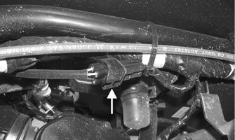
The gear position switch is located on the engine/transmission next to the shift arm.
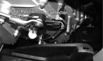
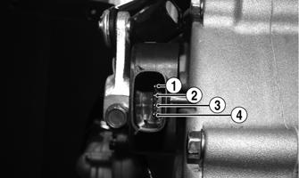
1.Disconnect the gear position switch connector; then using a multimeter, test the switch in each position as follows. Resistance must be less than 1 ohm for all tests.
KC410A
A.Neutral (N)Pins 3 to 4
B.Reverse (R)Pins 3 to 4 and 3 to 2
C.High (H)Pins 3 to 4 and 3 to 1
D.Low (L)Pins 3 to 1 2.Connect the harness to the gear position switch.
Fan Motor
This component can be tested using the CATT II. Utilize the Test screen.
The connector is the black two-prong one located above the oil cooler/radiator.
NOTE: To determine if the fan motor is good, con-
nect the red wire from the fan connector to the positive side of a 12-volt battery; then connect the black wire from the fan connector to the negative side. The fan should operate.
NOTE: Fan motor resistance checks are not recom-
mended. Resistance values change with the motor commutator position.
! WARNING
Care should be taken to keep clear of the fan blades.
Front Drive/Differential Lock Actuator
NOTE: With the engine stopped and the ignition
switch in the ON position, a momentary “whirring” sound must be noticeable each time the drive select switch is moved between positions. The LCD gauge will display 4WD and 4WD Lock in the corresponding switch positions. Test the switch, 30-amp fuse, and wiring connections prior to testing the actuator system.
NOTE: Voltage tests must be made with the switch
and the actuator connected to the main harness. The meter can be connected at the actuator connector using a break-out harness or MaxiClips.
VOLTAGE 1.Turn the ignition switch to the ON position, but do not start the engine. 2.Connect the black tester lead to the black wire.
3.Select the DC Volts position on the tester and observe the meter readings for each of the three switch positions:
WIRE COLOR 2WD 4WD DIFFERENTIAL LOCK
Red to Orange Battery 0 DC Volts 0 DC Volts Voltage
Red to White/Green Battery Voltage Battery Voltage 0 DC Volts
Red to White/Orange Battery Voltage Battery Voltages Battery Voltage
NOTE: If the meter does not show voltages accord-
ing to the chart, make sure the switch and front drive actuator are both plugged into the main harness; then troubleshoot the switch, ignition fuses, battery connections, or wiring harness.
NOTE: If the voltage readings are as specified and
the actuator does not function correctly, replace the actuator (see Drive System/Brake System).
Lights
VOLTAGE (HEADLIGHT) These four 2-prong connectors are plugged into the headlight bulbs (two on each side). NOTE: Perform this test in turn on the main har-
ness side of all four connectors. Also, the ignition switch must be in the LIGHTS position.
NOTE: The LO beam is the outside bulb, and the
HI beam is the inside bulb.
1.Set the meter selector to the DC Voltage position. 2.Connect the red tester lead to one wire; then connect the black tester lead to the other wire.
3.With the dimmer switch in the LO position, test the two outside connectors (LO beam). The meter must show battery voltage. 4.With the dimmer switch in the HI position, test the two inside connectors (HI beam). The meter must show battery voltage. NOTE: If battery voltage is not shown in any test,
inspect the LIGHTS fuse, battery, main wiring harness, connectors, or the left handlebar switch.
VOLTAGE (Taillight) This 3-prong connector is located under the rear fender assembly.
NOTE: Perform this test on the main harness side of
the connector. Also, the ignition switch should be in the LIGHTS position.
1.Set the meter selector to the DC Voltage position. 2.Connect the red tester lead to the white wire; then connect the black tester lead to the black wire.
3.With the ignition key in the LIGHTS position, the meter must show battery voltage. NOTE: If the meter shows no voltage, inspect fuses,
wiring harness, connectors, and switches.
VOLTAGE (Brake Light) NOTE: Perform this test on the main harness side of
the connector. Also, the ignition switch should be in the ON position and the brake (either foot pedal or hand lever) must be applied.
1.Set the meter selector to the DC Voltage position. 2.Connect the red tester lead to the red/blue wire; then connect the black tester lead to the black wire.
3.With either brake applied, the meter must show battery voltage. NOTE: If the meter shows no voltage, inspect fuses,
wiring harness, connectors, and switches.
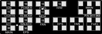
Power Distribution Module (PDM)
The fuses are located in a power distribution module under the seat. If there is any type of electrical system failure, always check the fuses first. NOTE: The ignition switch must be in the LIGHTS
position.
The 4-pin relays are identical plug-in type. Relay function can be checked by switching relay positions. The relays are interchangeable. NOTE: The PDM base and wiring harness are not a
serviceable components and must be replaced as an assembly.
1.Remove all fuses from the distribution module.
2.Set the meter selector to the DC Voltage position. 3.Connect the black tester lead to battery ground. 4.Using the red tester lead, contact each end of the fuse holder connector terminals individually. 5.The meter must show battery voltage from one side of the connector terminal ends.
NOTE: Battery voltage will be indicated from only
one side of the fuse holder connector terminal; the other side will show no voltage.
NOTE: When testing the HI-BEAM fuse holder, the
headlight dimmer switch must be in the HI position; when testing the LIGHTS fuse holder, the headlight dimmer switch can be in either position.
NOTE: If the meter shows no battery voltage, trou-
bleshoot the battery, switches, distribution module, or the main wiring harness.
FUSES NOTE: To access a fuse, compress the locking tabs
on either side of the fuse case and lift out.
3411-968
CAUTION
Always replace a blown fuse with a fuse of the same type and rating.
CAUTION
Always disconnect the battery when performing resistance tests to avoid damaging the multimeter.
Component data can be tested using the CATT II. Utilize the Test screen.
1.Set the meter selector to the OHMS position. 2.Connect the red tester lead to one spade end of the fuse; then connect the black tester lead to the other spade end. 3.The meter must show less than 1 ohm resistance. If the meter reads open, replace the fuse. NOTE: Make sure the fuses are returned to their
proper position according to amperage. Refer to the fuse block decal for fuse placement.
EFI Sensors/Components
FUEL INJECTOR
Voltage Remove the connector from the fuel injector. Place the red meter lead to the orange wire and black meter lead to ground. With the ignition switch in the on position the meter must read battery voltage.
Resistance With the connector still removed from the injector, place the red meter lead to either terminal; then connect the black tester lead to the other terminal. Reading is typically 9.78-10.82 ohms. NOTE: If voltage is not present, troubleshoot the
battery, connector pins, wiring harness, fuses, or relay. If resistance is not present or largely out of specification, replace the injector.
CRANKSHAFT POSITION (CKP) SENSOR 1.Set the meter selector to the OHMS position and test as follows.
WIRE COLOR
Red to White Black to Brown
RESISTANCE
500 Ohms
NOTE: The battery must be at full charge for the
voltage test.
2.Set the meter selector to the AC Voltage position. 3.Connect the red tester lead to the blue wire; then connect the black tester lead to the green wire. 4.Crank the engine over using the electric starter. The meter should read 2.0 or more.
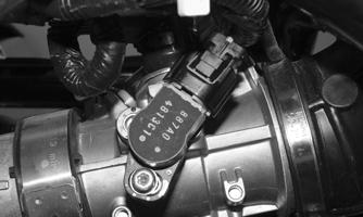
OXYGEN (O2) SENSOR The sensor is located in the exhaust pipe. NOTE: The ambient temperature of the engine and
in the intake and exhaust system must be at room temperature (approximately 68° F) when performing this test or an incorrect reading will occur.
1. On the right side of the ATV, unplug the connector.
CF735A
2. On the sensor side of connector, connect the black (negative) test lead to one white wire pin; then connect the red (positive) test lead to the other white wire pin. 3.With the meter in the OHMS position, the reading should be between 6.7-10.1 ohms.
NOTE: If the meter does not read as specified,
replace sensor.
MANIFOLD ABSOLUTE PRESSURE (MAP) SENSOR
Component data can be retrieved using the CATT II. Utilize the Sensor Data screen. Component data can be retrieved using the CATT II. Utilize the Sensor Data screen.
NOTE: Preliminary checks may be performed on
this component using the diagnostic mode on the LCD gauge (see EFI Diagnostic System in this section).
1.Disconnect the MAP connector from the sensor located on top of the throttle body. 2.Select DC Voltage on the tester and turn the ignition switch to the ON position. 3.Connect the black tester lead to the black/pink wire and the red tester lead to the orange/blue wire. The meter should read 4.5-5.5 DC volts. If the meter does not read as specified, check the ECM connector or wiring. 4.Connect the MAP sensor to the harness; then using
MaxiClips, connect the red tester lead to the brown/white wire and the black tester lead to the black/pink wire. With the engine running at idle speed, the meter should read approximately 2.5 DC volts (MAP sensor signal). NOTE: If the meter does not read as specified,
replace the sensor.
INLET AIR TEMPERATURE (IAT) SENSOR
NOTE: The ambient temperature of the engine and
in the intake and exhaust system must be at room temperature (approximately 68° F) when performing this test or an incorrect reading will occur.
Resistance 1.Disconnect the harness connector from the sensor at the air box assembly. 2.Connect the meter leads (selector in OHMS position) to the IAT sensor terminals.
3.At an ambient air temperature of 68°F, the meter will read approximately 2300 Ohms. NOTE: If the sensor is subjected to a decreased
ambient air temperature, the resulting meter reading will increase. The opposite is true if the ambient air temperature is increased.
NOTE: If the meter does not read as specified,
replace the sensor.
Voltage 1.With the connector still disconnected from the IAT sensor, set the meter to DC volts. 2.Connect the red meter lead to the green/red wire and the black meter lead to ground. With the ignition switch set to the ON position the meter will read approximately 5 DC volts. 3.Connect the red meter lead to the pink/black wire and the black meter lead to ground. With the ignition switch set to the ON position, the meter will read approximately 0.003 DC volts. 4.Connect the harness connector to the IAT sensor, then using Maxi Clips, connect the red tester lead to the green/red wire. Connect the black tester lead to the pink/black wire. With the engine at idle, the meter should read approximately 2.9 DC volts.
NOTE: If the specifications provided in steps 2 and
3 are not observed on the meter, troubleshoot the harness pins, harness wires, or the ECM.
ENGINE COOLANT TEMPERATURE (ECT) SENSOR
Component data can be retrieved using the CATT II. Utilize the Sensor Data screen.
NOTE: Preliminary checks may be performed on
this component using the diagnostic mode on the LCD gauge (see EFI Diagnostic System in this section).
1.Connect the meter leads (selector in OHMS position) to the sensor terminals.
2.Suspend the sensor and a thermometer in a container of cooking oil; then heat the oil. NOTE: Neither the sensor nor the thermometer
should be allowed to touch the bottom of the container or inaccurate readings will occur. Use wire holders to suspend the sensor and thermometer.
! WARNING
Wear insulated gloves and safety glasses. Heated oil can cause severe burns.
TEMPERATURE
-20° C (-4° F) 40° C (105° F) 100° C (212° F)
RESISTANCE
18.8k Ohms 1.14k Ohms 155 Ohms
3.If the readings are not as indicated, the sensor must be replaced. 4.Install the sensor and tighten securely. 5.Connect the leads.
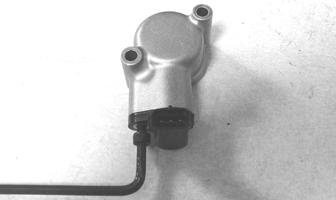
SPEED SENSOR Testing NOTE: Prior to testing the speed sensor, inspect the
three-wire connector on the speed sensor for contamination, broken pins, and/or corrosion.
1.Set the meter selector to the DC Voltage position. 2.With appropriate needle adapters on the meter leads, connect the red tester lead to the orange wire; then connect the black tester lead to the black wire.
3.Turn the ignition switch to the ON position. 4.The meter must show battery voltage. 5.Leave the black tester lead connected; then connect the red tester lead to the pink/white wire. 6.Slowly move the vehicle forward or backward; the meter must show 0 and battery voltage alternately. NOTE: If the sensor tests are within specifications,
the LCD gauge must be replaced.
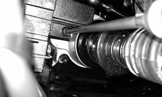
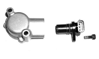
Replacing 1.Disconnect the three-wire connector from the speed sensor harness or from the speed sensor; then remove the cap screw securing the sensor to the sensor housing. 2.Remove the sensor from the sensor housing accounting for an O-ring.
CD070
3.Install the new speed sensor into the housing with new O-ring lightly coated with multi-purpose grease; then secure the sensor with the cap screw (threads coated with blue Loctite #242). Tighten securely.
CD071
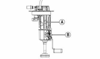
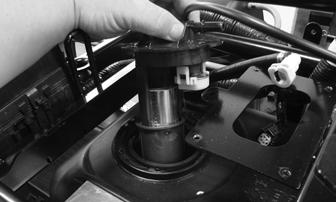
FUEL PUMP/FUEL LEVEL SENSOR
Component data can be retrieved using the CATT II. Utilize the Sensor Data screen.
NOTE: Preliminary checks may be performed on
this component using the diagnostic mode on the LCD gauge (see EFI Diagnostic System in the Electrical System section).
The electric fuel pump and fuel level sensor are not serviceable components. If either component fails, it must be replaced.
TESTING
! WARNING
Whenever any maintenance or inspection is made on the fuel system during which there may be fuel leakage, there should be no welding, smoking, open flames, etc., in the area.
Prior to removing the electric fuel pump, the following check should be performed to determine that removal is necessary.
1.Turn the ignition switch ON and listen for a momentary “whirring” sound of the pump building pressure.
If the sound is heard (10 seconds), no electrical checks are necessary. Turn the ignition switch OFF.
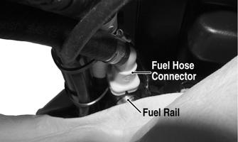
2.Disconnect the fuel hose from the fuel rail; then install a suitable pressure gauge.
! WARNING
Gasoline may be under pressure. Depressurize the fuel system by disconnecting the fuel pump electrical connector and running the engine until it stalls. Place an absorbent towel around the connector to absorb any gasoline when disconnecting.
INSPECTING AT THIS POINT
If the pump has failed earlier test and must be replaced, proceed to INSTALLING.
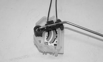
1.Inspect the fuel screen and blow clean with low pressure compressed air. 2.Move the float lever and check for free movement.
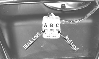
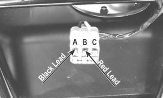
The float assembly should return to the lower position without force. If not, replace the fuel pump assembly. 3.Test the fuel level sensor by connecting a multimeter (A) to the fuel level sensor leads (B); then select
OHMS. The multimeter should show 5 ohms at full fuel position (C) and 95 ohms at empty fuel position (D).
CF691B
3.Reconnect the fuel pump electrical connector; then turn the ignition switch to the ON position. The fuel pressure should build until the pump shuts off. Pressure should read 3.0 kg-cm2 (43 psi). 4.If the pump is not running, disconnect the fuel pump/sensor connector. 5.Connect a multimeter to the power supply leads with the red tester lead to the orange/red wire and the black tester lead to the black wire; then turn the ignition switch to the ON position. The meter should read battery voltage. If battery voltage is indicated and the fuel pump does not run, replace the pump assembly. If no battery voltage is indicated, check the ECM and the vehicle tilt sensor.
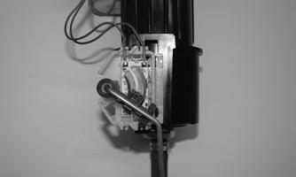
REMOVING 1.Remove the rear rack and fenders (see Steering/Body/Controls); then disconnect the power supply/fuel hose connector. 2.Disconnect the fuel hose and fuel pump connector. 3.Remove the screws securing the fuel pump to the gas tank; then make a reference mark on the fuel pump and tank.
4.Lift out the fuel pump assembly carefully tilting it forward to clear the voltage regulator; then guide the pump and float lever through the opening in the gas tank.
CAUTION
ATV2116
NOTE: If readings are erratic, clean the resistor
wiper and resistor with clean alcohol and retest. If still not correct, replace the fuel level sensor.
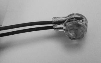
Replacing Fuel Level Sensor To replace the fuel level sensor, use the following procedure:
1.Cut the two blue wires (A) in the location shown. 2.Slide the existing fuel level sensor assembly (B) up and off the fuel pump assembly housing.
XR257A
3.Keeping the float attached to the float arm; then remove the float arm from the existing fuel level sensor. Press the float arm into the new fuel level sensor assembly. Ensure it locks into place.
XM366
NOTE: Inspect the float for any damage or leaking
by submerging in water and looking for any air bubbles. Replace if damaged.
4.Install the fuel level sensor assembly onto the fuel pump assembly housing. Once inserted, press down to make sure it locks into place.
XR258
5.Shorten the wires from the fuel level sensor to approximately the same length as the previously used sensor.
6.Connect the blue wires using the supplied splice connectors from the fuel level sensor kit. Secure the wires.
XM450
INSTALLING 1.Mark the new fuel pump with a reference mark in the same location as the removed pump; then place the new gasket on the pump. 2.Remove the material covering the fuel pump opening; then carefully guide the fuel pump into position taking care not to damage the float or float lever.
XR322
3.Rotate the fuel pump until the match marks align; then install the mounting screws and tighten securely using a crisscross pattern. NOTE: It is critical to install the fuel pump with the
correct orientation to ensure adequate float lever clearance.
4.Connect the wires and fuel hose; then turn the ignition switch to the ON position. Note that the fuel pump runs momentarily and the fuel gauge indicates the proper fuel level. 5.With the transmission in neutral and brake lever lock engaged, start the engine and check for normal operation. Check for any fuel leaks. 6.Install any wire ties that were removed; then install the rear fenders, rack, and seat making sure the seat locks securely.
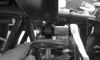
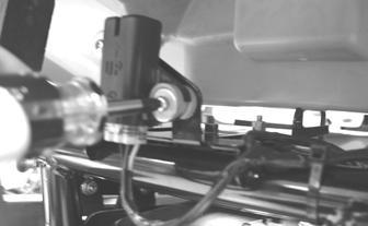
TILT SENSOR The tilt sensor is located below the taillight.
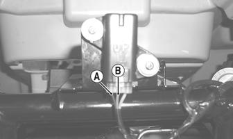
Supply Voltage 1.Disconnect the three-wire connector from the sensor; then select DC Voltage on the multimeter and connect the red tester lead to the orange wire (C) and the black tester lead to the black wire (A).
! WARNING
Incorrect installation of the tilt sensor could cause sudden loss of engine power which could result in loss of vehicle control resulting in injury or death.
CAUTION
Do not drop the tilt sensor as shock can damage the internal mechanism.
2.Turn the ignition switch to the ON position. The multimeter should read battery voltage. If battery voltage is not indicated, check the 30-amp main and 10-amp ignition fuses, wiring harness, or the ignition switch.
3.Remove the red tester lead and connect to the blue/brown wire (B). The multimeter should read 0.2
DC volts or less. If the specified voltage is not indicated, check wire connections at the ECM or substitute another ECM to verify the test.
CD706B
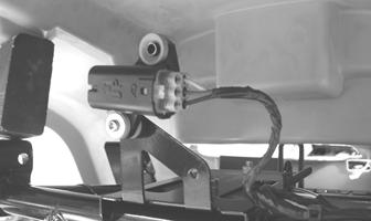
Output Voltage NOTE: Needle adapters or a “break-out” harness
will be required on the multimeter leads as the following tests are made with the sensor connected:
1.Connect the three-wire plug to the sensor; then remove the right-side mounting screw securing the sensor to the rear frame.
CD707
2.Install the needle adapters to the multimeter leads; then select DC Voltage on the multimeter. 3.Connect the red tester lead to the blue/brown wire (B) and the black tester lead to the black/yellow wire (A); then turn the ignition switch ON and observe the meter. The meter should read 0.3-2.9 DC volt.
CD705B
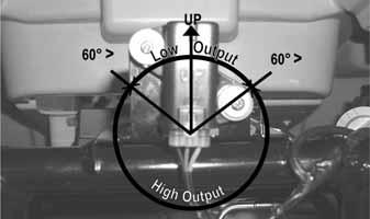
4.Tilt the sensor 60° or more to the left and right observing the meter. The meter should read 3.0-8.0
DC volts after approximately one second in the tilted position. If the meter readings are not as specified, the tilt sensor is defective.
CD709
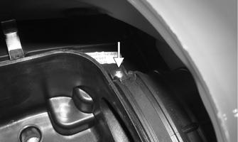
NOTE: When replacing the sensor after testing,
make sure the arrow marking is directed up.
CD705A
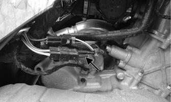
THROTTLE POSITION SENSOR (TPS)
Component data can be retrieved using the CATT II. Utilize the Sensor Data screen.
NOTE: Preliminary checks may be performed on
this component using the diagnostic mode on the LCD gauge (see EFI Diagnostic System in this section).
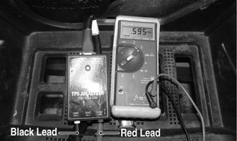
Verifying TPS Adjustment Tool Before using the TPS adjustment tool, verify its battery condition. The battery used in the tool is a 9-volt battery. To check battery condition, use a digital volt/ohmmeter set on DC volt scale. Test between the adjustment tool black and red jacks. Insert the red lead of the digital voltmeter into the red jack of the adjustment tool and the black lead of the digital voltmeter into the black jack of the adjustment tool. The green power light of the analyzer should now be illuminated. If voltage is found below 4.9 volts, replace the battery. NOTE: The Test Harness must be plugged into the
analyzer for testing voltage. Always verify battery voltage is at least 4.9 DC volts before testing TPS.
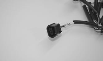
Testing 1.Remove the seat, side covers, front rack, and front body panel (see Steering/Body/Controls); then remove the air filter assembly. 2.Disconnect the TPS connector plug.
XR411
NOTE: Prior to testing the TPS, inspect the
three-wire plug connector on the main harness and the three-pin plug on the TPS for contamination, broken pins, and/or corrosion.
NOTE: If the vehicle is in warranty, removing or
adjusting the TPS will void warranty. If the TPS is tested out of specification, the throttle body must be replaced. If the vehicle is out of warranty, the TPS may be adjusted.
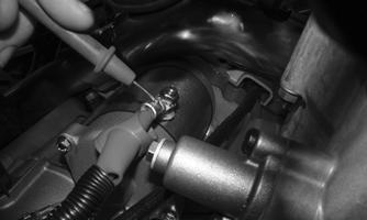
3.Connect the TPS Multi-Analyzer Harness connector #8 to the TPS; then connect the harness to the TPS
Analyzer Tool.
XR410
4.Connect the black test lead to the (VAR) and the red test lead into the (+5V) sockets on the analyzer.
Select the DC Voltage position on the multimeter.
With the vehicle off and the throttle plate fully closed, the gauge should read 0.58-0.62 DC volts and at Wide-Open Throttle it should read up to approximately 3.7 DC volts.
CF329A
Adjusting 1.Loosen the screw securing the TPS to the throttle body. 2.Adjust the TPS until the correct reading is obtained; then tighten the screw securely. Open and close the throttle and determine the reading at idle the correct voltage. Readjust as necessary. 3.Tighten the mounting screw securely. NOTE: If the throttle body, ECM, TPS, or ISC are
replaced, the EFI system must be synchronized. Use the following procedure:
1.With the key off, depress throttle lever to Wide Open
Throttle (WOT). 2.Place the ignition key in the ON position and wait for 10 seconds. 3.Release the throttle lever and wait an additional 10 seconds. 4.Turn the key to the OFF position and allow the gauge to shut off.
RPM Limiter
Component data can be retrieved using the CATT II. Utilize the Sensor Data screen.
NOTE: The ATV is equipped with an ECM that
cuts fuel spray and spark when maximum RPM is approached. When the RPM limiter is activated, it could be misinterpreted as a high-speed misfire.
Gear Park Neutral Reverse High/Low Fail-Safe Mode
2WD 4WD 4000 4WD Lock 2250 6500 2WD Override 5000 4WD Override Differential-Lock
Override 7250 4000
VOLTAGE (AC Generator — No Load) The connector is a three-pin one in the harness coming from the generator.
CF651A
NOTE: Test the connector that comes from the
engine.
1.Set the meter selector to the AC Voltage position. 2.Test between the three black wires for a total of three tests.
3.With the engine running at a constant 5000 RPM, voltage must be approximately 60 volts.
CAUTION
Do not run the engine at high RPM for more than 10 seconds.
NOTE: If the voltage test fails, check the rotor
before replacing the stator.
RESISTANCE (AC Generator) 1.Set the meter selector to OHMS position. 2.Test between the three black wires for a total of three tests.
3.The meter reading must be within specification. NOTE: If the stator coil test failed, check all connec-
tions, etc., and test again. If no voltage is present, but resistance passes, check the physical condition of the rotor/flywheel. If the physical condition is good, replace the stator assembly.
Regulator/Rectifier
The regulator/rectifier is located under the rear rack and rear fenders.
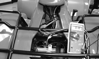
TESTING 1.Start engine and warm up to normal operating temperature; then connect a multimeter to the battery as follows. 2.Select the DC Voltage position; then connect the red tester lead to the positive battery post and the black tester lead to battery ground. 3.Start the engine and slowly increase RPM. The voltage should increase with the engine RPM to a maximum of 15.5 DC volts.
CAUTION
Do not run the engine at high RPM for more than 10 seconds.
NOTE: If voltage rises above 15.5 DC volts, the reg-
ulator is faulty or a battery connection is loose or corroded. Clean and tighten battery connections or replace the regulator/rectifier. If voltage does not rise, see Stator Coil/Crankshaft Position (CKP) Sensor Voltage in this section. If charging coil voltage is normal, replace the regulator/rectifier.
Starter Motor
NOTE: The starter motor is a non-serviceable com-
ponent. If the following test does not result as specified, the starter motor must be replaced.
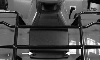
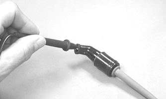
TESTING VOLTAGE Perform this test on the starter motor positive terminal. To access the terminal, slide the boot away. NOTE: The ignition switch must be in the ON posi-
tion, the engine stop switch in the RUN position, and the shift lever in the NEUTRAL position.
1.Set the meter selector to the DC Voltage position. 2.Connect the red tester lead to the starter motor terminal; then connect the black tester lead to battery ground. 3.With the starter button depressed, the meter must show battery voltage and the starter motor should operate.
XR327
NOTE: If the meter showed correct voltage but the
starter motor did not operate or operated slowly, troubleshoot all starting system components before replacing the starter motor.
NOTE: If the meter showed no voltage, inspect the
main fuse, ground connections, starter motor lead, battery voltage (at the battery), starter relay, or the neutral start relay.
2.Remove the nut securing the positive cable to the starter motor; then remove the cable from the starter motor.
3.Remove the two cap screws securing the starter motor to the crankcase; then remove the starter motor. Account for the wiring forms and an O-ring.
CAUTION
Always disconnect the negative battery cable from the battery first; then disconnect the positive cable.
INSTALLING 1.Apply a small amount of grease to the O-ring seal on the starter motor; then install the starter motor into the crankcase. Secure with two machine screws and wiring forms. 2.Secure the positive cable to the starter motor with the nut.
3.Connect the battery (positive cable first).
Starter Relay
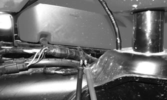
1.Remove the seat; then using the multimeter set to the
DC Voltage position, check the relay as follows. 2.Connect the red tester lead to the positive battery terminal; then connect the black tester lead to the starter cable connection on the starter relay. The meter must show battery voltage.
FI496
NOTE: Make sure that the ignition switch is in the ON
position, transmission in neutral, brake lock released, and the engine stop switch in the RUN position.
3.Depress the starter button while observing the multimeter. The multimeter should drop to 0 volts and a
“click” should be heard from the relay. NOTE: If a “click” is heard and more than 1 volt is
indicated by the multimeter, replace the starter relay. If no “click” is heard and the multimeter continues to indicate battery voltage, proceed to step 4.
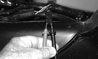
4.Disconnect the two-wire plug from the starter relay; then connect the red tester lead to the yellow/green wire and the black tester lead to the green wire.
KX059A
5.Depress the starter button and observe the multimeter. NOTE: If battery voltage is indicated, replace the
starter relay. If no voltage is indicated, proceed to Power Distribution Module (PDM) check in this section.
Electronic Control Module (ECM)
The electronic control module (ECM) is located beneath the seat near the battery. NOTE: The ECM is not a serviceable component. If
the unit is defective, it must be replaced.
The ECM is rarely the cause for electrical problems; however, if the ECM is suspected, substitute another ECM of the same part number to verify the suspected one is defective.
Codes can be cleared by following the procedures located in EFI Diagnostic System in this section. NOTE: If the throttle body, ECM, TPS, or ISC are
replaced, the EFI system must be synchronized. Use the following procedure:
1.With the key off, depress throttle lever to Wide Open
Throttle (WOT). 2.Place the ignition key in the ON position and wait for 10 seconds.
3.Release the throttle lever and wait an additional 10 seconds.
4.Turn the key to the OFF position and allow the gauge to shut off.
EFI Diagnostic System
DIGITAL GAUGE The digital gauge can be used as a diagnostic tool for many of the DTCs displayed. To place the gauge into the diagnostic mode, use the following procedure: NOTE: Some ATVs may be equipped with a differ-
ent gauge; however, the functionality of the EFI Diagnostic System as depicted remains consistent with the following information.
1.Turn the ignition switch ON. 2.Depress and hold both Mode and Set buttons together for approximately 10 seconds after which the letters “dIAg” will appear on the LCD momentarily followed by COOL.
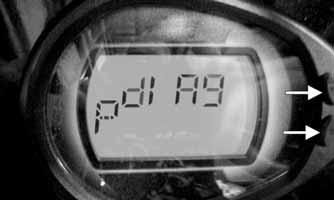
EFI002A
NOTE: The display on the gauge will display in SAE
(speedometer in MPH mode) or Metric (speedometer in km/h mode), For example to read temperature in degrees Celsius, select km/h mode on the gauge or to read Fahrenheit, select MPH mode.
3.Cycle the display by depressing either the Set or
Mode button to step to the desired function.
EFI004
NOTE: The gauge can be utilized dynamically
(engine running/vehicle moving) or statically (engine/vehicle stopped).
Examples of Static checks: Battery voltage, fuel gauge/sensor, and TPS (0% @ closed throttle, 95-100% @ WOT). Examples of Dynamic checks: Battery charging, coolant temperature including fans ON/OFF (see below), MAP/IAT, tachometer, and speedometer signal.
EFI003
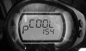
Coolant (COOL) Diagnostic Mode
EFI 003
Display: Engine coolant temperature as measured by the ECT sensor.
DTC: P0116, P0117, P0118, P0119 Usage: Monitor coolant temperature to verify the following: 1.ECT sensor signal 2.High Temperature indicator (on @ 230° F.) 3.Thermostat opening @ approximately 149° F, indicated by a momentary drop or pause in the rising temperature reading. 4.Fan ON @ 185° F, OFF @ 176° F.
A.fan motor
B.fan relay C.fan fuse
D.wiring connections 5.High Temperature Rev Limiter 5000 RPM @ 230° F.
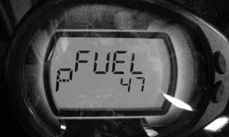
EFI010
Display: Fuel level signal from the fuel level sensor (measured in ohms). DTC: C1400, C1401, C1402 Usage: Check output of the fuel level sensor 1.Full fuel is indicated by a reading of 0-26 ohms 2. Empty is indicated by a reading of 100-105 ohms
* 110-500 ohms, suspect the fuel level sensor or wiring * 0-100 ohms but no fuel gauge indication, suspect the fuel gauge
Tachometer (tACH) Diagnostic Mode
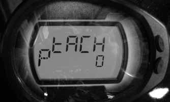
EFI009
Display: Engine RPM DTC: P0336, P0337, P0339 Usage: Verify engine speed signal from the following: 1.CKP (crankshaft position) sensor to ECM 2. ECM (CAN) signal to gauge (tachometer) 3. ECM (CAN) signal to EPS
EFI008
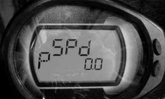
Display: Vehicle speed signal. DTC: P0500
Usage: Verify speedometer sensor signal from the following: 1.Speed sensor to ECM. 2.ECM (CAN) signal to gauge (speedometer/odometer). 3.ECM (CAN) signal to EPS unit.
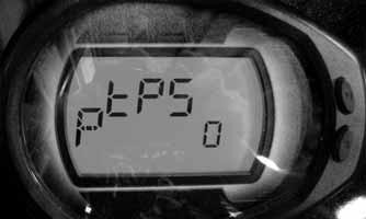
TPS (tPS) Diagnostic Mode
EFI007
Display: % of TPS (0% closed, 95-100% WOT). DTC: P0121, P0122, P0123 Usage: Verify TPS signal and adjust throttle cable.
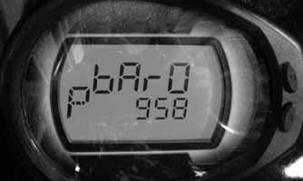
MAP (bArO) Diagnostic Mode
EFI006
Display: MAP in millibars (958 millibar = 28.28 in. mercury). DTC: P0107, P0108
Usage: Verify barometric pressure signal correct. Note: Local barometric pressure is given in in./Hg
(Inches of Mercury). 34 millibars are equal to 1 inch of mercury. Example: (Gauge reading in the BARO mode = 974 millibars, thus 974/34 = 28.64 in./Hg). Second example: (Local barometer reading is 29.87 in./Hg, therefore 29.87 X 34 = 1015 millibars). The gauge should be reading very close to 1015.
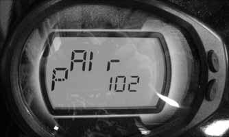
Inlet Air Temperature (AIr) Diagnostic Mode
EFI005
Display: Inlet air temperature in Fahrenheit or Celsius. DTC: P0112, P0113, P0114 Usage: Verify correct output of IAT sensor. NOTE: After engine has been running, IAT read-
ings will be higher than outside air temperature due to engine and engine compartment heat as well as intake manifold heating.
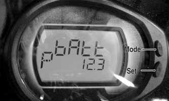
EFI004
Display: System DC voltage. DTC: P0562, P0563, P2531, P2532 Usage: Verify system voltage under following conditions: 1.Battery voltage with engine and accessories off (>12.2 VDC for fully charged). 2.Battery voltage with engine running (charging = 13.8
VDC or greater). 3.Battery voltage with electrical accessories operating, engine idling (13.5 VDC or greater). 4.Battery voltage starter cranking (10.5-11.5 VDC).
DIAGNOSTIC TROUBLE CODES (DTC) If an EFI or related chassis component fails or an out-of-tolerance signal is detected by the ECM, a diagnostic trouble code (DTC) will be generated in the ECM and displayed on the LCD. The DTC will be displayed alternately with a wrench icon or malfunction indicator light (MIL). The DTC will continue to flash, until the malfunction is corrected and the code cleared.
Code List NOTE: Each of the following numerical codes will
have a one-letter prefix of C, P, or U. A “C” prefix denotes a chassis malfunction, a “P” prefix denotes a power train malfunction, and a “U” prefix denotes a CAN communication related code.
NOTE: Normal malfunction codes are cleared from
the LCD when the component is replaced or the malfunction is corrected; however, intermittent codes must be cleared as noted in the code chart.
Code Fault Description Possible Cause Fault Recovery Method
C0063 Tilt Sensor Circuit High Sensor or interconnect harness shorted to battery power Correct condition* C0064 Tilt Sensor Circuit Low/SG/Open Sensor or interconnect harness open or shorted to chassis ground Correct condition* C1400 Fuel Level Sensor Circuit Open Sensor or interconnect harness open or intermittent Correct condition* P0030 O2 Heater Intermittent/Open Heater or interconnect harness intermittent or open Correct condition* P0031 O2 Heater Low/SG Heater or interconnect harness shorted to chassis ground Correct condition* P0032 O2 Heater High/SP Heater or interconnect harness shorted to battery power Correct condition* P0107 MAP Sensor Circuit Low/SG/Open Sensor or interconnect harness shorted to chassis ground Correct condition* P0108 MAP Sensor Circuit High/SP Sensor or interconnect harness shorted to battery power Correct condition* P0112 IAT Sensor Circuit Low/SG Sensor or interconnect harness shorted to chassis ground Correct condition* P0113 IAT Sensor Circuit High/Open Sensor or interconnect harness open or shorted to battery power Correct condition* P0114 IAT Sensor Circuit Intermittent Sensor or interconnect harness intermittent Correct condition* P0116 ECT Sensor Circuit Range/Performance Sensor producing an out-of-range voltage Correct condition* P0117 ECT Sensor Circuit Low/SG Sensor or interconnect harness shorted to chassis ground Correct condition* P0118 ECT Sensor Circuit High/Open/SP Sensor or interconnect harness open or shorted to battery power Correct condition*
P0121 TPS Range/Performance P0122 TPS Circuit Low/SG P0123 TPS Circuit High P0130 O2 Sensor Intermittent/Open Sensor producing an out-of-range voltage
Correct condition* Sensor or interconnect harness shorted to chassis ground Correct condition* Sensor or interconnect harness open or shorted to battery power Correct condition* Sensor or interconnect harness intermittent or open Correct condition*
P0131 O2 Sensor Low/SG or Air-Leak Sensor or interconnect harness shorted to chassis ground or an air-leak exists Correct condition*
P0132 O2 Sensor High/SP Sensor or interconnect harness shorted to battery power Correct condition* P0171 O2 Feedback Below Minimum Correction Low fuel rail pressure, dirty fuel filter, or dirty injectors Correct condition* P0172 O2 Feedback Exceeds Maximum Excessive fuel rail pressure, MAP or temp sensors out-of-spec Correct condition* Correction P0219 Engine Over-Speed Condition Engine speed (RPM) has exceeded the ECM over-speed Reduce engine speed setpoint/limit P0231 Fuel Pump Relay Circuit Low/SG/Open Relay has been removed or interconnect harness shorted to chassis Correct condition* ground P0232 Fuel Pump Relay Circuit High Relay or interconnect harness shorted to battery power Correct condition* P0233 Fuel Pump Relay Circuit Relay circuit erratic or intermittent Correct condition* P0261 Rear Cylinder Fuel injector Circuit Low/SG Injector or interconnect harness shorted to chassis ground Correct condition** P0262 Rear Cylinder Fuel injector Circuit High Injector or interconnect harness shorted to battery power Correct condition** P0263 Rear Cylinder Fuel injector Balance/Open Injector has been disconnected or interconnect harness open Correct condition** P0264 Front Cylinder Fuel injector Circuit Low/SGInjector or interconnect harness shorted to chassis ground Correct condition** P0265 Front Cylinder Fuel injector Circuit High Injector or interconnect harness shorted to battery power Correct condition** P0266 Front Cylinder Fuel injector Balance/Open Injector has been disconnected or interconnect harness open Correct condition** P0336 Crankshaft Angle Sensor Synchronization Sensor or interconnect harness intermittent Correct condition** P0337 Crankshaft Angle Sensor Circuit/SG Sensor or interconnect harness shorted to chassis ground Correct condition** P0339 Crankshaft Angle Sensor Sensor or interconnect harness intermittent Correct condition** Intermittent/Erratic P0340 Camshaft Angle Sensor Synchronization Sensor or interconnect harness intermittent Correct condition** P0341 Camshaft Angle Sensor Circuit/SG Sensor or interconnect harness shorted to chassis ground Correct condition** P0342 Camshaft Angle Sensor Intermittent/ErraticSensor or interconnect harness intermittent Correct condition** P0480 Fan-Primary/Right Relay Control Circuit Relay erratic or intermittent Correct condition* P0481 Fan-Secondary/Left Relay Control Circuit Relay or interconnect harness shorted to battery power Correct condition* High P0482 Fan-Secondary/Left Relay Control Circuit Secondary fan fuse has blown, the secondary fan relay has been Correct condition* Low/SG/Open removed or interconnect harness shorted to chassis ground P0483 Fan-Secondary/Left Relay Control Circuit Relay erratic or intermittent Correct condition* P0484 Fan-Primary/Right Relay Control Circuit Relay or interconnect harness shorted to battery power Correct condition* High P0485 Fan-Primary/Right Relay Control Circuit Primary fan fuse has blown, the primary fan relay has been removed Correct condition* Low/SG/Open or interconnect harness shorted to chassis ground P0500 Vehicle Speed-Sensor Sensor circuit signal intermittent or missing Correct condition*, start and drive the vehicle*
P0508 IAC System Circuit Low/SG
IAC interconnect harness shorted to chassis ground P0509 IAC System Circuit High/Open IAC disconnected or the interconnect harness shorted to battery power Correct condition* Correct condition*
P0520 Engine Oil Sensor/Switch Sensor or interconnect harness erratic or intermittent Correct condition*
P0562 System Voltage Low P0563 System Voltage High Battery charge condition low or the regulator/rectifier output low Correct condition* Battery cable connections are loose or the regulator/rectifier output high Correct condition*
P0601 ECM CAN Communication Shutdown Intermittent CAN connection or unstable CAN condition caused ECM to temporarily shut down CAN communication Correct CAN communication issue*
P0615 Starter Relay Circuit Start switch/button, starter relay, gear switch or interconnect harness erratic or intermittent Correct condition*
P0616 Starter Relay Circuit Low
P0617 Starter Relay Circuit High
Start switch/button, starter relay or interconnect harness intermittent or shorted to chassis ground Start switch/button, starter relay or interconnect harness intermittent or shorted to battery power P0630 VIN Not Programmed or Incompatible Verify the LCD gauge and ECM part numbers are correct for the vehicle model number and VIN Correct condition*
Correct condition*
Correct gauge and ECM VIN compatibility issue*
P0642 Sensor Power Circuit Low P0643 Sensor Power Circuit High P2300 Rear Ignition Coil Primary Circuit Low/SG/Open One or more of the sensors defective or shorted to chassis ground Correct condition* One or more of the sensors defective or shorted to battery power Correct condition* Coil or interconnect harness open or shorted to chassis ground Correct condition**
P2301 Rear Ignition Coil Primary Circuit High Coil or interconnect harness shorted to battery power Correct condition**
P2303 Front Ignition Coil Primary Circuit Low/SG/Open Coil or interconnect harness open or shorted to chassis ground Correct condition**
P2304 Front Ignition Coil Primary Circuit High Coil or interconnect harness shorted to battery power Correct condition**
P2531 Ignition Switch Circuit Low Battery charge condition low or the regulator/rectifier output low Correct condition*
P2532 Ignition Switch Circuit High Battery cable connections are loose or the regulator/rectifier output high Correct condition*
U0155 LCD Gauge to EFI/ECM/CAN Communication Lost Gauge CAN circuit or interconnect harness intermittent or has failed Correct condition*
U1000 Vehicle Not Registered or Invalid PIN An invalid registration PIN has been entered Enter the correct Entered registration PIN* U1001 Vehicle Not Registered An invalid registration PIN has been entered Enter the correct registration PIN* FUEL OFFTilt Sensor Activation Code Sensor has been activated Restore the vehicle chassis to an upright position*
High: A high voltage condition has been detected Low: A low voltage condition has been detected Intermittent: An intermittent circuit condition has been detected Open: An open circuit condition has been detected * After correcting the condition, cycle the key switch On-Off-On **After correcting the condition, cycle the key switch On-Off-On, start the engine, then cycle the key switch On-Off-On.
Troubleshooting
Problem: Spark absent or weak Condition Remedy
1. Ignition coil defective 2. Spark plug defective 3. Magneto defective 4. ECM defective 5. Pick-up coil defective 1.Replace ignition coil 2.Replace plug 3.Replace stator coil 4.Replace ECM 5.Replace stator coil
Problem: Spark plug fouled with carbon Condition Remedy
1. Gasoline incorrect 2. Air cleaner element dirty 3. Spark plug incorrect (too cold) 4.Valve seals cracked — missing 5. Oil rings worn — broken 1.Change to correct gasoline 2.Clean element 3.Replace plug 4.Replace seals 5.Replace rings
Problem: Spark plug electrodes overheat or burn Condition Remedy
1. Spark plug incorrect (too hot) 2. Engine overheats 3. Spark plug loose 1.Replace plug 2.Service cooling system 3.Tighten plug
Problem: Battery does not charge Condition Remedy
1. Lead wires/connections shorted — loose — open 2. Magneto coils shorted — grounded — open 3. Regulator/rectifier defective
1.Repair — replace — tighten lead wires 2.Replace magneto coils 3.Replace regulator/rectifier
Problem: Battery charges, but charging rate is below the specification Condition Remedy
1. Lead wires shorted — open — loose (at terminals) 2. Stator coil (magneto) grounded — open 3. Regulator/rectifier defective 4. Cell plates (battery) defective 1.Repair — tighten lead wires 2.Replace stator coil 3.Replace regulator/rectifier 4.Replace battery
Problem: Battery overcharges Condition Remedy
1. Internal battery short circuited 2. Regulator/rectifier resistor damaged — defective 3. Regulator/rectifier poorly grounded 1.Replace battery 2.Replace resistor 3.Clean — tighten ground connection
Problem: Charging unstable Condition Remedy
1. Lead wire intermittently shorting 2. Magneto internally shorted 3. Regulator/rectifier defective 1.Replace lead wire 2.Replace stator coil 3.Replace regulator/rectifier
Problem: Starter button not effective Condition Remedy
1. Battery charge low 2. Switch contacts defective 3. Starter relay defective 4. Emergency stop — ignition switch off 5. Wiring connections loose — disconnected
1.Charge — replace battery 2.Replace switch 3.Replace relay 4.Turn on switches 5.Connect — tighten — repair connections
Problem: Battery “sulfation” (Acidic white powdery substance or spots on surfaces of cell plates) Condition Remedy
1. Charging rate too low — too high 2. Battery run-down — damaged 3. Electrolyte contaminated 1.Replace battery 2.Replace battery 3.Replace battery
Problem: Battery discharges too rapidly Condition Remedy
1. Charging system not charging 2. Cell plates overcharged — damaged 3. Battery short-circuited 4. Electrolyte contaminated 1.Check magneto — regulator/rectifier — circuit connections 2.Replace battery — correct charging system 3.Replace battery 4.Replace battery
Problem: Battery polarity reversed Condition Remedy
1. Battery incorrectly connected 1.Reverse connections — replace battery — repair damage