14 minute read
Fuel/Lubrication/ Cooling

NOTE: Use new gaskets, lock nuts, and seals and
lubricating all internal components when servicing the engine/transmission.
SPECIAL TOOLS A number of special tools must be available to the technician when performing service procedures in this section. Refer to the current Special Tools Catalog for the appropriate tool description. NOTE: When indicated for use, each special tool
will be identified by its specific name, as shown in the chart below, and capitalized.
NOTE: Special tools are available from the Textron
Off Road Service Department.
Description
Oil Pressure Test Kit Seal Removal Tool Tachometer
p/n
0644-495 0644-072 0644-275
TROUBLESHOOTING 1.Verify that the electric fuel pump is operating by listening for a “whirring” sound for several seconds after the engine stop switch is in the RUN position and the ignition switch is turned to the ON position.
If no sound can be heard, see Electrical System —
EFI Sensors/Components. 2.Check for a flashing DTC (Diagnostic Trouble Code) on the LCD. If a code is flashing, see EFI Sensors/Components in Electrical System. 3.Make sure there is sufficient, clean gas in the gas tank.
Throttle Body
! WARNING
Whenever any maintenance or inspection is performed on the fuel system during which there may be fuel leakage, there should be no welding, smoking, open flames, etc., in the area.
REMOVING 1.Turn the ignition switch to the OFF position; then remove the ignition switch key.
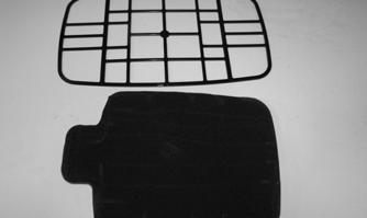
2.Remove the seat and tool tray; then disconnect the battery. 3.Remove the storage compartment cover and storage compartment. Remove the air filter housing cover; then remove the air filter. Account for the air filter frame.
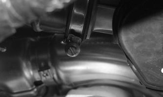
4.Loosen the clamps securing the intake pipe which joins the air box to the throttle body boots; then remove the pipe.
! WARNING
Do not turn the ignition switch to the ON position with the hoses removed and the battery connected. Gasoline will be pumped by the electric fuel pump causing a safety hazard.
CF687A
CF688
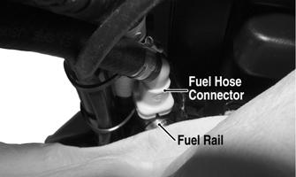
5.Slowly disconnect the fuel hose connector from the fuel rail.
! WARNING
Gasoline may be under pressure. Place an absorbent towel under the connector to absorb any gasoline spray when disconnecting.
CF691B
6.Remove the screw securing the throttle actuator cover to the throttle body; then remove the cover. 7.Remove the throttle cable from the actuator arm.
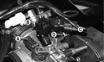
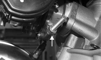
8.Loosen the outer jam nut securing the throttle cable to the throttle body; then route the cable out of the way. 9.Remove the MAP sensor (A), fuel injector connector (B), ISC connector (C), and TPS connector (D).
HDX136A
10.Loosen the clamp securing the throttle body to the intake manifold flange. Remove the throttle body.
CF684A
11.Remove the cap screws securing the intake manifold flange to the cylinder head. Account for an O-ring. 12.Use tape to cover and seal the intake opening.
CAUTION
Any objects or liquid entering the intake opening will fall into the engine causing severe damage if the engine is turned over or started.
INSTALLING 1.Place a new O-ring in the intake pipe; then position the pipe onto the engine and secure with two cap screws.
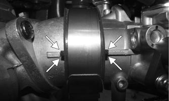
2.Using the alignment markings, install the intake pipe boot then the throttle body. Tighten the clamp securely.
CF694A
3.Connect the throttle cable to the throttle body and adjust throttle cable free-play (see Throttle Cable
Free-Play); then connect the fuel hose. 4.Connect the four electrical connectors to the throttle body components. 5.Install the intake pipe that joins the air filter housing to the throttle body and secure with the clamps.
Install the air filter, air filter frame, and air filter cover. Install the storage compartment and storage compartment cover. 6.Connect the battery (positive cable first) and install the tool tray; then install the seat making sure it locks securely in place. NOTE: If the throttle body, ECM, TPS, or ISC are
replaced, the EFI system must be synchronized. Use the following procedure:
1.With the key off, depress the throttle lever to Wide
Open Throttle (WOT). 2.Place the ignition key in the ON position and wait for 10 seconds.
3.Release the throttle lever and wait an additional 10 seconds.
4.Turn the key to the OFF position and allow the gauge to shut off.
Throttle Cable Free-Play
To adjust the throttle cable free-play, follow this procedure:
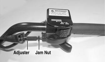
1.Slide the rubber boot away; then loosen the jam nut from the throttle cable adjuster.
CF297A
2.Turn the adjuster until the throttle cable has proper free-play of 3-6 mm (1/8-1/4 in.) at the lever.
3.Tighten the jam nut against the throttle cable adjuster securely; then slide the rubber boot over the adjuster.
Gas Tank
! WARNING
Whenever any maintenance or inspection is made on the fuel system during which there may be fuel leakage, there should be no welding, smoking, open flames, etc., in the area.
REMOVING (MudPro) 1.Remove the seat.
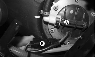
2.Remove the rear rack and fenders (see Steering/Body/Controls). 3.Using an absorbent towel under the hose, disconnect the fuel hose from the fuel pump by compressing the release on the connector (A). Disconnect the fuel gauge connector (B).
CF695A
4.Remove the cap screws securing the gas tank to the frame.
5.Remove the gas tank.
REMOVING (TBX) 1.Remove the seat and tilt the cargo box back; then remove the right-side plastic panel. 2.Set the shift lever to the Park position and apply the parking brake. Using a hydraulic jack, lift the right rear side of the frame to remove the right rear tire.
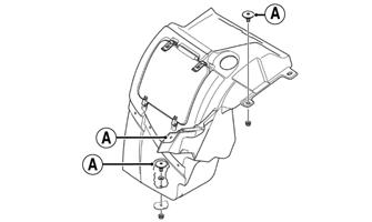
Place a support jack under the frame. 3.Remove the gas tank filler cap; then remove the fasteners securing the right-side footwell to the storage box assembly. Remove the fasteners (A) securing the storage box to the frame.
CF757A
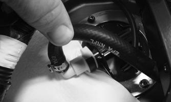
4.Disconnect the fuel pump main harness connector; then place a shop towel under the fuel hose connector at the fuel pump. Carefully rotate the connector to access the release tab. Disconnect the fuel hose connector from the fuel pump.
XR312
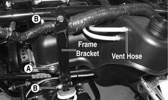
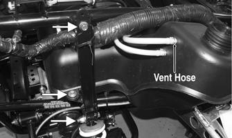
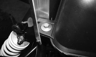
5.Remove the vent hose from the gas tank. Remove the fasteners (A) securing the gas tank to the right side frame bracket and to the left side of the frame. Support the right rear suspension assembly; then remove the frame bracket fasteners (B).
XR311B
XR313A
6.Remove the gas tank.
CLEANING AND INSPECTING 1.Clean all gas tank components with parts-cleaning solvent.
2.Inspect all hoses for cracks or leaks. 3.Inspect tank cap and tank for leaks, holes, and damaged threads. 4.Remove the fuel level sensor/fuel pick-up assembly and inspect the fuel level sensor and fuel screen. NOTE: If the fuel level sensor has failed or may be
faulty, see FUEL PUMP/FUEL LEVEL SENSOR in this section.
INSTALLING (MudPro) 1.Place the gas tank into position in the frame; then install the cap screws. Tighten securely. 2.Connect the fuel hose from the throttle body; then connect the fuel gauge connector. 3.Fill the gas tank with gasoline. 4.Start the engine and inspect for leakage. 5.Install the rear fenders and rack (see Steering/Body/Controls); then install the seat making sure it latches securely.
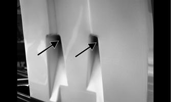
INSTALLING (TBX) 1.Install the gas tank into the frame and guide the front mounting tabs into the rubber grommets that are installed in the frame.
2.Lift the right rear shock into position; then secure the frame bracket to the frame. Secure the fasteners.
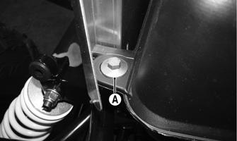
3.Align the gas tank to the frame bracket on the right and the frame on the left; then secure with the two cap screws. Using a new clamp, install the vent line to the gas tank. Tighten the upper shock mount to 50 ft-lb.
XR311A
XR313
4.Connect the fuel pump connector and fuel hose to the fuel pump. 5.Place the ride-side cargo box assembly into position and secure it to the frame and footwell.
6.Install the gas cap. 7.Install the right rear wheel: then using a crisscross pattern, tighten the lug nuts in 20 ft-lb increments to a final torque of 40 ft-lb (steel wheel), 60 ft-lb (aluminum wheel w/black nuts), or 80 ft-lb (aluminum wheel w/chrome nuts). 8.Install the right side panel and seat.
Oil Pressure
NOTE: Whenever internal engine components wear
excessively or break and whenever oil is contaminated, the oil pump should be replaced (see Engine/Transmission). The oil pump is not a serviceable component.
TESTING OIL PUMP PRESSURE NOTE: The engine must be warmed up to the speci-
fied temperature for this test.
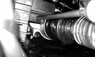
1.Connect the Tachometer to the engine or utilize the
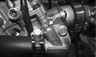
LCD (if equipped). 2.Connect the Oil Pressure Test Kit to the oil pressure test port.
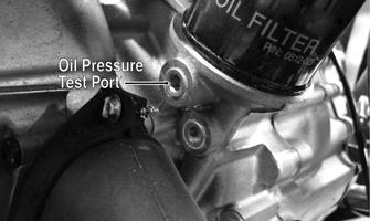
CF264C
NOTE: Some oil seepage may occur when installing
the oil pressure gauge. Wipe up oil residue with a cloth.
3.Start the engine and run at 3000 RPM. With the oil temperature at 60° C (140° F), the oil pressure gauge must read 1.2-1.5 kg/cm2 (17-21 psi). NOTE: If the oil pressure is lower than specified,
check for low oil level or defective oil pump.
NOTE: If the oil pressure is higher than specified,
check for too heavy engine oil weight (see General Information), clogged oil passage, clogged oil filter, or improper installation of the oil filter.
Oil Flow Chart
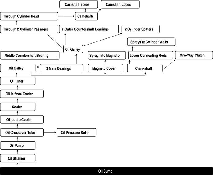
oil_flow_wt
Liquid Cooling System
When filling the cooling system, use a coolant/water mixture which will satisfy the coldest anticipated weather conditions of the area in accordance with the coolant manufacturer’s recommendations. While the cooling system is being filled, air pockets may develop; therefore, run the engine for five minutes after the initial fill, shut the engine off, and then fill the cooling system to the bottom of the stand pipe in the radiator neck.
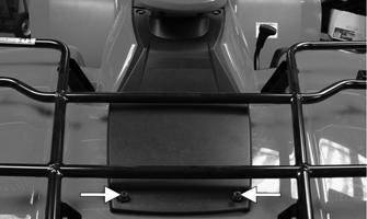
Checking/Filling 1.Remove the two screws from the front of the radiator access panel. ! WARNING
Never check the coolant level when the engine is hot or the cooling system is under pressure.

FI465A
2.Lift the front of the access panel; then slide the panel forward to disengage the two rear tabs. 3.Move the panel rearward until free of the rack. NOTE: Steps 4-6 are for the MudPro; for the TBX,
proceed to step 7.
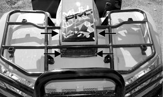
4.Remove four cap screws securing the snorkel housing to the front inspection panel; then remove two cap screws from the rear of the snorkel housing.
MP013A MP007A
5.Separate the front of the snorkel housing from the rear; then remove the snorkel housing.
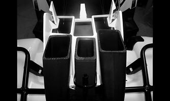
MP003
6.Remove two reinstallable rivets and remove the splash guard. The radiator cap can now be accessed in front of the snorkels.
7.Carefully rotate the radiator cap counterclockwise to release pressure; then remove the cap.
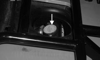
CF142A
8.Add coolant as necessary; then install the radiator cap, splash guard (if applicable), and access panel or snorkel housing. NOTE: Use a good quality, biodegradable gly-
col-based, automotive-type antifreeze.
CAUTION
After operating the ATV for the initial 5-10 minutes, stop the engine, allow the engine to cool down, and check the coolant level. Add coolant as necessary.
RADIATOR Removing 1.Drain the coolant by removing the drain screw found on the water pump. Account for the washer. Account for the crush washer.
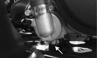
XR318A
NOTE: Removing the radiator cap will help evacu-
ate the majority of the coolant.
2.Remove the front rack (see Steering/Body/Controls). 3.Remove the front bumper and front fender panel (see
Steering/Body/Controls). 4.Remove the upper and lower coolant hoses. 5.Remove the cap screws and nuts securing the radiator to the frame.
6.Disconnect the fan wiring from the main wiring harness; then remove the radiator/fan assembly and account for the grommets and collars. 7.Remove the fan/fan shroud assembly from the radiator.
CC863
Cleaning and Inspecting 1.Flush the radiator with water to remove any contaminants.
2.Inspect the radiator for leaks and damage. 3.Inspect all hoses for cracks and deterioration. 4.Inspect all fasteners and grommets for damage or wear.
Installing 1.Position the fan/fan shroud assembly on the radiator; then secure with existing hardware. 2.Place the radiator with grommets and collars into position on the frame; then install the cap screws and nuts. Tighten securely. 3.Install the upper and lower coolant hoses; then secure with hose clamps.
AF734D
4.Install the front bumper and front fender panel (see
Steering/Frame/Controls). 5.Install the front rack (see Steering/Body/Controls). 6.Fill the cooling system with the recommended amount of antifreeze. Check for leakage. 7.Connect the fan wiring to the main wiring harness.
THERMOSTAT Removing 1.Drain approximately one quart of coolant from the cooling system. 2.Remove the two cap screws securing the thermostat housing to the cylinder head. Account for an O-ring and a thermostat.
Inspecting 1.Inspect the thermostat for corrosion or spring damage. 2.Using the following procedure, inspect the thermostat for proper operation:
A.Suspend the thermostat in a container filled with water.
B.Heat the water and monitor the temperature with a thermometer.
C.The thermostat should start to open at 146-151°F.
D.If the thermostat does not open, it must be replaced. 3.Inspect all coolant hoses, connections, and clamps for deterioration, cracks, and wear. NOTE: All coolant hoses and clamps should be
replaced every four years or 4000 miles.
Installing 1.Place the thermostat and O-ring into the thermostat housing; then secure the thermostat housing to the cylinder head with the two cap screws.
2.Fill the cooling system with the recommended amount of antifreeze (see Periodic Maintenance/Tune-Up). Check for leakage.
COOLING FAN Removing 1.Remove the radiator (see Radiator in this sub-section). 2.Remove the fan assembly from the radiator.
Installing 1.Position the fan assembly on the radiator; then secure with existing hardware. NOTE: The fan wiring must be in the upper-right
position.
2.Install the radiator.
WATER PUMP NOTE: The water pump is a non-serviceable com-
ponent. It must be replaced as an assembly.
Removing 1.Remove the radiator cap; then remove the water pump drain and drain the coolant.
XR318A
2.Drain the oil from the engine/transmission. 3.Remove the four Torx-head cap screws securing the front and rear fenders to the footrest; then remove the four cap screws securing the footrest to the frame.
Remove the footrest.
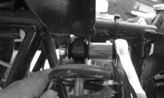
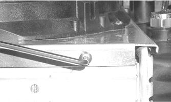
4.Loosen the hose clamps and slide the clamps away from the hose ends approximately 2 in.; then remove both hoses from the water pump. 5.Remove the two cap screws securing the water pump to the engine; then remove the water pump.
XR318B
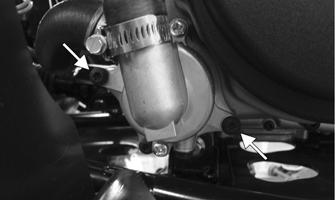
Installing 1.Secure the water pump to the engine with the two cap screws to 8.5 ft-lb.
2.Connect the two coolant hoses to the water pump and secure with the clamps. Tighten securely. 3.Place the footrest into position on the frame and loosely secure with four cap screws; then secure the front and rear fenders to the footrest with the four
Torx-head cap screws. Tighten the four Torx-head cap screws securely; then tighten the 8 mm cap screws to 20 ft-lb and the 10 mm cap screws to 40 ft-lb.
4.Fill the engine/transmission with the proper amount of recommended oil.
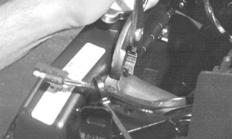
5.Loosen the bleed screw on the thermostat housing.
Fill the cooling system with the proper amount of recommended coolant until coolant seeps out from the bleed screw. Secure the bleed screw; then top off the radiator with coolant.
XR317A
NOTE: While the cooling system is being filled, air
pockets may develop; therefore, run the engine for five minutes after the initial fill, shut the engine off, and then fill the cooling system.
6.Check the entire cooling system for leakage.
CAUTION
After operating the ATV for the initial 5-10 minutes, stop the engine, allow the engine to cool down, and check the coolant level. Add coolant as necessary.
Troubleshooting
Problem: Starting impaired Condition Remedy
1. Gas contaminated 1.Drain gas tank and fill with clean gas
Problem: Idling or low speed impaired Condition Remedy
1. TPS out of adjustment 1.Adjust TPS
Problem: Medium or high speed impaired Condition Remedy
1. High RPM “cut out” against RPM limiter 1.Decrease RPM speed