17 minute read
Steering and Body

Steering Post
REMOVING NOTE: Perform steps 1-8 for both the brake and
throttle cables.
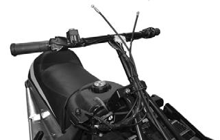
1.Remove the handlebar pad. 2.Remove the C-clips securing the brake and throttle lever pins in the brake housing and throttle control; then remove the pins and levers.
ZR-108
4.Remove the C-clip securing the throttle cable in the throttle control; then remove the cable from the throttle control.

ZR-105 ZR-109

5.Cut the cable ties securing the cables to the steering post.
ZR-106
3.Disconnect the brake and throttle cables from the levers; then slide the cables out of the levers.

ZR-110
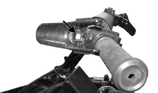
6.Using a sharp knife, cut the grip off the handlebar. 7.Using a solvent, clean the old adhesive from the handlebar.
8.Loosen the screw securing the emergency stop switch to the handlebar; then remove the stop switch. 9.Remove the two cap screws and lock nuts securing the upper steering post bearing retainer and supports; then remove the retainer and bearing.
ZR-111
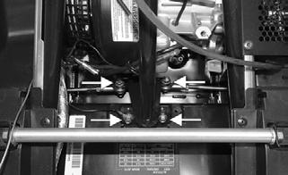
10.Remove the lock nuts and cap screws securing the tie rods to the steering post; then remove the cap screws and lock nuts securing the steering post to the chassis. Account for a washer, bearings, and the steering support bracket.

ZR-112
NOTE: Use an additional wrench to keep the tie rod
end shaft from turning while removing the tie rod lock nut.
11.Remove the steering post from the engine compartment.
INSPECTING 1.Inspect all welded areas for cracks or deterioration. 2.Inspect the steering post and bearing retainers for cracks, bends, or wear. 3.Inspect the steering post bearings for wear, cracks, or deterioration.
4.Inspect the tie rod ends for wear or damage.
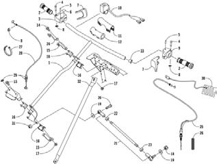
KEY 1.Steering Post 2.Handlebar Grip 3.Throttle Control 4.Pin 5.Spring Pin 6.Decal 7.Throttle/Brake Lever 8.Retaining Ring 9.Brake Housing 10.Engine Stop Switch 11.Pad Cover 12.Pad 13.Cap Screw 14.Cap Screw 15.Bearing Retainer 16.Bearing 17.Lock Nut 18.Lock Nut 19.Washer 20.Cap Screw 21.Tie Rod
Assembly 22.Hex Nut 23.Hex Nut 24.Harness Guide 25.Brake Cable 26.Spring 27.Cable Tie 28.Throttle Cable 29.Washer 30.Element 31.Hex Nut 32.Steering Support 33.Plug
SNO-977
1.Place the lower steering post bearings and retainer into position on the lower portion of the steering post; then place the steering post into position and loosely secure with cap screws, washer, trainer, and lock nuts.
2.Secure the inner tie rods to the steering post with washers and lock nuts (coated with green Loctite #609). Tighten to 20 ft-lb.
ZR-112
NOTE: Use an additional wrench to keep the tie rod
end shaft from turning while tightening the tie rod lock nut.
3.Place the upper steering post bearings into position on the steering post and secure the steering post/ bearing assembly to the support with the bearing retainer, cap screws, harness guide, supports, and lock nuts.
ZR-111
NOTE: Check all fasteners to ensure they are tight.
Turn the handlebar full-left and full-right several times to ensure free movement.
5.Apply Handlebar Adhesive to the bore of the handlebar grip; then using a rubber hammer, drive the grip into position.
6.Place the emergency stop switch onto the right handlebar and secure with the screw.
7.Route the throttle cable through the slot in the throttle control and insert the cable end into the throttle control. Secure the cable with a C-clip.
! WARNING
The handlebar adhesive is extremely flammable. This product contains acetone. The vapors released can be easily ignited. Keep away from heat, sparks, and open flame. Use only in a well ventilated area. Avoid prolonged breathing of vapor. Avoid eye and skin contact. Keep container closed when not in use.
ZR-107
ZR-108
ZR-106
ZR-109
8.Seat each cable drum into its lever recess; then secure each with a pin and C-clip.
ZR-105
The ski wear bar is a replaceable bar attached to the underside of the ski. The purpose of the wear bar is to assist in turning the snowmobile, to minimize ski wear, and to maintain good steering control. If the snowmobile is operated primarily in deep snow, ski wear bar wear will be minimal; however, if the snowmobile is operated on terrain where the snow cover is minimal, the ski wear bar will wear faster. Arctic Cat recommends that the ski wear bars be checked once a week and replaced if worn to 1/2 of original diameter.
REMOVING 1.Using a suitable stand or lift, raise the front of the snowmobile off the floor; then remove the lock nuts securing the wear bar to the ski. 2.Pry the rear of the wear bar down until the wear bar studs are clear of the ski; then slide the wear bar rearward until the front of the wear bar is free from the ski.
3.Remove the wear bar.
INSTALLING 1.Insert the front of the wear bar into the hole at the front of the ski and swing the wear bar upward; then insert the wear bar studs into the holes in the ski.
2.Center the wear bar studs in the holes and install the lock nuts. Tighten lock nuts securely.
! WARNING
DO NOT bend the ski wear bar excessively when installing. Excessive bending of the ski wear bar may cause premature wear, breakage, and possible injury.
Ski
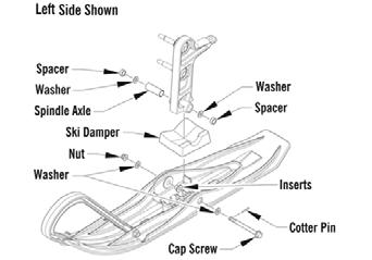
REMOVING 1.Elevate the front of the snowmobile and secure on a support stand. 2.Remove and discard the cotter pin; then remove the nut and cap screw securing the ski to the spindle. NOTE: Note the orientation of the damper for
installation purposes.
3.Remove the ski. Account for the rubber damper, spacers, and washers.
INSPECTING 1.Inspect the ski for cracks or deterioration. 2.Inspect the ski for abnormal bends or cracks. 3.Inspect the wear bar for wear. 4.Inspect all hardware and the spindle bushings for wear and damage. 5.Inspect the rubber damper for damage or wear.
INSTALLING 1.Slide a washer onto the cap screw used to secure the ski; then apply a low-temperature grease to the shaft portion of the cap screw and spindle axle. 2.Install the spindle axle into the spindle; then position the washers on the outside of the spindle and the spacers on the outside of the washers. Position the ski damper under the spindle.
0750-989
NOTE: The ski damper must be positioned in the
ski so it is directly under the spindle.
NOTE: The ski stance can be adjusted by moving
the spacers and the ski damper to either side of the spindle.
3.With the cap screw hole of the ski centered with the spindle axle, slide the cap screw with washer through the outside of the ski and spindle assemblies. NOTE: Install the cap screw so the lock nut will be
located to the inside of the ski and the cotter pin slot in the cap screw will be horizontal with the ski.
4.Install the remaining washer and lock nut; then tighten the lock nut to 16 ft-lb. NOTE: Ensure that the cotter pin slot in the cap
screw is still horizontal with the ski.
5.Install a new cotter pin from the back side of the ski cap screw and spread the pin.
Tie Rods
NOTE: The tie rod boot does not need to be
removed for this procedure.
REMOVING AND DISASSEMBLING 1.Remove the tie rod from the spindle.
ZR-116
2.Open the hood; then remove the tie rod from the steering post.
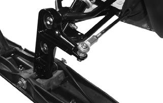
ZR-117
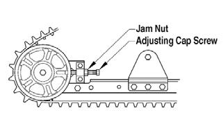
3.Slide the tie rod from the steering boot. Loosen the jam nuts securing the tie rod; then remove the ball joints from the tie rod.
CLEANING AND INSPECTING 1.Inspect the ball joints and tie rods for damaged threads or wear.
2.Inspect the ball joints and tie rods for cracks or unusual bends.

3.Wash the ball joint in parts-cleaning solvent. Dry with compressed air. Inspect the ball joint pivot area for wear. Apply an all-temperature grease to the ball joint.
! WARNING
Always wear safety glasses when using compressed air.
ASSEMBLING AND INSTALLING 1.Install the jam nuts and thread the ball joints onto the tie rod; then slide the tie rod through the steering boot.
NOTE: Each jam nut and ball joint is either a right-
hand or left-hand thread; therefore, each can only be installed on one end of the tie rod. The right-hand thread is the inside ball joint and jam nut.
2.Secure the inner tie rod to the steering post with washers and new lock nuts. Tighten to 20 ft-lb. 3.Secure the outer tie rod to the spindle with a washer and new lock nut (coated with blue Loctite #243).
Tighten to 15 ft-lb.
ZR-116
4.Lock the jam nuts against the tie rod; then adjust ski alignment (see Ski Alignment sub-section). ! WARNING
Neglecting to lock the jam nuts against the tie rod may cause loss of snowmobile control and possible personal injury.
Spindle
REMOVING 1.Position the front of the snowmobile up onto a safety stand.
2.Remove the ski.
3.Remove the lock nut securing the tie-rod ball joint to the spindle (account for the washer); then remove the ball joint from the spindle.
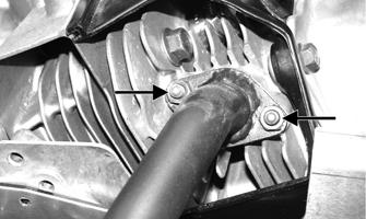
4.Remove the two lock nuts securing the spindle to the
A-arms.
SNO-980A
5.Inspect the tie-rod ball joint in place. If damage, wear, or unusual bends are noted, loosen the jam nut; then remove the ball joint from the tie rod.
INSPECTING 1.Inspect the spindle for excessive wear, cracks, bends, or imperfections. NOTE: The spindle should not be disassembled. It
will only be sold as an assembly.
INSTALLING 1.Install the spindle assembly into the upper and lower
A-arms and secure using two new lock nuts. Tighten (head-side) to 20 ft-lb.
SNO-980A
2.Place the tie-rod ball joint into position on the bottom side of the spindle arm and secure with a lock nut (threads coated with blue Loctite #243) tightened to 15 ft-lb.
3.Install the ski.
4.Remove the safety stand from beneath the front frame assembly.
Ski Alignment
CHECKING 1.Turn the handlebar to the straight-ahead position. 2.Measure the distances to the inside edges of the skis in two places. Make sure the measurements are taken behind the spindle mount and ahead of the spindle mount.
ADJUSTING 1.Make sure the ignition key is in the OFF position. 2.Visually examine the skis to determine which ski is out of alignment with respect to the handlebar. 3.Open the hood and loosen the jam nut on each end of the tie rod.
4.While holding the straight ski in position, rotate the tie rod until the measurement between the skis is within specifications. 5.When the ski alignment is correct, apply blue Loctite #243 to the jam nut threaded areas and tighten each jam nut securely against the tie rod.
! WARNING
Neglecting to lock the tie rod by tightening the jam nuts may cause loss of snowmobile control and possible personal injury.
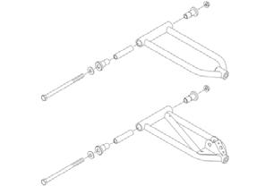
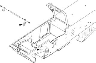
Front Suspension A-Arms
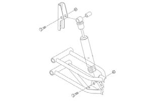
REMOVING 1.Position the front of the snowmobile up onto a safety stand; then remove the two nuts securing the spindle to the A-arms. Remove the spindle and ski as an assembly.
SNO-980
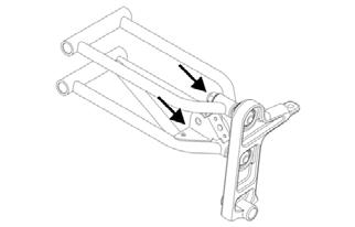
2.Remove the cap screws and lock nuts securing the shock chassis bracket and the lower A-arm; then remove the shock. Account for the upper shock bushing.
0735-446
NOTE: Ski alignment is correct when the skis are
parallel to each other (equal measurements front and rear) or when the skis have up to a maximum of 1/4” toe out (front measurement 1/4” more than rear measurement).
3.If ski alignment is not as specified, the snowmobile will have a tendency to wander and may be difficult to control; therefore, an adjustment is necessary.
SNO-979
3.Remove the rivets securing the tie-rod boots to the chassis making sure not to drill into the boots; then slide the boots off the tie-rods.
SNO-981
4.Remove the rivets securing the front of the belly pan to the chassis; then remove the rivets securing the belly panel to the chassis around the A-arms.
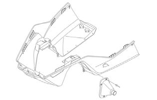

SNO-982
5.Remove the lock nuts securing the A-arms to the chassis; then push the cap screws and washers as far forward as possible. Remove the A-arms and account for two outer axles and an inner axle for each arm.
SNO-983
INSPECTING 1.Inspect the A-arm welded areas for cracks or any signs of deterioration. 2.Inspect the axles for wear or damage. 3.Inspect the tubing for signs of being twisted or bent.
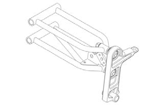
KEY 1.Upper A-Arm 2.Lower A-Arm 3.Washer 4.Axle 5.Axle 6.Cap Screw 7.Lock Nut
SNO-984
1.Install the inner and outer axles into the upper and lower A-arms; then position the arms with the mounting locations in the chassis; then secure with the existing cap screws, washers, and new lock nuts.
Tighten to 30 ft-lb. NOTE: If replacing both the right- and left-side A-
arms, do not rivet the belly pan to the chassis until all arms are replaced.
2.Install the upper shock bracket to the chassis using the existing cap screws and nuts. Tighten to 20 ft-lb. 3.Secure the idler axle to the shock brackets using the existing cap screws and washers. Tighten to 20 ft-lb.
SNO-985
4.Secure the belly pan to the chassis using new rivets; then secure the tie-rod boots to the chassis using new rivets.
SNO-982
5.Install the shock to the shock bracket and the lower
A-arm using the existing upper axle, cap screws, and new lock nuts. Tighten to 16 ft-lb. 6.Install the spindle and ski assembly to the A-arms and secure using new lock nuts. Tighten to 20 ft-lb (torque head-side).
Belly Pan
REMOVING 1.Remove the hood.
2.Remove the two screws securing the belly pan to the front end.
3.Remove the two Phillips-head screws securing the belly pan to the footrest supports. NOTE: Always tip the snowmobile onto the left side
to avoid oil from draining into the air intake.
4.Using a piece of cardboard to protect the finish, tip the snowmobile onto the left side and using a #20 drill bit, drill out the belly pan rivets.

SNO-986
NOTE: The tie rod boots do not need to be removed.
5.With all belly pan rivets removed, return the snowmobile to the upright position; then slide the belly pan forward and up until it clears the front end.
INSPECTING 1.Inspect for gouges, cuts, and tears. 2.Inspect the two belly pan threaded bosses and ensure they are in good shape.
INSTALLING 1.Slide the belly pan into position on the front end; then secure with the existing screws. 2.Install the belly pan rivets in each ski-well. 3.Using a piece of cardboard to protect the finish, tip the snowmobile onto the left side and install the remaining belly pan rivets; then return the snowmobile to the upright position. 4.Install the hood.
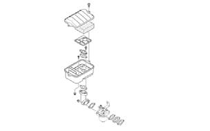
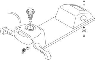
Seat/Cushion/Taillight Housing
KEY 1. Seat Assy 2. Gas Tank/Seat-Base 3. Cap w/Gauge 4. Seal 5. Seat Cover 6. Seat Wire 7. Foam 8. Seat Wire 9. Staple 10. Clip 11. Vent Hose 12. Bushing 13. Push Nut 14. Decal 15. Teflon Tape 16. Shut-Off Valve 17. Hose Clamp 18. Fuel Hose 19. Fuel Filter 20. Hose Clamp 21. Fuel Hose 22. Hose Clamp 23. Cable Tie 24. Spring 25. Choke Cable 26. Nut 27. Decal 28. Ignition Switch 29. Retaining Nut 30. Ignition Switch Key 31. Cap Screw 32. Lock Nut 33. Washer 34. Cap Nut 35. Taillight Assy 36. Washer 37. Nut w/Washer
0747-299
REMOVING 1.Remove the retaining nut securing the ignition switch to the console; then slide the switch forward and out of the console.
2.Remove the screw securing the choke knob to the cable; then remove the knob. 3.Remove the two nuts securing the choke cable to the console; then slide the cable forward and out of the console.
4.Pull the recoil starter rope out approximately 24"; then tie a slip-knot in the starter rope below the console and allow the rope to slowly retract against the starter case.
5.Remove the knot at the handle and remove the handle; then thread the rope through the bushing in the console.
6.Turn the gas tank shut-off valve to the CLOSED position; then disconnect the fuel hose from the carburetor.
7.Remove the vent hose from the top of the gas tank.
! WARNING
Whenever any maintenance or inspection is made on a fuel system when there may be fuel leakage, there should be no welding, smoking, open flames, etc., in the area.
SNO-987
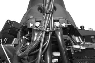
8.Raise the flap at the rear of the seat and remove the two cap nuts securing the seat assembly to the tunnel. Account for two washers.
9.Raise the rear of the seat assembly high enough to disconnect the taillight wiring harness; then disconnect the taillight from the main wiring harness. 10.Remove the seat assembly. NOTE: If necessary, use a sharp tool to pry out all
staples securing the seat cover to the plastic seat base; then remove the cover from the seat base and seat foam.
INSTALLING NOTE: If the seat cover was removed, position the
cover over the seat foam and plastic seat base. Check to make sure it is positioned straight; then fold the rear edge of the cushion down and around the base. Using a staple gun and 1/4-in. staples, staple the rear flap of the cushion to the base in the same areas as the original staples were located. Position staples 1" apart. Fold the sides of the cushion down around the bottom edge of the base. Position the staples in the same areas as the original staples were located.
1.Place the seat assembly into position and connect the taillight wiring harness. 2.Secure the seat assembly to the tunnel with washers and cap nuts. 3.Connect the vent hose to the top of the gas tank. 4.Thread the recoil starter rope through the bushing in the console and the handle; then tie a knot at the end of the rope and pull the handle up and onto the knot. 5.Untie the slip-knot at the starter case and allow it to slowly rewind into the case. 6.Slide the choke cable through the console and secure with two lock nuts; then using a screw (coated with blue Loctite #243), secure the choke knob to the end of the cable. 7.Slide the ignition switch into position on the console; then secure with the retaining nut. 8.Connect the fuel hose to the carburetor and turn the gas tank shut-off valve to the OPEN position.
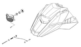
Headlight Assembly
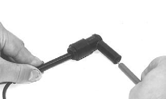
REMOVING NOTE: The bulb portion of the headlight is fragile.
HANDLE WITH CARE. When replacing the headlight bulb, the bulb assembly must first be removed from the housing. Do not touch the glass portion of the bulb. If the glass is touched, it must be cleaned with a dry cloth before installing.
1.Disconnect the harness from the back of the bulb; then remove the rubber boot.
2.Rotate the spring retainer securing the bulb in the headlight; then carefully remove the bulb. 3.Remove the two pins securing the outer portion of the headlight; then remove the screw securing the lower portion of the headlight. Remove the headlight from the hood.
SNO-988
INSTALLING 1.Install the headlight assembly into the hood tabs and secure using the existing pins and screw. NOTE: The hood cable is secured with the lower
adjustment screw.
2.Insert the headlight bulb into the headlight assembly; then install the spring retainer. Install the rubber boot and connect the harness to the bulb.
NOTE: To adjust headlight aim, adjust the adjust-