15 minute read
Electrical System

The electrical connections should be checked periodically for proper function. In case of an electrical failure, check fuse, connections (for tightness, corrosion, damage), and/or bulb. Each time the ATV is used, switches should be checked for proper operation. Use the following list for reference: A.Ignition switch — engine will start (with brake lever compressed). B.Emergency stop switch — engine will stop. C.Brake light switch — brake light will illuminate with brake lever(s) compressed.
Testing Electrical Components All of the electrical tests should be made using the Fluke Model 77 Multimeter. If any other type of meter is used, readings may vary due to internal circuitry. When troubleshooting a specific component, always verify first the fuse is good, the bulb is good, the connections are clean and tight, the battery is fully charged, and all appropriate switches are activated.
NOTE: For absolute accuracy, all tests should be
made at room temperature (approximately 68° F).
Battery
The battery is located under the seat. After being in service, batteries require regular cleaning and recharging in order to deliver peak performance and maximum service life. The following procedure is recommended for cleaning and maintaining a sealed battery. Always read and follow instructions provided with battery chargers and battery products. NOTE: Refer to all warnings and cautions provided
with the battery or battery maintainer/charger.
Loss of battery charge may be caused by ambient temperature, ignition OFF current draw, corroded terminals, self discharge, frequent start/stops, and short engine run times. Extended low RPM operation, short trips, and high amperage accessory usage are also reasons for battery discharge.
Maintenance Charging NOTE: Use the CTEK Multi US 800 or the CTEK
Multi US 3300 for battery maintenance charging. Maintenance charging is required on all batteries not used for more than two weeks or as required by battery drain.
800A
1.When charging a battery in the vehicle, be sure the ignition switch is in the OFF position. 2.Clean the battery terminals with a solution of baking soda and water.
NOTE: The sealing strip should NOT be removed
and NO fluid should be added.
3.Be sure the charger and battery are in a well-ventilated area. Be sure the charger is unplugged from the 110-volt electrical outlet.
4.Connect the red terminal lead from the charger to the positive terminal of the battery; then connect the black terminal lead of the charger to the negative terminal of the battery. NOTE: Optional battery charging adapters are
available from your authorized dealer to connect directly to your vehicle from the recommended chargers to simplify the maintenance charging process. Check with your authorized dealer for proper installation of these charging adapter connectors.
5.Plug the battery charger into a 110-volt electrical outlet.
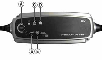
6.If using the CTEK Multi US 800, there are no further buttons to push. If using the CTEK Multi US 3300, press the Mode button (A) at the left of the charger until the Maintenance Charge Icon (B) at the bottom illuminates. The Normal Charge Indicator (C) should illuminate on the upper portion of the battery charger. NOTE: The maintainer/charger will charge the bat-
tery to 95% capacity at which time the Maintenance Charge Indicator (D) will illuminate and the maintainer/charger will change to pulse/float maintenance. If the battery falls below 12.9 DC volts, the charger will automatically start again at the first step of the charge sequence.
3300C
NOTE: Not using a battery charger with the proper
float maintenance will damage the battery if connected over extended periods.
Charging NOTE: Use the CTEK Multi US 800 or the CTEK
Multi US 3300 for battery maintenance charging.
1.Be sure the battery and terminals have been cleaned with a baking soda and water solution. NOTE: The sealing strip should NOT be removed
and NO fluid should be added.
2.Be sure the charger and battery are in a well-ventilated area. Be sure the charger is unplugged from the 110-volt electrical outlet.
3.Connect the red terminal lead from the charger to the positive terminal of the battery; then connect the black terminal lead of the charger to the negative terminal of the battery. 4.Plug the charger into a 110-volt electrical outlet. 5.By pushing the Mode button (A) on the left side of the charger, select the Normal Charge Icon (E). The
Normal Charge Indicator (C) should illuminate on the upper left portion of the charger. 6.The battery will charge to 95% of its capacity at which time the Maintenance Charge Indicator (D) will illuminate.
NOTE: For optimal charge and performance, leave
the charger connected to the battery for a minimum 1 hour after the Maintenance Charge Indicator (D) illuminates. If the battery becomes hot to the touch, stop charging. Resume after it has cooled.
7.Once the battery has reached full charge, unplug the charger from the 110-volt electrical outlet. NOTE: If, after charging, the battery does not per-
form to operator expectations, bring the battery to an authorized dealer for further troubleshooting.
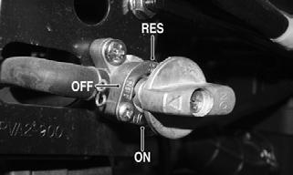
Ignition Switch
The connector is accessible below the front fender panel in front of the steering post.
VOLTAGE NOTE: Perform this test on the harness side of the
connector.
1.Set the meter selector to the DC Voltage position. 2.Connect the red meter lead to the red wire; then connect the black meter lead to a suitable ground. 3.Meter must read battery voltage. NOTE: If the meter reads no battery voltage, trou-
bleshoot the battery, fuse, or the main wiring harness.
RESISTANCE
CAUTION
Always disconnect the battery when performing resistance tests to avoid damaging the multimeter.
NOTE: Perform this test on the switch side of the
connector.
1.Turn the ignition switch to the ON position. 2.Set the meter selector to the OHMS position. 3.Connect the red tester lead to the red wire; then connect the black tester lead to the black wire.
4.The meter must read less than 1 ohm.
5.With the switch in the OFF position, connect the red tester lead to the green wire and the black tester lead to the black/white wire. The meter must read an open circuit on both wires.
NOTE: If the meter reads more than 1 ohm of resis-
tance, troubleshoot or replace the switch/ component, the connector, or the switch wiring harness.
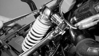
Ignition Coil
The ignition coil is attached to the frame above the front right shock absorber.
CAUTION
Always disconnect the battery when performing resistance tests to avoid damaging the multimeter.
NOTE: For these tests, the meter selector should be
set to the OHMS position.
PRIMARY WINDING RESISTANCE 1.Disconnect the black/yellow and green wires from the coil.
2.Connect the red tester lead to one terminal; then connect the black tester lead to the other terminal.
3.The meter must read less than 1 ohm.
NOTE: If the meter does not read as specified,
replace ignition coil.
PRIMARY VOLTAGE 1.Set the meter to DCV. Disconnect the black/yellow wire and green wire from the ignition coil; then turn the ignition switch to the ON position.
2.Connect the black meter lead to the black/yellow wire and the red meter lead to the green wire. 3.The reading must show approximately battery voltage.
SECONDARY WINDING RESISTANCE 1.Remove both primary wires. 2.Connect the red tester lead to the high tension lead (plug cap removed); then connect the black tester lead to either primary lead. 3.The meter must read 2830-3170 ohms.
NOTE: If the meter does not read as specified,
replace the ignition coil.
SECONDARY VOLTAGE 1.Remove the spark plug cap from the spark plug. 2.Connect the spark plug cap to Ignition Test Plug or other suitable tool; then ground the tool away from the spark plug hole. While turning the engine over, check for sufficient spark.
SPARK PLUG CAP RESISTANCE 1.Connect the red tester lead to one end of the cap; then connect the black tester lead to the other end of the cap. 2.The meter must read 4725-5775 ohms.
NOTE: If the meter does not read as specified,
replace the spark plug cap.
Ignition Timing
The ignition timing cannot be adjusted; however, verifying ignition timing can aid in troubleshooting other components. To verify ignition timing, use the following procedure: 1.Attach the Timing Light (p/n 0644-296) to the spark plug high tension lead; then remove the right footwell and the right-side fan cover. 2.Using the Tachometer (p/n 0644-275), start the engine and run at 1800 RPM; ignition timing should be 13° BTDC (“F” mark). 3.Install the fan cover and right footwell. If ignition timing cannot be verified, the rotor may be damaged, the key may be sheared, the trigger coil bracket may be bent or damaged, or the CDI unit may be faulty.
Handlebar Control Switches
The connector is in front of the steering post. The connector is accessible beneath the front fender. CAUTION
Always disconnect the battery when performing resistance tests to avoid damaging the multimeter.
RESISTANCE (Starter Button) 1.Set the meter selector to the OHMS position. 2.Connect the red tester lead to the yellow/red wire; then connect the black tester lead to the green wire. 3.With the starter button depressed, the meter must read less than 1 ohm.
4.With the starter button released, the meter must read an open circuit. NOTE: If the meter does not read as specified,
replace the switch/component, connector, or switch harness.
RESISTANCE (Emergency Stop) 1.Set the meter selector to the OHMS position. 2.Connect the red tester lead to the blue/yellow wire; then connect the black tester lead to the green wire. 3.With the switch in the OFF position, the meter must read an open circuit. 4.With the switch in the RUN position, the meter must read less than 1 ohm.
NOTE: If the meter reads more than 1 ohm of resis-
tance, troubleshoot or replace the switch/component, the connector, or the switch wiring harness.
Brake Light Switches
The left brake switch can be tested at the handlebar. The right brake switch connector is located under the right front fender.
NOTE: The ignition switch must be in the ON posi-
tion.
VOLTAGE (Wiring Harness Connector) 1.Set the meter selector to the DC Voltage position; then turn the ignition switch to the ON position. 2.Connect the red tester lead to the black wire; then connect the black tester lead to a suitable ground. 3.The meter must read battery voltage. NOTE: If the meter reads no battery voltage, trou-
bleshoot the battery, fuse, switch, or the main wiring harness.
NOTE: If the meter reads battery voltage, the main
wiring harness is good; test the switch/component, the connector, and the switch wiring harness for resistance.
CAUTION
Always disconnect the battery when performing resistance tests to avoid damaging the multimeter.
NOTE: The brake lever must be compressed for this
test. Also, the ignition switch must be in the OFF position. Disconnect the switches.
1.Set the meter selector to the OHMS position. 2.Connect the red tester lead to the black wire; then connect the black tester lead to the green/yellow wire.
3.When the lever is compressed, the meter must read less than 1 ohm.
NOTE: If the meter reads more than 1 ohm of resis-
tance, troubleshoot or replace the switch/component, the connector, or the switch wiring harness.
Headlights
The two-pin white connectors are located under the front fender assembly.
BULB VERIFICATION Visually inspect the bulb for broken filaments, blackening, or loose bulb base.
VOLTAGE NOTE: Perform this test on the main harness side of
the connectors. The engine must be running for this test.
1.Set the meter to the AC Voltage position. 2.Connect the black tester lead to one side of the connector and the red tester lead to the other side.
3.With the engine running, the meter must show 9.013.5 AC volts.
NOTE: If the meter shows no voltage, inspect wir-
ing harness or connectors. If normal, perform a stator coil test.
NOTE: The resistor is mounted to the frame on the
left side of the vehicle above the CVT housing.
LIGHTING RELAY RESISTOR 1.Set the meter to Ohms.
2.Disconnect the resistor from the main harness.
3.Place the red meter lead to the green/black wire and the black meter lead to a suitable ground. 4.The meter should read approximately 10.2 ohms. Disconnect the three-wire connector in front of the steering post; then insert a jumper wire to connect the timing sensor to the harness (blue/yellow wire).
VOLTAGE (No Load) 1.Set the meter selector to the AC Voltage position. 2.Connect the red tester lead to the white wire; then connect the black tester lead to a suitable ground. 3.With the transmission in neutral, start the engine and run at 3000 RPM or to the RPM limiter. The meter must read 13.5-16.5 AC volts.
RESISTANCE 1.Set the meter selector to the OHMS position. 2.Connect the red tester lead to the yellow wire; then connect the black tester lead to a suitable ground. 3.The meter must read less than 1 ohm.
4.Move the red test lead to the white wire. The meter must read approximately 1 ohm.
Regulator/Rectifier
The regulator/rectifier is located near the front left top shock mount.
VOLTAGE 1.Set the meter selector to the DC Voltage position. 2.Connect the red tester lead to the red wire and the black tester lead to the green wire (with the regulator/rectifier plugged in). 3.With the engine running at a constant 3000 RPM, the meter must read 12.1-15.2 DC volts.
Timing Sensor
Disconnect the three-wire connector next to the steering post.
VOLTAGE Set the meter to VAC. Connect the timing sensor connector; then connect the red tester lead to the blue/yellow wire and the black tester lead to a suitable ground. At idle, the meter will read approximately 0.35 VAC and should increase up to 0.7 VAC as RPMs are increased.
RESISTANCE 1.Set the meter selector to the OHMS position. 2.Connect the red tester lead to the blue/yellow wire; then connect the black tester lead to a suitable ground. 3.The meter must read 80-160 ohms.
NOTE: The starter motor is not a serviceable component. If the motor is defective, it must be replaced.
REMOVING 1.Disconnect the battery.
2.Remove the starter motor from the engine (see
Engine/Transmission). 3.Remove the nut securing the positive cable to the starter; then remove the cable from the starter.
Account for an O-ring.
CAUTION
Always disconnect the negative battery cable from the battery first; then disconnect the positive cable.
INSTALLING Install the starter motor (see Engine/Transmission).
Choke Circuit
Disconnect the white two-pin connector adjacent to the steering post.
VOLTAGE NOTE: The battery must be at full charge for this
test.
1.Set the meter selector to the AC Voltage position. 2.Connect the red tester lead to the yellow wire; then connect the black tester lead to the green/black wire. 3.Crank the engine over using the electric starter. The meter must read 3.5-4.5 AC volts.
Fuse
The main (7 amp) fuse is located on the frame near the battery under the seat. NOTE: To remove the fuse, separate the fuse case
and lift out.
If there is any type of electrical system failure, always check the fuse first.
1.Set the meter selector to the OHMS position. 2.Connect the red tester lead to one end of the fuse; then connect the black tester lead to the other end.
3.The meter must read less than 1 ohm resistance. If the meter reads open, replace the fuse.
CAUTION
Always replace a blown fuse with a fuse of the same type and rating.
CAUTION
Always disconnect the battery when performing resistance tests to avoid damaging the multimeter.
NOTE: Make sure the fuse is returned to its proper
position according to amperage.
Troubleshooting
Problem: Spark absent or weak Condition Remedy
1. Ignition coil defective 1.Replace ignition coil 2. Spark plug defective 2.Replace plug 3. Magneto defective 3.Replace magneto 4. CDI unit defective 4.Replace CDI unit
Problem: Spark plug fouled with carbon Condition Remedy
1. Idle RPM too high 1.Adjust carburetor 2. Gasoline incorrect 2.Change to correct gasoline 3. Air filter element dirty 3.Clean element 4. Spark plug incorrect (too cold) 4.Replace plug with proper heat range
Problem: Spark plug electrodes overheat or burn Condition Remedy
1. Spark plug incorrect (too hot) 1.Replace plug 2. Engine overheats 2.Check cooling fan air intake blockage — damage to fan — cooling shroud 3. Spark plug loose 3.Tighten plug
Problem: Magneto does not charge Condition Remedy
1. Lead wires — connections shorted — loose — open 1.Repair — replace — tighten lead wires 2. Magneto coils shorted — grounded — open 2.Replace magneto coils 3. Regulator/rectifier shorted — punctured 3.Replace regulator/rectifier
Problem: Magneto charges, but charging rate is below the specification Condition Remedy
1. Lead wires shorted — open — loose (at terminals) 1.Repair — tighten lead wires 2. Stator coils (magneto) grounded — open 2.Replace stator coils 3. Regulator/rectifier defective 3.Replace regulator/rectifier 4. Cell plates (battery) defective 4.Replace battery
Problem: Magneto overcharges Condition Remedy
1. Internal battery short circuited 1.Replace battery 2. Regulator/rectifier resistor damaged — defective 2.Replace resistor 3. Regulator/rectifier poorly grounded 3.Clean — tighten ground connection
Problem: Charging unstable Condition Remedy
1. Lead wire intermittently shorting 1.Replace lead wire 2. Magneto internally shorted 2.Replace magneto 3. Regulator/rectifier defective 3.Replace regulator/rectifier
Problem: Starter button not effective Condition Remedy
1. Battery charge low 1.Charge — replace battery 2. Switch contacts defective 2.Replace switch 3. Starter motor brushes not seating 3.Repair — replace brushes 4. Starter relay defective 4.Replace relay 5. Emergency stop — ignition switch off 5.Turn on switches 6. Wiring connections loose — disconnected 6.Connect — tighten — repair connections
Problem: Battery “sulfation” (Acidic white powdery substance or spots on surfaces of cell plates) Condition Remedy
1. Charging rate too low — too high 1.Replace battery 2. Specific gravity too high — too low 2.Charge battery 3. Battery run down — damaged 3.Replace battery 4. Electrolyte contaminated 4.Replace battery
Problem: Battery discharges too rapidly Condition Remedy
1. Electrolyte contaminated 1.Replace battery 2. Specific gravity too high 2.Charge battery 3. Charging system (charging operation) not set properly 3.Check magneto — regulator/rectifier — circuit connections — adjust for specified charging operation 4. Cell plates overcharged — damaged 4.Replace battery — correct charging system 5. Battery short circuited 5.Replace battery 6. Specific gravity too low 6.Charge battery 7. Electrolyte contaminated 7.Replace battery
Problem: Battery polarity reversed Condition Remedy
1. Battery incorrectly connected 1.Reverse connections — replace battery