8 minute read
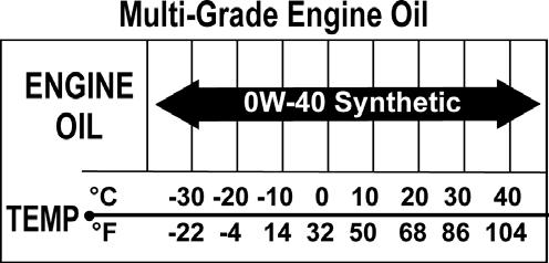
Fuel/Lubrication

This section has been organized for servicing the fuel system. The technician should use discretion and sound judgment when removing/disassembling and assembling/ installing components.
! WARNING
Whenever any maintenance or inspection is made on a fuel system when there may be fuel leakage, there should be no welding, smoking, open flames, etc., in the area.
Carburetor
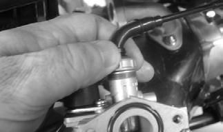
REMOVING 1.Turn the gas tank valve to the OFF position; then disconnect the gas hose from the carburetor.
CD590
2.Disconnect the float chamber drain hose and the vent hose from the carburetor.
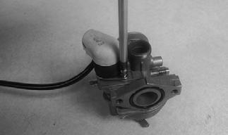
3.Loosen the air intake boot clamp.
YT260
4.Remove the cap screws securing the carburetor to the intake manifold; then remove the carburetor.
Account for the spacer and O-rings.
YT261A
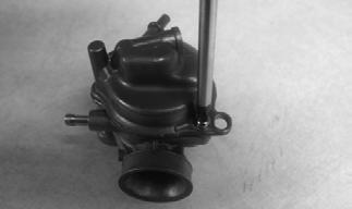
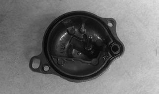
5.Unscrew the carburetor cap; then lift the cap removing the throttle valve, spring, and jet needle. Account for a gasket, a needle clip plate, and a needle clip.
CD594
6.Disconnect the choke assembly connector; then remove the carburetor.

YT222
DISASSEMBLING 1.Remove the two Phillips-head screws securing the choke assembly; then remove the assembly. Account for the washers and the O-ring. 2.Remove the Phillips-head screws securing the float chamber; then remove the chamber. Account for the seal and the washers.
CD600
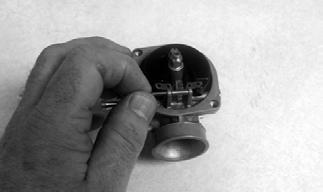
3.Remove the float pin; then lift the float with needle valve from the carburetor body.
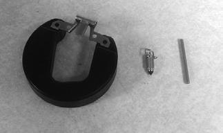
CD603
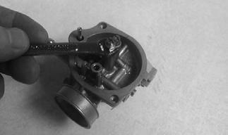
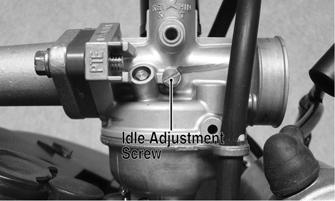
4.Remove the idle adjustment screw assembly.
Account for a spring.
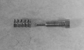
CD610
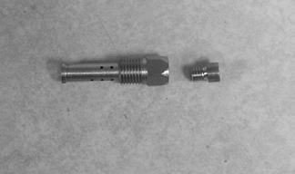
5.Remove the jet holder; then remove the main jet from the jet holder.
CD605
6.Remove the slow jet.

CD606
CLEANING AND INSPECTING ! WARNING
When drying components with compressed air, always wear safety glasses.
CAUTION
DO NOT place any non-metallic components in partscleaning solvent because damage or deterioration will result.
1.Place all metallic components in a wire basket and submerge in carburetor cleaner. 2.Soak for 30 minutes; then rinse with fresh partscleaning solvent. 3.Wash all non-metallic components with soap and water. Rinse thoroughly. 4.Dry all components with compressed air only making sure all holes, orifices, and channels are unobstructed.
5.Inspect the carburetor body for cracks, nicks, stripped threads, and any other imperfections in the casting. 6.Inspect float for damage. 7.Inspect gasket, seal, and O-rings for distortion, tears, or noticeable damage. 8.Inspect tips of the jet needle, pilot screw, and the needle valve for wear, damage, or distortion. 9.Inspect the slow jet and main jet for obstructions or damage.
NOTE: If the slow jet is obstructed, the mixture will
be extremely lean at idle and part-throttle operation.
10.Inspect the choke assembly for wear or damage.
ASSEMBLING 1.Install the slow jet.
CD606
2.Install the main jet by threading it into the jet holder; then install the jet holder into the carburetor. Tighten both components securely.
CD604
3.Install the idle adjustment screw with the spring. NOTE: Turn the idle adjustment screw clockwise
until lightly seated; then turn it counterclockwise 2-1/2 turns out.
4.Install the float and needle valve assembly into the carburetor; then install the float pin.
CD763
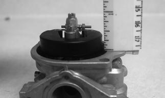
NOTE: Check float height by inverting the carbure-
tor freeing the float arm; then measure with a ruler the height when the float arm is in contact with the needle valve. Float height should be 10.2 mm (0.40 in.). To adjust, bend the actuator arm tab.
CD615
5.Install the float chamber seal.
CD601
6.Place the float chamber into position making sure the seal is properly seated; then secure with the Phillipshead screws and washers.
CD600
7.Install the choke assembly. Tighten the two Phillipshead screws (with washers) securely.
CD598
8.Insert the throttle cable into the top of the cap assembly and through the spring. 9.Compress the spring to expose the end of the throttle cable; then hook the end of the cable into the throttle valve. Release tension on the spring to hold the throttle cable.
INSTALLING 1.Install the throttle valve into the carburetor with the machined groove engaging the guide pin; then install the jet needle, needle clip, needle clip plate, and gasket.
2.Thread the carburetor cap onto the carburetor; then tighten securely.
CD594
3.Connect the choke assembly connector.
YT222
4.Install the carburetor onto the intake manifold; then tighten the cap screws securely.
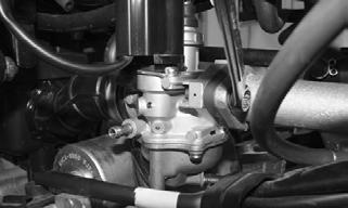
YT261
5.Install the air intake boot between the air filter and the carburetor. Secure with the clamp.
YT260
6. Install the float chamber drain hose and the vent hose to the carburetor.
7.Install the gas hose onto the carburetor.
Throttle Cable Free-Play
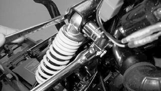
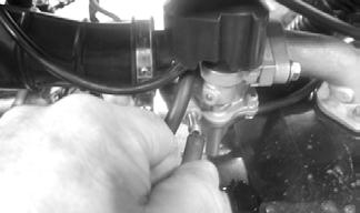
To adjust the throttle cable free-play, use the following procedure: 1.Pull back rubber boot to access cable adjustment nut.
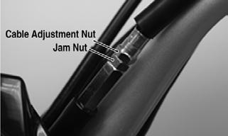
KM071A
2.Loosen jam nut to allow cable adjustment nut to be adjusted. 3.Turn cable adjustment nut clockwise to increase freeplay in the cable. Turn the adjustment nut counterclockwise to decrease free-play in the cable.
4.There should be approximately 6 mm (0.25 in.) freeplay in the cable. 5.Tighten the jam nut to secure the adjustment; then slide the rubber boot back into position.
Engine RPM (Idle)
NOTE: To properly adjust the idle RPM, a tachom-
eter is necessary.
1.Set the brake lever locks. Start the engine and warm it up to normal operating temperature.
2.Turn the idle adjustment screw in or out until the engine idles at 1700 RPM. Turning the screw clockwise will increase RPM; turning counterclockwise will decrease RPM.
CAUTION
Make sure the engine is fully warm before adjusting the idle RPM.
YT015B
Gas Tank
! WARNING
Whenever any maintenance or inspection is made on the fuel system during which there may be fuel leakage, there should be no welding, smoking, open flames, etc., in the area.
REMOVING 1.Turn the gas tank valve to the OFF position. 2.Remove the gas hose from the carburetor by removing the spring clamp; then funnel the gas hose into an appropriate container of sufficient size to catch all the gas from the gas tank. 3.Turn the gas tank valve to the RES position and drain the gas from the gas tank. 4.Remove the main body panel (see Steering/Body/
Controls — Body). 5.Remove the gas hoses from the gas tank valve.
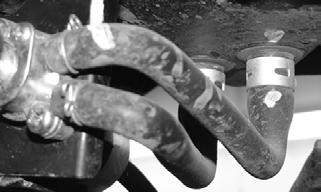
YT229
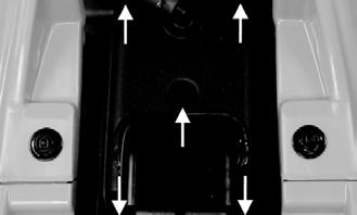
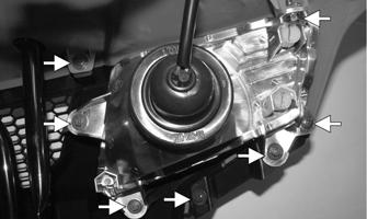
6.Remove the two cap screws securing the gas tank; then remove gas tank from vehicle.
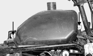
YT230A
CLEANING AND INSPECTING 1.Clean all gas tank components with parts-cleaning solvent.
2.Inspect all hoses for cracks or leaks. 3.Inspect gas tank cap and tank for leaks, holes, and damaged threads.
INSTALLING 1.Place the gas tank into position on the frame; then install the gas hoses to the gas tank valve on the frame according to the marks made during removing.
YT229
CAUTION
Do not over-tighten the cap screws securing the gas tank.
YT230A
3.Install the main body panel (see Steering/Body/Controls — Body).
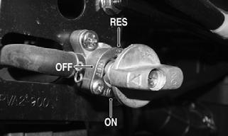
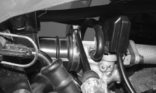
Gas Tank Valve
This ATV has a valve mounted on the side of the frame separate from the gas tank. There are three positions: ON, RES, and OFF.

YT251A
In the OFF position, the valve will not allow gasoline to flow to the carburetor. In the ON position (the normal operating position), gasoline will flow from the tank to the carburetor. In this position, 1.3 L (0.34 U.S. gal.) of gasoline will remain in the tank as a reserve quantity. Moving the valve to the RES position will allow the operator to use the remaining gasoline in the tank. When turning the valve to any of the three positions, be sure the indicator is pointed directly at the position desired.
REMOVING/INSPECTING ! WARNING
Drain the gas tank prior to this procedure.
1.Remove the cap screws securing the valve to the frame; then pull the valve out far enough to gain access to the three gas hoses (two to the gas tank, one to the carburetor). 2.Remove the gas hoses from the valve by releasing the spring clamps. 3.Inspect for and remove any obstructions in the valve.
INSTALLING 1.Install the gas hoses onto the valve with the spring clamps. 2.Place the valve into position on the frame and secure with the cap screws. Tighten securely.
Troubleshooting
Problem: Starting impaired Condition Remedy
1. Carburetor leaking air 1.Tighten — adjust carburetor — replace gasket 2. Choke not operating properly 2.Check choke assembly
Problem: Idling or low speed impaired Condition Remedy
1. Slow jet obstructed — loose 1.Clean — tighten jet 2. Needle jet obstructed 2.Clean jet 3. Pilot screw setting incorrect 3.Adjust pilot screw 4. Float level incorrect 4.Adjust float arm height
Problem: Medium or high speed impaired Condition Remedy
1. Main jet obstructed 1.Clean main jet 2. Needle jet obstructed 2.Clean needle jet 3. Throttle valve not operating properly 3.Check throttle valve operation 4. Filter obstructed 4.Clean filter 5. Float level incorrect 5.Adjust float arm height
Problem: Overflow and fuel level fluctuations Condition Remedy
1. Needle valve worn — damaged — dirty 1.Clean — replace needle valve 2. Float not working properly 2.Adjust float arm height — replace float 3. Float level too high — too low 3.Adjust float arm height