10 minute read
2.6 Adjusting valve timing

– Screw in lock ring - VAS 611 007/2- -B- max. 2 turns by hand. – Make sure that the shaft is free to move.
• Adapter for angle sensor - VAS 611 007/9- and adapter for angle sensor - VAS 611 007/10- should turn easily.
Advertisement
2.4.2 Installing test tool - VAS 611 007-
Special tools and workshop equipment required ♦ Test tool - VAS 611 007-
Procedure
– Preassemble test tool - VAS 611 007⇒ “2.4.1 Preassembling test tool VAS 611 007 ”, page 180 . – Teach-in test tool - VAS 611 007- electronically and perform basic setting ⇒ page 185 – Turn adapter for angle sensor - VAS 611 007/9- and adapter for angle sensor - VAS 611 007/10- until display is set to ap‐prox. 0°. – Perform the preliminary work for checking the valve timing ⇒ “2.5 Checking valve timing”, page 187 . – Make sure that the piston in cylinder no. 1 is at TDC position ⇒ “4.7 Setting piston to TDC position”, page 155 . – Make sure that brakes on angle sensor - VAS 611 007/1- are released on both sides ⇒ page 182 .
Note

Protected by copyright. Copying for private or commercial purposes, in part or in whole, is not permitted unless authorised by SEAT S.A. SEAT S.A does not guarantee or accept any liability with respect to the correctness of information in this document. Copyright by SEAT S.A.

Before positioning the test tool - VAS 611 007- against the cam‐shaft housing, the grooves of the camshafts must be checked for damage.
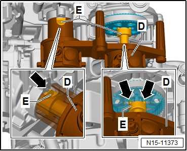
– Align adapter for angle sensor -E- by hand with grooves of camshafts -arrows-.
– Check proper alignment through recess, and adapt position by turning.
– Fit adapter for camshaft housing - VAS 611 007/8- -D- to cam‐shaft housing, and slide it on. – Tighten knurled screws -arrows a- alternately by hand. – Make sure that adapter for camshaft housing - VAS 611 007/8-D- is properly seated.
Note
♦ If the adapter for camshaft housing - VAS 611 007/8- -D- hits against the housing of the coolant pump, the basic setting is incorrect.
♦ Correcting the setting or valve timing is not possible in this case.
♦ The coolant pump must be removed and reset. ⇒ “2.5 Removing and installing coolant pump”, page 286
• Test tool - VAS 611 007- must rest flush against camshaft housing. – Make sure that brakes on angle sensor - VAS 611 007/1- are released on both sides ⇒ page 182 .
– Tighten locking ring - VAS 611 007/2- -B- on both sides evenly by hand. When doing this, ensure that camshaft housing adapter - VAS 611 007/8- -D- always lies flat against camshaft housing -1-.
Protected by copyright. Copying for private or commercial purposes, in part or in whole, is not permitted unless authorised by SEAT S.A. SEAT S.A does not guarantee or accept any liability with respect to the correctness of information in this document. Copyright by SEAT S.A.
• Camshaft housing adapter - VAS 611 007/8- -D- should not lift off of camshaft housing -1-.
Note
The correct preload is achieved when the camshaft housing adapter - VAS 611 007/8- lies flat -a- against the camshaft hous‐ing.
– Make sure that brakes -a- are released on both sides.
2.4.3 Teaching in test tool - VAS 611 007electronically and performing basic set‐ting
Special tools and workshop equipment required ♦ Test tool - VAS 611 007-
Protected by copyright. Copying for private or commercial purposes, in part or in whole, is not permitted unless authorised by SEAT S.A. SEAT S.A does not guarantee or accept any liability with respect to the correctness of information in this document. Copyright by SEAT S.A.
Procedure
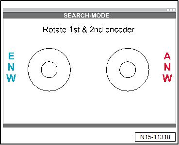
– Connect electronic measuring equipment of test tool - VAS 611 007- ⇒ Operating manual . – Perform software installation of test tool - VAS 611 007- ⇒ Operating manual . – Start test program ⇒ Operating manual . If angle sensors are not connected, message shown in illustration is displayed. – Connect test tool - VAS 611 007- , and press CONNECT .
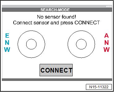
If test tool - VAS 611 007- is connected, display is as shown: ANW - Exhaust camshaft, red
ENW - Inlet camshaft, blue
– Turn adapter for angle sensor - VAS 611 007/10- red -E- for exhaust camshaft.
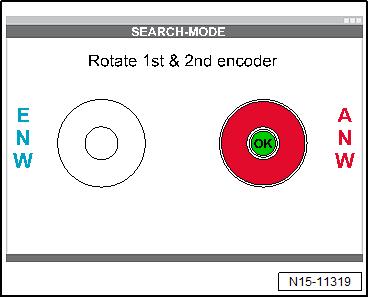
If OK is displayed, exhaust camshaft has been taught-in. – Turn adapter for angle sensor - VAS 611 007/9- blue -E- for intake camshaft.
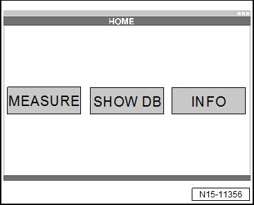
If display is as shown in illustration, exhaust camshaft has been taught-in. – Select function MEASURE .
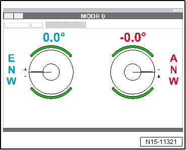
If angle display is as follows: – Check valve timing ⇒ “2.5 Checking valve timing”, page 187 .
Protected by copyright. Copying for private or commercial purposes, in part or in whole, is not permitted unless authorised by SEAT S.A. SEAT S.A does not guarantee or accept any liability with respect to the correctness of information in this document. Copyright by SEAT S.A.
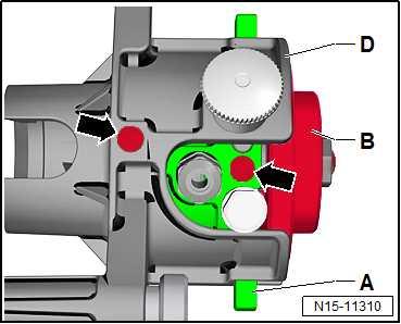
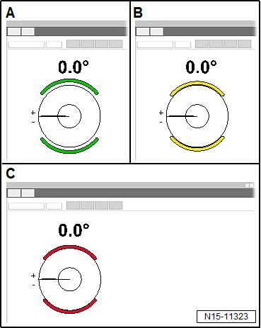
– Make sure that brake indicator on display is green. • It must not be yellow or red. A - Green, brake is released
B - Yellow, brake is applied C - Red, brake has been tightened to torque
2.5 Checking valve timing
Special tools and workshop equipment required ♦ Test tool - VAS 611 007-
Procedure
• Toothed belt installed.
Preparations – Remove air filter housing ⇒ “3.2 Removing and installing air filter housing”, page 397 . – Drain coolant ⇒ “1.3 Draining and adding coolant”, page 260 . – Loosen bolts -2-.
– Remove cover for thermostat housing -1-.
Protected by copyright. Copying for private or commercial purposes, in part or in whole, is not permitted unless authorised by SEAT S.A. SEAT S.A does not guarantee or accept any liability with respect to the correctness of information in this document. Copyright by SEAT S.A.
– Unclip wiring harness -3- and place to one side. – Remove screws -1-.
– Place a cloth underneath to catch any oil which may drain out. – Remove the plugs -5-. – Pull off pipe -2-. – Remove toothed belt cover -4-.
– Set piston for cylinder no. 1 to TDC position ⇒ “4.7 Setting piston to TDC position”, page 155 . – Preassemble test tool - VAS 611 007⇒ “2.4.1 Preassembling test tool VAS 611 007 ”, page 180 . – Install test tool - VAS 611 007⇒ “2.4.2 Installing test tool VAS 611 007 ”, page 183 . – Make sure that brakes -a- are released on both sides.
– Make sure that brake indicator on display is green -A-. • It must not be yellow or red.
Protected by copyright. Copying for private or commercial purposes, in part or in whole, is not permitted unless authorised by SEAT S.A. SEAT S.A does not guarantee or accept any liability with respect to the correctness of information in this document. Copyright by SEAT S.A.
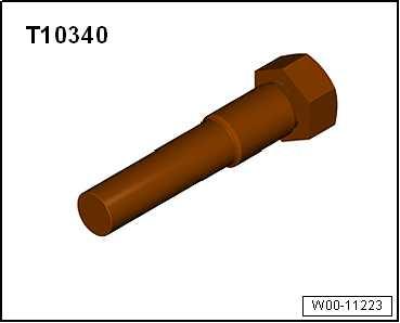
– Unscrew locking pin - T10340- -A-. – Turn crankshaft 2 turns in direction of rotation of engine. – Screw in locking pin - T10340- -A-. – Set piston for cylinder no. 1 to TDC position ⇒ “4.7 Setting piston to TDC position”, page 155 .
– Read valve timing angles on display, and compare values with specifications.
Specified values
Inlet camshaft
+1.1° ±1.5° Exhaust camshaft
+0.8° ±1.5°
NOTICE
Adjust valve timing as precisely as possible. The settings must be as close to the specifications as possible. The valve timing must not be outside the tolerance limits.
– If necessary, adjust timing ⇒ “2.6 Adjusting valve timing”, page 189 . Assembly is carried out in the reverse order. Observe the follow‐ing: – Add coolant ⇒ “1.3 Draining and adding coolant”, page 260 . Specified torques ♦ ⇒ “2.1 Assembly overview - coolant pump, thermostat”, page 278 ♦ ⇒ “3.1 Assembly overview - air filter housing”, page 393
Component Specified torque Bolt for TDC hole in cylinder block 30 Nm
2.6 Adjusting valve timing
Special tools and workshop equipment required ♦ Locating bolt - T10340-
Protected by copyright. Copying for private or commercial purposes, in part or in whole, is not permitted unless authorised by SEAT S.A. SEAT S.A does not guarantee or accept any liability with respect to the correctness of information in this document. Copyright by SEAT S.A.
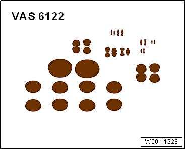
♦ Engine bung set - VAS 6122-
Procedure
• Toothed belt installed.
• Do not relieve tension from toothed belt, and do not remove toothed belt from camshafts when adjusting valve timing. Only loosen camshaft adjuster. – Check valve timing ⇒ “2.5 Checking valve timing”, page 187 . – Loosen camshaft adjuster on intake side ⇒ “3.4.1 Removing and installing camshaft adjuster for inlet camshaft”, page 211 . – Loosen camshaft adjuster on exhaust side ⇒ “3.4.2 Removing and installing camshaft adjuster for ex‐haust camshaft”, page 215 .
NOTICE
Protected by copyright. Copying for private or commercial purposes, in part or in whole, is notRisk of damage to engine caused by incorrect valve timing. – permitted unless authorised by SEAT S.A. SEAT S.A does not guarantee or accept any liability withDo not turn crankshaft out of TDC position.respect to the correctness of information in this document. Copyright by SEAT S.A.
– Place a cloth under the camshaft adjusters and over tension‐ing roller to catch the engine oil which runs out. • The contact points between the toothed belt and components such as camshaft pulleys, crankshaft pulley, tensioning roller and idler pulley must be free of oil. • Catch any engine oil which runs out immediately, and remove it.
• Remove any engine oil which ran out from camshaft adjusters after the engine has been cranked. – Make sure that the piston in cylinder no. 1 is at TDC position ⇒ “4.7 Setting piston to TDC position”, page 155 . – Renew bolts -3- and -4- and screw in loosely ⇒ “3.4 Removing and installing camshaft adjuster”, page 211 . • It should still be possible to turn camshaft adjusters -1- and -2- on camshafts.
Setting camshafts to 0° – Make sure that bolts -a- for brakes are released on both sides.
– Make sure that brake indicator on display is green -A-. – It must not be yellow or red.
– Set both camshafts to 0.0°.
Protected by copyright. Copying for private or commercial purposes, in part or in whole, is not permitted unless authorised by SEAT S.A. SEAT S.A does not guarantee or accept any liability with respect to the correctness of information in this document. Copyright by SEAT S.A.
