14 minute read
Suspension

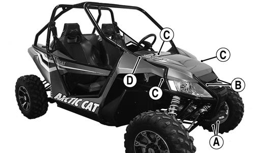
The following suspension system components should be inspected periodically to ensure proper operation.
A.Shock absorber rods bent, pitted, or damaged.
B.Reservoirs damp or leaking.
C.Shock absorber body damaged, punctured, or leaking.
D.Shock absorber eyelets broken, bent, or cracked.
E.Shock absorber eyelet bushings worn, deteriorated, cracked, or missing.
F.Shock absorber spring broken or sagging.
G.Sway bar mountings tight and bushings secure.
H.Proper pre-load and damping for conditions. SPECIAL TOOLS A number of special tools must be available to the technician when performing service procedures in this section. Refer to the current Special Tools Catalog for the appropriate tool description.
Shaft Bullet Tool Inflation Needle
Description p/n
0644-404 0744-020
Piston Location (IFP) Tool Gas Shock Rod/Body Clamping Tool 0644-575 0644-425
NOTE: Special tools are available from the Arctic
Cat Service Department.
Shock Absorbers
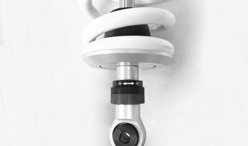
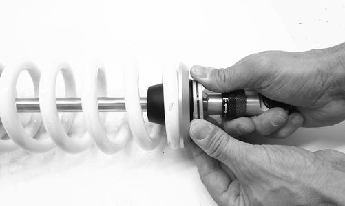
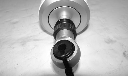
ADJUSTING SHOCK COMPRESSION (Wildcat/X/4X) NOTE: The JRI shock absorber comes with a 70-
position Compression Adjuster for a stiffer or a softer ride. The adjuster dial is located at the bottom of the shock.
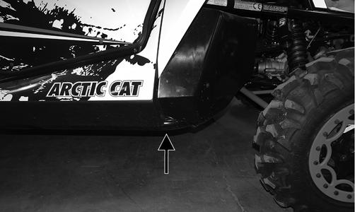
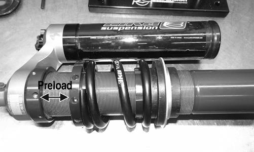
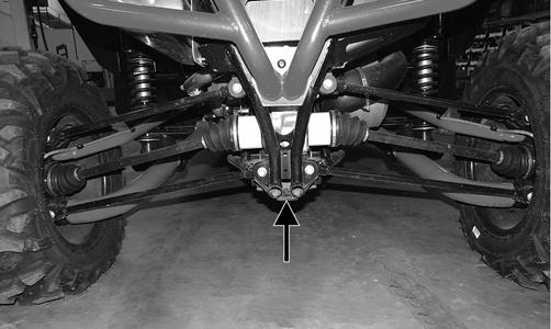
Turn the dial towards the + position for more compression (stiffer) or the - position for less compression (softer). REMOVING 1.Secure the vehicle on a support stand to elevate the wheels and release the load on the suspension. 2.Remove the two cap screws and nuts securing each front shock absorber to the frame and the lower Aarm. 3.Remove the two cap screws and nuts securing each rear shock absorber to the frame and the lower trailing arm. DISASSEMBLING (Wildcat/X/4X) NOTE: It is very important to measure the preload
with a tape measure before disassembling in order to return the spring to the proper preload setting.
WC901A
NOTE: Only the external parts are serviceable. If the
shock absorber is damaged, it must be replaced.
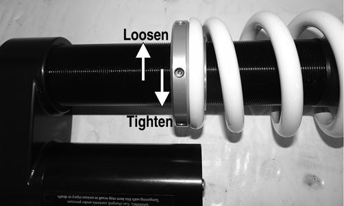
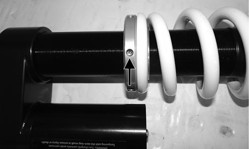
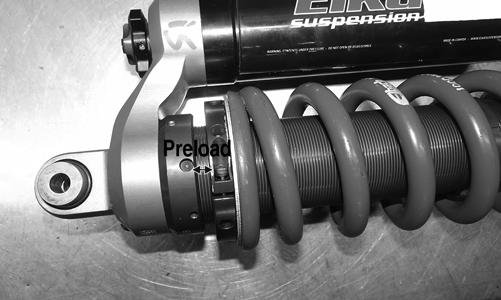
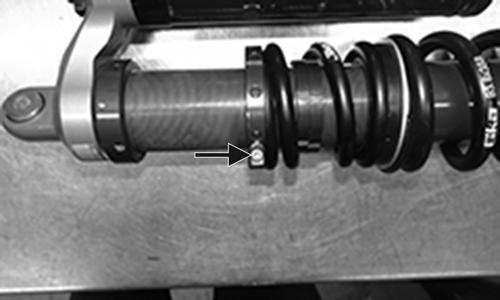
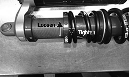
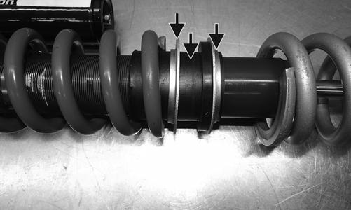
1.Loosen, but do not remove the lock ring screw.
WC905A
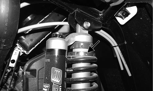
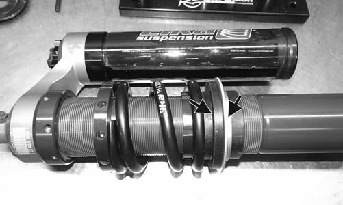
2.Loosen the lock ring towards the top of the shock until there is no pressure on the spring.
WC905B
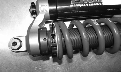
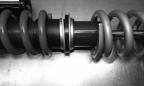
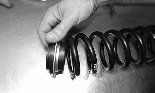
3.Push the spring and spring retainer upward toward the lock ring.
WC904
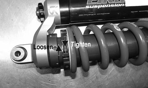
3.Tighten the lock ring until preload is at the measurement noted during cleaning and inspecting; then tighten the lock ring screw securely. NOTE: When tightening the lock ring, the spring
retainer must be past the snap ring retainer.
WC904
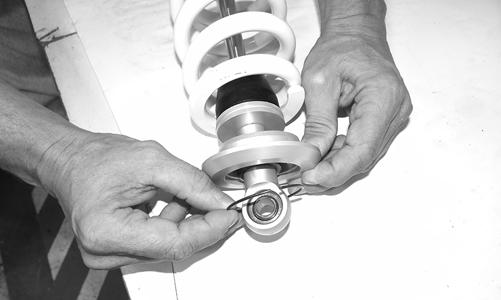
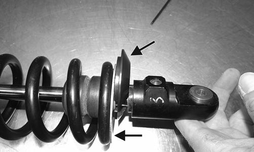
4.Remove the snap ring from the spring retainer, and remove the spring retainer and the snap ring.
WC906
5.Remove the spring. ASSEMBLING (Wildcat/X/4X) 1.Slide the spring up to the lock ring. 2.Slide the spring retainer past the snap ring retainer and secure the snap ring.
WC909
CHECKING/ADJUSTING RIDE HEIGHT (X Limited/4X Limited) NOTE: Ensure the vehicle is on level ground, the
tires are properly inflated, and there is an average operating load in the vehicle.
Front 1.Measure from the ground to the bottom of the outer frame tube.
WC911A
2.If measurement is not as specified, loosen, but do not remove, the lock ring screw.
Front
WC914A
3.Adjust the left and right spring as required. Rear 1.Measure from the ground to the bottom of the frame at the rear most point.
Rear
WC786A
WC913A
2.If measurement is not as specified, loosen, but do not remove, the lock ring screw.
WC789C
NOTE: Only the external parts are serviceable. If the
shock absorber is damaged, it must be replaced.
1.Loosen, but do not remove, the lock ring screw.
3.Adjust left and right spring as required.
WC912A
Model Front Rear
Wildcat EPS 13.25” 13.0” Wildcat X EPS 13.75” 13.5” Wildcat 4X 13.75” 13.5” Wildcat 4X LTD 13.75” 13.5” Wildcat X LTD 13.75” 13.5”
DISASSEMBLING (X Limited/4X Limited) NOTE: It is very important to measure the preload
with a tape measure before disassembling in order to return the spring to the proper preload setting.
Front
Rear
WC778A
WC789A
2.Loosen the lock ring towards the top of the shock until there is no pressure on the springs.
Front
Rear
WC778B
WC789B
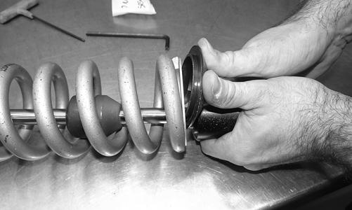
3.Remove the spring retainer and spring support plates.
Front
WC781A WC783
NOTE: Note the orientation of the spring retainer for
installing purposes.
5.Remove the top spring. 6.Clean all of the shock absorber components in a partscleaning solvent. 7.Inspect each shock rod for nicks, pits, rust, bends, and oil residue. 8.Inspect all of the spring retainers, shock rods, spring couplers, shock bodies, and eyelets for cracks, leaks, or bends. ASSEMBLING (X Limited/4X Limited) Front 1.With the proper orientation, slide the top spring, spring coupler, and spring support plate up to the lock ring.
WC786B
2.Install the main spring up to the spring support plate. 3.With the lower support plate in position, install the spring retainer.
Rear
WC793
4.Remove the main spring, spring coupler, and retaining plates.
WC795
4.Install the shocks using the two cap screws and nuts.
Tighten the screws to 40 ft-lb. Rear 1.With the proper orientation, slide the top spring and spring support plate up to the lock ring.
WC792
2.With the support plates facing opposite directions on the spring coupler, slide the coupler into the upper spring; then slide the lower spring into position.
WC794A
3.With the lower support plate in position, install the spring retainer.
WC 795
INSTALLING 1.Install the shocks using the two cap screws and new lock nuts. Tighten the upper rear cap screw to 40 ft-lb and the lower rear cap screws to 35 ft-lb. 2.Install the wheels and remove the vehicle from the stand.
Front A-Arms
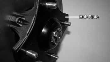
REMOVING 1.Secure the vehicle on a support stand to elevate the front wheels; then remove the wheels and account for the hub plate. NOTE: The upper A-arms can be removed without
removing the hub or knuckle. If the technician’s objective is to remove the upper A-arms, proceed to step 6.
WC240B
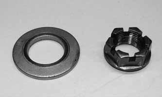
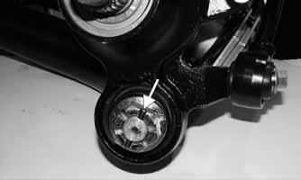
2.Remove the hub nut and Belleville washer securing the hub.
WC304
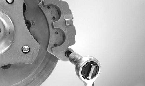
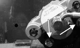
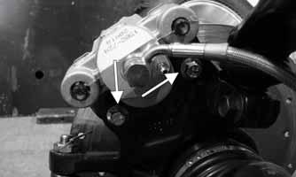
3.Remove the brake caliper. On the X/4X, account for two E-clips and two anchor bolts.
X/4X
Wildcat
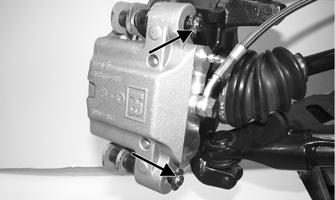
WC611A
X/4X
WC606
CAUTION
Support the knuckle when removing the cap screws or damage to the threads will occur.
WC271
7.Tap the ball joints out of the knuckle; then remove the knuckle from the axle. 8.Remove the lower shock absorber eyelet from the lower A-arm. 9.Remove the brakeline hose routing clips from the upper A-arm; then remove the cap screws securing the
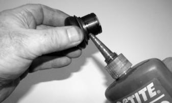
A-arms to the frame. CLEANING AND INSPECTING 1.Clean all A-arm components in parts-cleaning solvent. 2.Clean the ball joint mounting hole of all residual Loctite, grease, oil, or dirt for installing purposes. 3.Inspect the A-arm for bends, cracks, and worn bushings. 4.Inspect the ball joint mounting holes for cracks or damage. 5.Inspect the frame mounts for signs of damage, wear, or weldment damage. INSTALLING 1.Apply Loctite Primer “T” to the A-arm socket; then apply green Loctite #609 to the entire outside diameter of the ball joint. Install the ball joint into the A-arm and secure with the snap ring.
WC268A
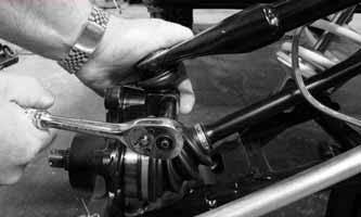
4.Remove the hub assembly. On the 4X, account for the washer. 5.Remove the cotter pin and nut securing the tie rod end to the knuckle; then remove the tie rod end from the knuckle. 6.Remove and discard the cap screws securing the ball joints to the knuckle.
WC237

WC359
2.Install the A-arm assemblies into the frame mounts and secure with the cap screws. Only finger-tighten at this time. 3.Route the brake hose along the upper A-arm and secure with the two routing clips. 4.Secure the lower eyelet of the shock absorber to the lower A-arm. Tighten nut to 40 ft-lb (head side). 5.Secure the A-arm assemblies to the frame mounts (from step 2). Tighten the cap screws to 40 ft-lb. 6.Install the knuckle assembly onto the ball joints and secure with new “patch-lock” cap screws. Tighten to 35 ft-lb.

WC271
7.Install the tie rod end and secure with the nut (coated with red Loctite #271). Tighten to 55 ft-lb; then install a new cotter pin and spread the pin to secure the nut. NOTE: During assembly, new cotter pins should be
installed.
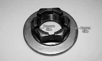
8.Apply Loctite primer and red Loctite #277 to the threads of the axle. 9.Engage the hub nut into the Belleville washer on the convex side; then with the concave side of the washer directed toward the hub, install the nut and washer.
Keeping the nut and washer engaged, tighten the hub nut to 250 ft-lb.

WC303A
10.Secure the brake caliper to the knuckle with two new “patch-lock” cap screws. On the X/4X, ensure the Eclips and anchor bolts are in place. Tighten to 20 ft-lb.
Wildcat
WC268A
WC606
X/4X
WC611A
11.Install the hub plate making sure it fits completely over the nut and lies flat against the hub.
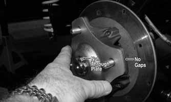
WC317A
NOTE: If the hub plate cannot be fully installed due
to misalignment of the hub nut, tighten the nut until properly aligned and plate is fully installed.
12.Install the wheel; then using a crisscross pattern, tighten the wheel nuts in 20 ft-lb increments to a final torque factor of 60 ft-lb (black lug nuts) or 80 ft-lb (aluminum lug nuts). Install the hub cap. 13.Remove the vehicle from the support stand.
Rear Trailing Arms
REMOVING 1.Lift and support the vehicle on support stands that allow access to the rear suspension with the rear tires off the floor. 2.Remove the hub cap and lug nuts securing the wheel; then remove the hub plate.

WC317
3.Place a jack stand or other support under the trailing arm; then remove the cap screw securing the lower shock eyelet to the arm. Account for a flat washer.
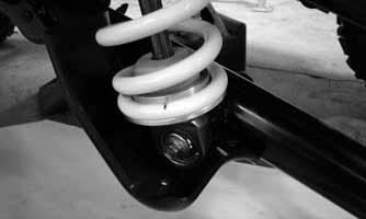
WC300
4.Remove the hub nut and Belleville washer securing the hub. 5.Remove and discard the cap screws securing the brake caliper to the knuckle and remove the caliper from the knuckle; then remove the hub/brake disc assembly.
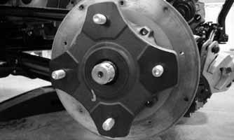
WC314
6.Remove the sway bar link; then remove the nut from the front trailing arm cross-mount through-bolt but do not remove the bolt at this time.
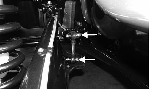
WC807A
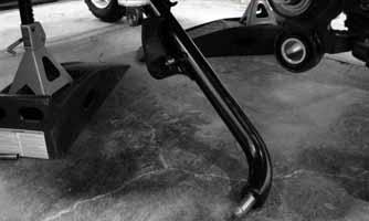
7.Using a tarp strap or nylon straps, support the suspension/axle assembly and remove the support from under the trailing arm. 8.Drive the roll-pin out and remove the nut from the trailing arm rear knuckle pivot; then remove the forward cross-mount bolt and remove the lower trailing arm.
WC305A
INSPECTING 1.Inspect the arm for any signs of metal fatigue, cracked or broken welds, or severe dents or gouges. 2.Check the pivot seals and bushings for signs of dirt or water contamination and corrosion. 3.Check the knuckle pivot bushing for excessive wear. 4.Check the shock mount for wear or fatigue cracks where welded to the arm surface. INSTALLING 1.Using new seals, install the front cross-mount onto the lower trailing arm and tighten the nut to 60 ft-lb; then place the assembly into the vehicle and secure with the cross-mount through-bolt. Tighten the nut to 60 ft-lb.
WC311
2.Slide the trailing arm into the knuckle and secure with the nut. Tighten the nut to 60 ft-lb; then install a new roll-pin.
WC305A
NOTE: If the slots in the nut do not align so as to allow
installation of the roll-pin, TIGHTEN the nut until the pin can be installed. DO NOT loosen the nut to align.
3.Place a jack stand or other suitable support under the trailing arm and install the sway bar link. Tighten the cap screw on the trailing arm and the nut on the sway bar bolt to 35 ft-lb.
WC807A
4.Slide the shock eyelet bushing over the shock mounting boss and secure with the cap screw and washer. Tighten to 40 ft-lb (head side). 5.Install the hub/brake disc assembly onto the axle; then apply Loctite primer and red Loctite #277 to the axle threads. 6.Engage the hub nut into the Belleville washer on the convex side; then with the concave side of the washer directed toward the hub, install the nut and washer. Keeping the nut and washer engaged, tighten the hub nut to 250 ft-lb.
WC303A
7.Install the brake caliper and secure with new “patchlock” cap screws tightened to 20 ft-lb. 8.Install the hub plate making sure it fits completely over the nut and lies flat against the hub.
WC317A
NOTE: If the hub plate cannot be fully installed due
to misalignment of the hub nut, tighten the nut until properly aligned and plate is fully installed.
9.Install the wheel; then using a crisscross pattern, tighten the wheel nuts in 20 ft-lb increments to a final torque factor of 60 ft-lb (black lug nuts) or 80 ft-lb (aluminum lug nuts). Install the hub cap. 10.Remove the support stands and lower to the floor.
Wheels and Tires
TIRE SIZE
! WARNING
Use only Arctic Cat approved tires when replacing tires. Failure to do so could result in unstable vehicle operation.
The Wildcat is equipped with low-pressure tubeless tires of the size and type listed in General Information. Do not under any circumstances substitute tires of a different type or size.
! WARNING
Always use the size and type of tires specified. Always maintain proper tire inflation pressure. Do not mix tire tread patterns. Use the same pattern type on front and rear. Failure to heed warning could cause poor handling qualities of the vehicle and could cause excessive drive train damage not covered by warranty.
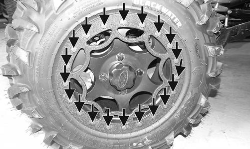
WC774A
TIRE INFLATION PRESSURE Front and rear tire inflation pressure should be as specified in the General Information section. REMOVING 1.Secure the vehicle on a support stand to elevate the wheels; then remove the hub cap. 2.Remove the nuts securing the wheels; then remove the wheels. NOTE: On Limited models, the bead lock must be
removed before attempting to remove the tire from the rim.
CLEANING AND INSPECTING 1.Clean the wheels and hubs with parts-cleaning solvent. 2.Clean the tires with soap and water. 3.Inspect each wheel for cracks, dents, or bends. 4.Inspect each tire for cuts, wear, missing lugs, and leaks. INSTALLING NOTE: On Limited models if a new tire is being
installed, install the bead lock and tighten the existing screws to 11 ft-lb.
1.Install the wheel. 2.Using a crisscross pattern, tighten the wheel nuts in 20 ft-lb increments to a final torque factor of 60 ft-lb (black lug nuts) or 80 ft-lb (aluminum lug nuts).
Install the hub cap. CHECKING/INFLATING 1.Using an air pressure gauge, measure the air pressure in each tire. Adjust the air pressure as necessary to meet the recommended inflation pressure. 2.Inspect the tires for damage, wear, or punctures.
! WARNING
Do not operate the vehicle if tire damage exists.
Troubleshooting
Problem: Suspension too soft Condition Remedy
1. Spring preload incorrect 1.Adjust preload 2. Spring(s) weak 2.Replace spring(s) 3. Shock absorber damaged 3.Replace shock absorber
Problem: Suspension too stiff Condition Remedy
1. Spring preload incorrect 1.Adjust preload 2. A-arm-related bushings worn 2.Replace bushing
Problem: Suspension noisy Condition Remedy
1. Cap screws (suspension system) loose 1.Tighten cap screws 2. A-arm-related bushings worn 2.Replace bushings
Problem: Vehicle pulling or steering erratic Condition Remedy
1. Vehicle steering is erratic on dry, level surface 1.Check front wheel alignment and adjust if necessary (see Steering/Frame/Controls) 2. Vehicle pulls left or right on dry, level surface 2.Check air pressure in tires and adjust to specifications
Printed in U.S.A. Trademarks of Arctic Cat Inc., Thief River Falls, MN 56701 p/n 2260-414