29 minute read
General Information

NOTE: General specifications for each 2015 Arctic Cat Snowmobile can be accessed from the Arctic Cat Cat Tracker Dealer Communication System online.
NOTE: Some illustrations and photographs used in this section are used for clarity purposes only and are not designed to depict actual conditions.
Snowmobile Identification
The Arctic Cat Snowmobile has two important identification numbers. The Vehicle Identification Number (VIN) is stamped into the tunnel near the right-side footrest or on top of the tunnel. The decal also displays pertinent production information. The Engine Serial Number (ESN) is stamped into the crankcase of the engine. These numbers are required to complete warranty claims properly. No warranty will be allowed by Arctic Cat if the engine serial number or VIN is removed or mutilated in any way.
Recommended Gasoline and Oil
CAUTION
Do not use white gas or gasoline containing methanol. Only Arctic Cat approved gasoline additives should be used. CAUTION
Any oil used in place of the recommended oil may cause serious damage. RECOMMENDED GASOLINE The recommended gasoline to use in these snowmobiles is 87 octane regular unleaded. In many areas, oxygenates are added to the gasoline. Oxygenated gasolines containing up to 10% ethanol are acceptable gasolines; however, on the 2000 whenever using oxygenated gasolines, the carburetor main jet must be one size larger than the main jet required for regular unleaded gasoline. For example, if a 220 main jet is recommended for regular unleaded gasoline, a 230 main jet must be installed if using an oxygenated gasoline. When using ethanol blended gasoline, adding a gasoline antifreeze is not necessary since ethanol will prevent the accumulation of moisture in the fuel system. RECOMMENDED OIL (2000) The recommended oil to use in the oil-injection system is Arctic Cat Formula 50 Injection Oil. These oils are specially formulated to be used either as an injection oil or as a pre-mix oil (for break-in) and meets all of the lubrication requirements of the Arctic Cat snowmobile engine.
Any oil used in place of the recommended oil could cause serious engine damage.
RECOMMENDED OIL (5000) The recommended oil to use is Synthetic 0W-40 Oil in all temperatures and conditions.
OILCHARTJ After the engine break-in period, the engine oil should be changed every 2500-3000 miles and before prolonged storage.
Engine Break-In
2000 The Arctic Cat 2000 engine (when new or rebuilt) requires a short break-in period before the engine is subjected to heavy load conditions. Arctic Cat requires that the first tankful of fuel be premixed at a 100:1 ratio in all oil-injection models. During the break-in period, a maximum of 1/2 throttle is recommended; however, brief full-throttle accelerations and variations in driving speeds contribute to good engine break-in.
CAUTION
DO NOT exceed the one (1) tankful limitation of a 100:1 gas/oil break-in mixture. Continuous use of a gas/oil mixture could cause spark plug fouling and excessive carbon buildup. 5000 The Arctic Cat 5000 engine (when new or rebuilt) requires a short break-in period before the engine is subjected to heavy load conditions. This engine does not require any pre-mixed fuel during the break-in period.
To ensure trouble-free operation, careful adherence to the following break-in guidelines will be beneficial.
CAUTION
DO NOT use premixed fuel in the snowmobile gas tank. Engine damage will occur.
0-200 miles 200-400 miles 400-600 miles 1/2 Throttle (45 MPH-max) 1/2-3/4 Throttle 1/2-3/4 Throttle *
To ensure proper engine break-in, Arctic Cat recommends that the engine oil and filter be changed after 500 miles or after one month, whichever comes first. This service is at the discretion and expense of the snowmobile owner.
Drive Belt Break-In
Drive belts require a break-in period of approximately 25 miles. Drive the snowmobile for 25 miles at 3/4 throttle or less. By revving the engine up and down (but not exceeding 60 mph), the exposed cord on the side of a new belt will be worn down. This will allow the drive belt to gain its optimum flexibility and will extend drive belt life. NOTE: Before starting the snowmobile in extremely cold temperatures, the drive belt should be removed and warmed up to room temperature. Once the drive belt is at room temperature, install the drive belt (see Drive Belt sub-section in Drive Train/Track/Brake Systems section of this manual).
CAUTION
Running the engine with the drive belt removed could result in serious engine damage and drive clutch failure.
Genuine Parts
When replacement of parts is necessary, use only genuine Arctic Cat parts. They are precision-made to ensure high quality and correct fit.
Varying Altitude Operation
Operating a snowmobile at varying altitudes requires recalibration of carburetor and/or drive system components. The altitude information decal is located beneath the hood of the snowmobile on the belt guard.
Following are basic altitude theories for clutching, engine, suspension, and track. CLUTCHING On a normally-aspirated engine as altitude changes, engine horsepower changes with it. As you go up in altitude, the engine loses horsepower. Because of this, the continuously variable transmission (CVT) system needs to be calibrated to compensate for the horsepower loss.
CAUTION
On the 2000, carefully follow the Carburetor Jet Chart recommendations for proper carburetor calibration for altitude, temperature, and gasoline being used. At altitudes above 5000 ft, the engine loses peak horsepower but will also lose horsepower at engagement speed. For this reason, calibrating the drive system is usually needed in order to attain acceptable performance. Changing drive clutch engagement speed can be done several ways. Some of the methods will affect other characteristics of CVT operation, so you must be careful what you change. Drive clutch springs are the most common way to increase engagement speed; however, by simply changing the cam arms to a lighter weight from the heavier sea level cam arm, you will gain some engagement speed. Other more complicated methods exist such as engagement notches and changing the position of the cam arm center of gravity in relation to the roller. This is called “tucking the weight” and can be used, but, like the engagement notch, it can hurt belt life. The driven clutch will also play a part in CVT tuning for high altitude operation. A steeper helix (torque bracket) angle in the driven clutch will mean a quicker up-shift. A shallower angle will mean a slower up-shift. If the up-shift is too quick, due to a very steep helix, RPM will be pulled down under the peak operating RPM of the engine (where the horsepower is) and performance will suffer. The engine may even bog. If you have a helix that is too shallow, the engine may over-rev or have poor acceleration. Usually, angles shallower than the sea level calibrations work best. The driven spring will also affect driven clutch tuning. Tighten the spring, and RPM will increase. Loosen the spring, and RPM will decrease. The spring should be used to fine-tune and complement the helix selection. Carburetor calibration changes for high altitude operation will have an effect on the CVT system and how it operates. Understanding the basics of CVT operation is important in order to make the correct high altitude CVT calibration changes. ENGINE A normally aspirated engine will generate more horsepower at sea level than it does at higher altitudes. The reason is that the higher you go, less oxygen is available for the engine to use during its combustion process. Less oxygen means it needs less fuel to obtain the correct air/fuel ratio to operate properly. This is why the fuel ratio has to be recalibrated. High altitude engines operate as though they have a lower compression ratio. This, along with less oxygen and less fuel, means that the engine generates less horsepower. The carbureted models will also have lower pressure applied to the float chamber because of pressure changes in the atmosphere between high altitude and sea level. All of these characteristics will become more evident the higher the altitude. SUSPENSION The different riding styles of the individual operator, the varying snow conditions, and the type of terrain are all factors that affect the suspension at high altitude. Trail riding versus powder snow riding versus combination riding will all require different suspension settings. The normal setting for front ski suspension is as little spring pre-load tension as possible for powder snow riding allowing the skis to float across the snow with the least amount of resistance. Trail riding will require more spring tension to carry the varying load more effectively. Many different settings and spring tensions to consider exist when adjusting for riding style and snow conditions.
The rear suspension has a number of spring settings that produce different riding characteristics. The front arm spring and shock will also affect the ride and handling when either on a trail or in powder snow. A strong spring setting on this shock will cause the snowmobile to tend to “dig” more when riding in the powder snow rather than climbing up on top of the snow. But, it will work more effectively when riding on a trail. A softer spring setting will allow the front of the rear suspension to collapse much quicker and change the angle of the track to the snow. A more gradual angle will tend to raise the snowmobile up on the snow rather than digging into it. Many possible variables and adjustments to the rear suspension exist depending on snow conditions, riding style, and type of terrain. These adjustments can be made to individualize the snowmobile to the riding style of the operator. Finally, track tension should be looked at to make sure that it is within recommended specifications to affect the efficiency of the snowmobile. On models with the torque sensing link, the track is actually tightening as the suspension moves through its range of motion causing the track to sag in the middle and rub on the top part of the rear suspension arm. TRACK Carefully matching the riding requirements to the type of track will ensure the maximum use of all available engine power. Lug height and track durometer are the two main concerns when selecting a track for various riding styles. Tracks exist with lug heights from 0.750” up to 1.5” to accommodate various snow conditions. Generally, the deeper the snow, the taller the lug. It must be noted that the installation of any deep-lug track may reduce top end speed and promote premature wear strip wear in marginal snow conditions.
Preparation For Storage
Prior to storing the snowmobile, it must be properly serviced to prevent corrosion and component deterioration. 1. Clean the seat cushion with a damp cloth and Arctic
Cat Vinyl Protectant. 2. Clean the snowmobile thoroughly by hosing dirt, oil, grass, and other foreign matter from the skid frame, tunnel, hood, and belly pan. Allow the snowmobile to dry thoroughly. DO NOT get water into any part of the engine. 3. On the 5000, change the engine oil; then proceed to step 7. 4. Carefully pry the intake boots partially over the carburetor inlets/throttle body inlets. 5. Place the rear of the snowmobile up on a shielded safety stand; then start the engine and allow to idle.
Spray an Engine Storage Preserver into the intakes until the engine exhaust starts to smoke heavily or until the engine starts to drop in RPM. Turn engine off. Install the intake boots. 6. On the 2000 with the ignition switch in the OFF position:
A.Disconnect the high tension leads from the spark plugs; then remove the plugs, connect them to the leads, and ground them on the cylinder heads.
B.Pour 29.5 ml (1 fl oz) of SAE #30 petroleumbased oil into each spark plug hole and pull the recoil starter handle slowly about 10 times. C.Install the spark plugs and connect the high tension leads.
CAUTION CAUTION
Never crank the engine over without grounding the spark plugs. Damage to coils and/or ECM may result.
NOTE: At this point on the 2000, drain the gas from each carburetor float chamber.
7. Plug the exhaust system outlet with a clean cloth. 8. Fill the gas tank to its rated capacity; then add Arctic
Cat Fuel Stabilizer to the gas tank following directions on the container for the stabilizer/gasoline ratio. Tighten the gas tank cap securely. 9. Flush the gear case and change the lubricant (see
Drive Train/Track/Brake Systems section). 10. Remove the drive belt from the drive clutch/driven clutch (see Drive Train/Track/Brake Systems section). Lay the belt on a flat surface or slide it into a cardboard sleeve to prevent warping or distortion during storage; then clean and inspect the drive clutch and driven clutch. 11. Apply light oil to the upper steering post bushings and to the shafts of the shock absorbers; then lubricate the rear suspension with an all-temperature grease. 12. Lubricate the spindles and steering arm with an alltemperature grease. 13. Tighten all nuts, bolts, and cap screws making sure all calibrated nuts, bolts, and cap screws are tightened to specifications. Make sure all rivets holding the components together are tight. Replace all loose rivets. 14. Clean and polish the hood, console, and chassis with
Cat Cleaner. DO NOT USE SOLVENTS. THE PRO-
PELLENT WILL DAMAGE THE FINISH. 15. On electric start models, disconnect the battery cables making sure to disconnect the negative cable first; then clean the battery posts and cables.
CAUTION
Sealed batteries require charging if left for extended non-start periods. Arctic Cat recommends trickle charging once a month. Follow the manufacturer’s instructions and cautions.
CAUTION
On models with remote start, make sure to leave the battery cables disconnected. Failure to disconnect the battery cables when storing the snowmobile for a prolonged period of time (six weeks or more) will result in a discharged or damaged battery.
16. If possible, store the snowmobile indoors. Raise the track off the floor by blocking up the back end making sure the snowmobile is secure. Loosen the track adjusting bolts to reduce track tension. Cover the snowmobile with a machine cover or a heavy, ventilated tarpaulin to protect it from dirt and dust. 17. If the snowmobile must be stored outdoors, position the snowmobile out of direct sunlight; then block the entire snowmobile off the ground making sure the snowmobile is secure. Loosen the track adjusting bolts to reduce track tension. Cover with a machine cover or a heavy, ventilated tarpaulin to protect it from dirt, dust, and rain.
CAUTION
Avoid storing in direct sunlight and using a plastic cover as moisture may collect on the snowmobile causing corrosion.
Preparation After Storage
Taking the snowmobile out of storage and correctly preparing it for another season will assure many miles and hours of trouble-free snowmobiling. Arctic Cat recommends the following procedure:
CAUTION
On the 2000 if the gas in each carburetor float chamber was not drained prior to storage, the carburetors must be cleaned before starting the engine.
1. Clean the snowmobile thoroughly. Polish the exterior of the snowmobile. 2. Clean the engine. Remove the cloth from the exhaust system. Check exhaust system and air silencer for obstructions. 3. Inspect all control wires and cables for signs of wear or fraying. Replace if necessary. Use cable ties or tape to route wires and cables away from hot or rotating parts. 4. Inspect the drive belt for cracks and tears. Check belt specifications. Replace if damaged or worn. Install the drive belt (see Drive Train/Track/Brake Systems section). NOTE: If the old belt is worn but in reasonable condition, retain it with the snowmobile as a spare in case of emergency.
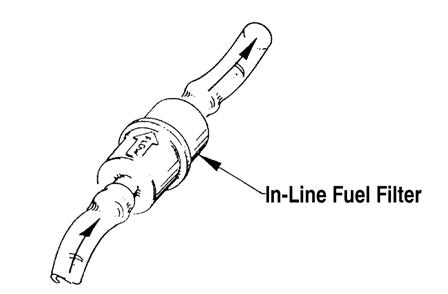
5. On the 2000, inspect the in-line fuel filter and replace if necessary; then adjust the carburetors and choke cable. ! WARNING
Be sure to tighten the swivel adapter jam nuts securely. If a jam nut isn’t tightened, the adjuster can rotate out of the carburetor cap causing the piston valve not to return to the full-closed position. 6. Adjust the throttle cable. Inspect all fuel hoses and oil hoses for deterioration or cracks; replace if necessary. Make sure all connections are tight. 7. On the 2000, fill the oil-injection reservoir with the recommended 2-cycle oil; then inspect each spark plug. Replace, gap, or clean as necessary.
NOTE: On the 2000 after prolonged storage, Arctic Cat recommends one tankful of 100:1 gas/oil mixture be used in conjunction with the oil-injection system to ensure proper lubrication.
8. Tighten all nuts, bolts, and cap screws making sure all calibrated nuts, bolts, and cap screws are tightened to specifications. 9. If not done during preparation for storage, lubricate the rear suspension with an all-temperature grease.
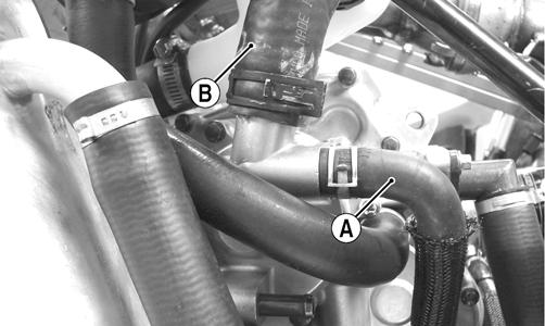
Lubricate the spindles and steering arm with an alltemperature grease. 10. On liquid cooled models, check the coolant level and all coolant hoses and connections for deterioration or cracks. Add properly mixed coolant as necessary. 11. On the 2000, clean the engine cooling fins and vents. 12. On electric start models, charge the battery; then connect the battery cables making sure to connect the positive cable first. Test the electric start system. 13. Inspect the entire brake system, all controls, headlight, taillight, brake light, ski wear bars, and headlight aim; adjust or replace as necessary. 14. Adjust the track to the proper tension and alignment.
After Break-In Checkup/ Checklist
Certain areas require adjustment after the break-in period in order to obtain peak performance. These areas are the following. CARBURETOR JETTING (2000) — Altitude, temperature, and the use of oxygenated gasoline affect the carburetion needed for optimum engine performance. The carburetor main jets must be changed in conjunction with changes in operating altitude, oxygenated gasoline usage, and temperature. DRIVE BELT DEFLECTION — Drive belt deflection is very important to the snowmobile. Even if it is checked and is correct when the snowmobile is set up, it does change (more so during the break-in period). This is because the rubber engine mounts and the rubber snubber on the torque link will all take a “set” during the first 100 miles allowing the distance between the drive clutch and driven clutch to shorten. When this happens, the snowmobile will appear to have a too long drive belt. To add to this, the drive belt itself wears and stretches somewhat leading to a low-end performance problem and, if not corrected, causes premature drive belt wear. After the break-in period, drive belt deflection should be checked according to the instructions given in Drive Train/Track/Brake Systems section of this manual. DRIVE CLUTCH/DRIVEN CLUTCH ALIGNMENT — The alignment between the drive clutch and driven clutch are set at the factory. Normally, no adjustment is necessary; however, if premature drive belt wear or poor performance is experienced, the drive clutch/driven clutch alignment must be checked.
TRACK TENSION AND ALIGNMENT — A certain amount of stretch occurs on all tracks during the first 500 miles. The track must be inspected/adjusted after the first 50 to 100 miles to the specifications given in the Track Specifications sub-section of this section and periodically thereafter. If these adjustments aren’t performed, the track may “derail” which leads to track and slide rail damage. Along with these major areas, other areas should be checked and adjusted. Below is a list of items to check after the break-in period. The recommended mileage for this inspection is between 100 and 300 miles.
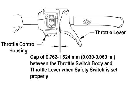
Jet carburetors according to average temperature, type of gasoline being used, and altitude (2000) Check drive belt deflection - drive clutch/driven clutch alignment Adjust track tension and alignment Check throttle cable tension Check oil-injection pump adjustment (2000) Check engine idle Check coolant level Check gear case lubricant level Check engine oil (5000) Check lights (high/low beam, brakelight) Check safety switch operation Check engine compartment for any rubbing components Check steering hardware for tightness Check skid frame and A-arm mounting hardware for tightness Check brake lever travel and adjustment Grease all lubrication points
Engine Specifications
2000
ITEM Engine Model Number AA56A9 Displacement 565 cc Bore x Stroke 73.8 x 66 Compression Ratio 6.41:1 Cooling System Fan Ignition Timing (Engine Warm) 20° @ 2000 RPM 0.099” Spark Plug (NGK) Spark Plug Gap BR9EYA 0.028-0.031”
Piston Skirt/Cylinder Clearance Piston Ring End Gap Cylinder Trueness Limit 0.0031-0.0041” 0.012-0.0196” 0.004”
Piston Pin Diameter
0.7085-0.7087” Piston Pin Bore Diameter 0.7087-0.7091” Connecting Rod Small End Bore 0.9056-0.9059” Connecting Rod Radial Play 0.0001-0.0008” Crankshaft Runout (t.i.r.) 0.002” Crankshaft End Play 0.002-0.004” Reed Stopper Height 0.236” 5000
ITEM 5000
Engine Model Number AA11L5 Displacement 1056 cc Bore x Stroke 98 x 70 Cooling System Liquid Spark Plug (NGK) MR8AI-9 Spark Plug Gap 0.035” Piston Skirt/Cylinder Clearance 0.0011-0.0016” Piston Pin Diameter 0.8658-0.8661” Piston Pin Bore Diameter 0.8662-0.8664” Piston Pin/Connecting Rod Small End Clearance 0.0004-0.0010” Piston Ring End Gap (1st) 0.0059-0.0138” (2nd) 0.0118-0.0177” (Oil) 0.0078-0.0275” Piston Ring/Groove Clearance (1st - Top) 0.0059-0.0074” (1st - Bottom) 0.0008-0.0035” (2nd) 0.0008-0.0024” (Oil) 0.0024-0.0059” Piston Diameter (10 mm from skirt edge) 3.8568-3.8574” Cylinder/Head Distortion (max) 0.002” Connecting Rod Small End Bore Inside Diameter 0.866-0.867” Cam Lobe Height (Int) 1.487-1.489” Cam Lobe Height (Exh) 1.432-1.433” Camshaft Journal Outside Diameter 0.8650-0.8658” Camshaft Journal Bore Diameter 0.8666-0.8670” Camshaft Journal Clearance 0.0007-0.0020” Crank Pin Diameter 1.7707-1.7720” Crankshaft Runout 0.002” Crankshaft Main Bearing Clearance 0.0007-0.0015” Crankshaft/Rod Bearing Clearance 0.0016-0.0025” Crankshaft Thrust Runout (max) 0.0043” Crankshaft Main/Rod Journals (Bearing Surfaces) 0.0012” Valve Guide Inside Diameter 0.2165-0.2170” Valve Guide/Stem Clearance (max) (Int) 0.0015” (Exh) 0.0022”
Valve Face Width 0.0197”
Valve Clearance - Cold (59°-77° F) (Int) (Exh) 0.0039-0.0078” 0.0078-0.0118”
Valve Seat Contact Width (Int/Exh)0.0354-0.0433”
Valve Stem Diameter
(Int) (Exh) 0.2155-0.2161” 0.2147-0.2153”
Crankshaft Runout/ Repair Specifications (2000)
To use the specifications, first refer to the drawing; then find the letter indicating the specification and refer to the chart below the illustration.
NOTE: The proper location for checking crankshaft runout is the very edge of the straight portion of the shaft where the oil seal makes contact. From the illustration, note that three check points are called out: at either end, out on the taper as shown, and also on the center bearing race. The crankshaft is still supported on the outer bearings using V blocks.
Carburetor Specifications (2000)
TYPE MAIN JET NEEDLE JET JET NEEDLE PILOT JET CUT-AWAY VM-34 220 P-4M (961) 6CE25-4 40 3.0 PILOT AIR SCREW FLOAT HEIGHT (TURNS OUT) (mm) 1 1/2 22-24
NOTE: The above specifications are production calibrations. For high altitude carburetion and drive system settings, refer to the jet chart on the snowmobile belt guard. For optional tuning components, see the POGA Reference Guide.
728-144A A ± 0.006 B ± 0.006 C G Runout D and F Point ± 0.002
4.70” 2.45” 4.320” 0.945” D 1.181”
F 0.590”
NOTE: Measure in from the shaft end the specified amount when checking runout at points D and F. When checking runout in the center, place indicator on center of bearing as shown at point E. Maximum runout at any of the three measuring points is ± 0.002”.
Component
Ignition Coil
Charge Coil (1) Charge Coil (2) Ignition Timing Sensor Lighting Coil Voltage Regulator/Rectifier*
Ignition Switch Oil Level Sensor Spark Plug Cap
Magneto Coil (three tests) Ignition Coil (1) Ignition Coil (2) Fuel Injector Crankshaft Position Sensor Test Value
(Primary) (Secondary) 2000 (Normally Open Ignition)
0.26-0.35 ohm 6800-10,200 ohms 12-18 ohms orange high tension wire brown/white
12-18 ohms black/red
148-222 ohms green/white
0.12-0.18 ohm 10-15 DC Volts 11-14 AC Volts
yellow red/blue yellow
Less than 1 ohm (key in OFF position)terminal Less than 1 ohm (float end down) terminal 4000-6000 ohms cap end 5000 (Normally Closed Ignition)
0.2-0.4 ohm 1.4 ohms 1.4 ohms yellow red/green red/green
9-12 ohms lead
173-211 ohms blue/white
Injection Coil 3.6 ohms
Voltage Regulator/Rectifier*
12-14.5 DC Volts Magneto Coil (no load) (three tests) 36-44 AC Volts black/yellow terminal yellow
Ignition Switch Oil Level Sensor Less than 1 ohm (key in OFF position)terminal Less than 1 ohm (float end down) terminal + Test Connections -
black/white high tension wire green/red green/red brown/green yellow brown brown
terminal terminal cap end
yellow gray/green brown/green lead green/white black terminal yellow terminal terminal
Spark Plug Cap 4000-6000 ohms cap end cap end
* Harness plugged in The main harness connectors must be unplugged (except on the primary coil and regulator/rectifier or CCU tests), the spark plugs removed and grounded (2000), and by pulling the recoil starter rope briskly. NOTE: Lighting coil output is unregulated voltage.
! WARNING
Most voltages generated by the ignition system are sufficient to interrupt pacemakers! All technicians, especially those using pacemakers, must avoid contact with all electrical connections when pulling the recoil starter rope or after the engine has been started.
Drive System Specifications
Drive Clutch/Driven Clutch-Related Specifications Drive System Components
Model Altitude Drive Clutch Spring Cam Arm Driven Clutch Spring Torque Bracket Drive Belt Engagement RPM Peak RPM Transfer Gear Input Gear Ratio
Bearcat 2000 0-5000 Black/White 73.0g Orange 46°/40° 0627-067 27-2900 66-6800 66/34T 54T 54/66 Bearcat 2000 XT/XTE 0-5000 Black/White 71.5g Orange 46°/40° 0627-046 27-2900 66-6800 66/34T 54T 54/66 Bearcat 5000 XT GS 0-5000 Black/White 66.0g Orange 36° 0627-073 28-3000 82-8400 66/34T 54T 54/66 Bearcat 5000 XT/LTD 0-5000 Black/White 66.0g Orange 36° 0627-047 28-3000 82-8400 66/34T 54T 54/66 Lynx 2000 0-5000 Black/Gold 73.0g Orange 44°/40° 0627-067 31-3300 66-6800 63/34T 57T 57/63 Lynx 2000 LT 0-5000 Black/Gold 73.0g Orange 44°/40° 0627-067 31-3300 66-6800 66/34T 54T 54/66
ALIGNMENT BAR OFFSET P/N CENTER-TO-CENTER OFFSET FLOAT 0644-496 11.50” (2000) 1.507” None 10.20” (5000) A list of Drive System components available through the Arctic Cat Service Parts Department can be found in the POGA Reference Guide. This information will be useful when doing any fine-tuning on the drive system.
Gear Case Performance Calibrations
Drive Sprocket Gear Ratio Engine RPM 6200 6400 6600 6800 7000 7200 7400 7600 7800 8000 8200 8400 8600 8800 9000 Vehicle Speed (mph)
9 Tooth (2.52” pitch) 66 54 91 94 97 100 103 106 109 112 114 117 120 123 126 129 132 65 55 88 91 94 96 99 102 105 108 111 113 116 119 122 125 128 64 56 85 88 91 93 96 99 102 104 107 110 112 115 118 121 123 63 57 82 85 88 90 93 96 98 101 103 106 109 111 114 117 119 62 58 80 82 85 87 90 92 95 98 100 103 105 108 110 113 115 61 59 77 79 82 84 87 89 92 94 97 99 102 104 107 109 112 60 60 74 77 79 82 84 86 89 91 94 96 98 101 103 106 108 59 61 72 74 77 79 81 84 86 88 91 93 95 98 100 102 104 58 62 70 72 74 76 79 81 83 85 88 90 92 94 97 99 101 57 63 67 70 72 74 76 78 80 83 85 87 89 91 93 96 98 56 64 65 67 69 71 74 76 78 80 82 84 86 88 90 92 95 55 65 63 65 67 69 71 73 75 77 79 81 83 85 87 89 91 54 66 61 63 65 67 69 71 73 75 77 79 81 83 84 86 88
10 Tooth (2.52” pitch) 66 54 101 104 108 111 114 117 121 124 127 130 134 137 140 143 147 65 55 98 101 104 107 110 113 117 120 123 126 129 132 136 139 142 64 56 95 98 101 104 107 110 113 116 119 122 125 128 131 134 137 63 57 91 94 97 100 103 106 109 112 115 118 121 124 127 130 133 62 58 88 91 94 97 100 103 106 108 111 114 117 120 123 125 128 61 59 85 88 91 94 97 99 102 105 108 110 113 116 119 121 124 60 60 83 85 88 91 93 96 99 101 104 107 109 112 115 117 120 59 61 80 83 85 88 90 93 95 98 101 103 106 108 111 114 116 58 62 77 80 82 85 87 90 92 95 97 100 102 105 107 110 112 57 63 75 77 80 82 84 87 89 92 94 97 99 101 104 106 109 56 64 72 75 77 79 82 84 86 89 91 93 96 98 100 103 105 55 65 70 72 74 77 79 81 84 86 88 90 93 95 97 99 102 54 66 68 70 72 74 76 79 81 83 85 87 89 92 94 96 98
10 Tooth (2.86” pitch)
66 54 103 106 109 113 116 119 123 126 129 133 136 139 143 146 149 65 55 99 103 106 109 112 115 119 122 125 128 131 135 138 141 144 64 56 96 99 102 105 109 112 115 118 121 124 127 130 133 136 140 63 57 93 96 99 102 105 108 111 114 117 120 123 126 129 132 135 62 58 90 93 96 99 101 104 107 110 113 116 119 122 125 128 130 61 59 87 90 93 95 98 101 104 107 109 112 115 118 121 123 126 60 60 84 87 90 92 95 98 100 103 106 109 111 114 117 119 122 59 61 81 84 87 89 92 94 97 100 102 105 108 110 113 115 118 58 62 79 81 84 86 89 91 94 96 99 102 104 107 109 112 114 57 63 76 79 81 83 86 88 91 93 96 98 101 103 106 108 110 56 64 74 76 78 81 83 85 88 90 93 95 97 100 102 104 107 55 65 71 73 76 78 80 83 85 87 90 92 94 96 99 101 103 54 66 69 71 73 75 79 80 82 84 87 89 91 93 95 98 100 Shaded rows indicate existing tooled gear ratios
Model
Bearcat 2000 Bearcat 2000 XT/XTE Bearcat 5000 XT/GS Lynx 2000 Lynx 2000 LT Track Tension Length Lug Height Setup After Break-in
151" 1.25" 1.75-2" 2-2.25" 154" 1.38" 1.75-2" 1.75-2.00"
128" 1" 1.75-2" 2-2.25" 144" 1" 1.75-2" 2-2.25"
NOTE: All tracks are 15" wide except for Bearcat XT (20"). All models at 20 lb except Bearcat 2000/5000 XT (10 lb).
Suspension Specifications
SWAY BAR
Model Diameter Bearcat 5000 XT LTD/Lynx Models 13.5 mm
SPRINGS
SKI SHOCK (*Active, **Total) Model Wire Diameter Free Length Rate Coils Tab Lynx Models 0.331” 11.25” 90 lb/in.6.2*/8.2** NO Bearcat 2000 XT/5000 0.331” 9.50” 140 lb/in. 7.5 YES XT Bearcat 2000 0.331” 11.25” 120 lb/in. 9.5 NO FRONT ARM Model Wire Diameter Free Length Rate Coils Tab
Bearcat XT 0.343” 9.5” 140 lb/in. 9.7 YES
Bearcat 2000/Lynx Models 0.295” 7.75” 110 lb/in. 7.0 NO
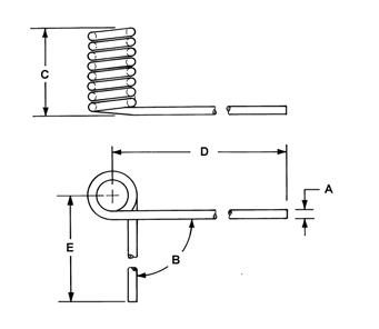
Model REAR ARM (See Illustration Below) Wire Diameter (A) Angle (B) Coil Width (C) Coils Length (D)
Lynx 2000 Bearcat 2000/Lynx 2000 LT .405" 85° 3.65" 6.75 18.50” .405" 70° 4.00" 6.75 18.50”
Bearcat XT .437" 75° 4.50" 7.75 18.50”
0730-218 SHOCK ABSORBERS Below is a list of shock absorbers used on the front and rear suspensions of Arctic Cat snowmobiles. If replacing a shock absorber, always select a shock absorber with the same length, both collapsed and extended.
SKI SHOCK Model Collapsed Length Extended Length Stroke Bearcat 2000/Lynx Models 11.55” 17.50” 5.95” Bearcat XT 10.67” 16.00” 5.33” FRONT ARM SHOCK
Model Collapsed Length Extended Length Stroke
Bearcat XT 8.42” 12.49” 4.07” Bearcat 2000/Lynx 2000 LT 8.09” 11.78” 3.69” Lynx 2000 8.48” 12.53” 4.05” REAR ARM SHOCK Model Collapsed Length Extended Length Stroke Bearcat 2000/Lynx 2000 LT 10.90” 16.69” 5.78” Bearcat XT 10.89” 16.67” 5.78” Lynx 2000 9.92” 15.00” 4.57”
NOTE: Torque specifications have the following tolerances:
Torque (ft-lb)
0-15 16-39 40+ Tolerance
±20% ±15% ±10%
DRIVE SYSTEM
Item Secured to Torque ft-lb
Drive Clutch ***
Engine Drive Clutch Cover Movable Sheave Cam Arm Pin Lock Nut Cam Arm Pin Cam Arm Set Screw* Cam Arm Drive Clutch* Driven Clutch Ring Gear Input Shaft Movable Sheave Torque Bracket Gear Case Chassis Gear Case Cover Gear Case Gear Case Drain/Fill Plug Gear Case Shift Actuator Gear Case
Output Shaft Brake Disc Driveshaft Driveshaft
Brake Caliper
Chassis Brakeline Caliper Brakeline Master Cylinder Speedometer Sensor BracketBrake Caliper STEERING/FRONT SUSPENSION/CHASSIS
51 120 in.-lb 11 19 in.-lb 22 32 72 in.-lb 20 12.5 15 41 in.-lb 70 120 20 10.5 21 17
Ski Ski Spindle Wearbar
32 108 in.-lb
Ski Ski Handle 54 in.-lb Shock Mount Frame Suspension Mounting Bracket 96 in.-lb Steering Post* Suspension Mounting Bracket 35 Steering Tie Rod Steering Post Arm 35 Tie Rod Spindle 30 Steering Arm Suspension Mounting Bracket 20 Drag Link** Steering Arm 12 Tie Rod Drag Link 35 Tie Rod End Drag Link 35 A-Arm Suspension Mounting Bracket 32 A-Arm (Upper) Spindle 32 Lower A-Arm Retainer** Spindle 13 Spindle Arm** Spindle 30 Sway Bar Mounting Bracket Suspension Mounting Bracket 120 in.-lb Shock Absorber Shock Mounting Frame 32 Upper Bearing Bracket Support Plate 96 in.-lb Shock Absorber Spindle 32 Rear Bumper Chassis 96 in.-lb Rear Rack (BC XT) Tunnel 20 Front Bumper (BC XT) Suspension Mounting Bracket 32 Front Bumper (BC XT) Shock Mounting Bracket 120 in.-lb
* w/Green Loctite #609 ** w/Blue Loctite #243 *** w/Oil
Wear Strip End Cap Mounting Block Rear Arm Item Secured to Torque ft-lb
Rail 50 in.-lb Rail 80 in.-lb
Rail 20
Rail 40
Front Arm Skid Frame Limiter Strap Spring Slide Rear Arm Limiter** Offset Arm Rail 40
Tunnel 40 Rail Support 72 in.-lb Rail 20
Rail 40
Idler Arm 20
Rail Support Rear Arm Rail 20
Idler Arm 40
Rear Shock (XT) Shock Pivot 40
Front Shock (XT) Rear Shock (XT) Articulating Skid Frame (XT) Shock Bracket (XT) Slide Block (XT) Shock Pivot (XT) Shock Bracket 40 Idler Arm 40 Rail 20
Front Arm 40 Rail Rail 20 40
Rear Axle (BC 2000/Lynx Models) Rail 20 Limiter Strap (BC 2000/Lynx Models) Front Arm 72 in.-lb Shock Pivot (Lynx 2000) Front Arm 20 Front Shock Axle (BC 2000/Lynx Models) Rail 40 Adjuster Bracket (BC 2000/Lynx Models) Rail 120 in.-lb Mounting Block (Lynx 2000) Idler Arm 20 Idler Wheel (BC 2000/Lynx Models) Mounting Block 20 Shock Pivot (BC 2000/Lynx 2000 LT) Rail 20
Torque Conversions
ft-lb N-m ft-lb N-m ft-lb N-m ft-lb N-m 1 1.4 26 35.4 51 69.4 76 103.4 2 2.7 27 36.7 52 70.7 77 104.7 3 4.1 28 38.1 53 72.1 78 106.1 4 5.4 29 39.4 54 73.4 79 107.4 5 6.8 30 40.8 55 74.8 80 108.8 6 8.2 31 42.2 56 76.2 81 110.2 7 9.5 32 43.5 57 77.5 82 111.5 8 10.9 33 44.9 58 78.9 83 112.9 9 12.2 34 46.2 59 80.2 84 114.2 10 13.6 35 47.6 60 81.6 85 115.6 11 15 36 49 61 83 86 117 12 16.3 37 50.3 62 84.3 87 118.3 13 17.7 38 51.7 63 85.7 88 119.7 14 19 39 53 64 87 89 121 15 20.4 40 54.4 65 88.4 90 122.4 16 21.8 41 55.8 66 89.8 91 123.8 17 23.1 42 57.1 67 91.1 92 125.1 18 24.5 43 58.5 68 92.5 93 126.5 19 25.8 44 59.8 69 93.8 94 127.8 20 27.2 45 61.2 70 95.2 95 129.2 21 28.6 46 62.6 71 96.6 96 130.6 22 29.9 47 63.9 72 97.9 97 131.9 23 31.3 48 65.3 73 99.3 98 133.3 24 32.6 49 66.6 74 100.6 99 134.6 25 34 50 68 75 102 100 136