20 minute read
Engine-Related Items

NOTE: Whenever a part is worn excessively, cracked, or damaged in any way, replacement is necessary.
SPECIAL TOOLS A number of special tools must be available to the technician when servicing the engine-related items.
Description p/n
Blind-Hole Bearing Puller Coolant Cap 0644-500 0644-156
Drive Clutch Spanner Wrench 0644-136
Valve and Spring Retainer Tool
0644-448 Fan Spanner Wrench 0644-340 Water Pump Bearing and Seal Tool Kit 0644-557 Oil Seal Protector Tool 0644-219 Engine Leak-Down Test Kit 0644-522 Vacuum Test Pump 0644-131 Hood Harness Extension 1686-659 Hood Harness Extension 1686-660 Oil Filter Wrench 0644-551
NOTE: Special tools are available from the Arctic Cat Service Parts Department.
Water Pump (5000)
REMOVING
! WARNING
When servicing the water pump, disconnect the negative battery cable to avoid injury. 1. Drain the engine coolant (see the appropriate Liquid
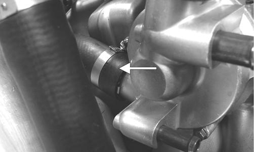
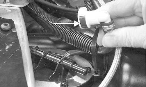
Cooling System in this section). 2. Remove the water bypass hose (A); then remove the coolant tank/engine hose (B).
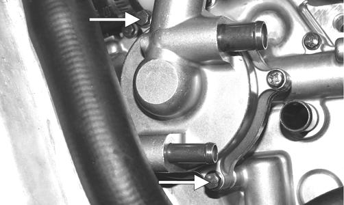
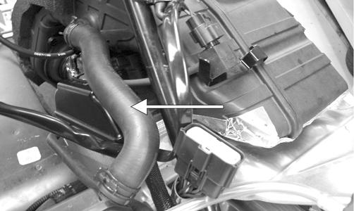
ZJ112A 3. Remove the separator tank breather hose to gain access to the water pump; then remove the water inlet hose from the water pump.
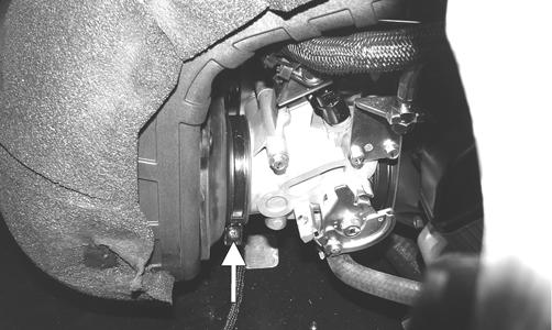
ZJ113A 4. Remove the two cap screws securing the water pump to the engine; then remove the pump and account for the O-ring.
ZJ114A
DISASSEMBLING/ASSEMBLING
0742-104 1. Secure the water pump in a suitable support device; then remove the two Phillips-head screws (A) securing the inner/outer pump housings. 2. Separate the inner/outer pump housings; then remove the E-clip (B) from the impeller shaft, remove the shaft from the inner housing, and remove the ceramic seal (C) from the shaft. 3. With the inner housing secured in a suitable clamping device and using Blind-Hole Bearing Puller, remove the mechanical seal (D); then remove the oil seal (E).
CAUTION
Do not apply excessive heat to the housing or the bushing next to the bearing may be damaged.
4. Using the bearing puller, remove the bearing (F) from the inner housing. NOTE: Apply heat to the housing to aid in removing the bearing.
CAUTION
Do not apply excessive heat to the housing or the bushing next to the bearing may be damaged.
5. Clean the inner and outer housings with parts-cleaning solvent; then dry with compressed air. ! WARNING
Always wear safety glasses when drying components with compressed air.
NOTE: For assembly, use Water Pump Bearing and Seal Tool Kit.
6. Using the appropriate-sized installation tool, install the bearing (F) into the inner housing. 7. Using the appropriate-sized installation tool, install the oil seal (E) with the spring side facing the bearing. 8. Place the mechanical seal (D) into the inner housing; then using the appropriate-sized installation tool, drive the seal into the housing until the lip of the seal is properly seated. 9. Install the ceramic seal (C) onto the impeller shaft with the ceramic face of the seal facing away from the impeller. 10. Install the impeller shaft into the inner housing and secure with the E-clip (B); then with a new O-ring properly positioned in the outer housing, place the water pump halves together. NOTE: Apply a light coat of grease on the O-ring to aid in keeping it properly positioned.
11. Secure the housings with the two Phillips-head screws (A); then tighten the screws with an impact driver.
INSTALLING 1. With a new O-ring (A) in place on the inner housing and the water pump shaft (B) properly aligned with the oil-feed pump shaft, install the water pump.
CAUTION
Care should be taken not to over-tighten the screws with the impact driver or damage to the housings may occur.

ZJ123A 2. With the water pump properly positioned, secure the pump with two cap screws and tighten to 84 in.-lb. 3. Install the water inlet hose and secure with the clamp; then install the separator tank breather hose and the remaining coolant hoses. Secure with the clamps. 4. Fill the cooling system (see appropriate Liquid Cooling System in this section).
Pressure Testing Engine
NOTE: To pressure test the engine, use Engine Leak-Down Test Kit.
Checking Compression (5000)
NOTE: Prior to this test procedure, verify the battery is fully charged and the console is positioned over the support bracket with the hood/main harness plugged in.
NOTE: This test must be done with the engine at operating temperature and “full-cranking RPM” and the decompression system active.
With the spark plugs removed, install the compression tester gauge with adapter into the spark plug hole; then with the throttle valve in the full-open position, crank the engine over to get the psi reading. Compression should be 120 psi.
CAUTION
Do not ground the spark plug on the cylinder head cover. The cover is made of magnesium and any contact with spark or electrical arc will severely pit the surface.
NOTE: Verify both cylinder compression readings are within 10% of each other.
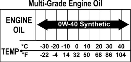
Changing Oil/Filter (5000)
1. Using a putty knife, remove the belly pan plug.
2. Park the snowmobile on a level surface; then start the engine and allow it to warm up for 10-15 minutes, or if the snowmobile was operated, allow engine to idle for approximately 30 seconds. 3. Shut the engine off; then place drain pans beneath both engine oil drain plugs (crankcase and oil reservoir).
! WARNING
Care must be taken if a hot drain plug is removed by hand. Burning could occur.
ZJ003A 4. Remove the drain plugs and allow the oil to drain completely. Remove the strainer from the oil reservoir to allow the oil to drain completely. 5. Install the oil strainer, drain plugs, and new washers and tighten to 15 ft-lb. 6. Install a new belly pan plug. 7. Using Oil Filter Wrench, loosen (but do not remove) the oil filter and allow the oil to drain from the filter; then remove the filter. 8. Apply a light coat of fresh engine oil to the seal of the new oil filter. 9. Install the new oil filter by turning the oil filter by hand until the seal has contacted the oil filter mounting surface; then tighten the oil filter to 15 ft-lb. 10. Pour 2.9 l (3 U.S. qt) of the recommended engine oil into the oil reservoir. 11. Open the air bleed bolt located on the oil pump (beneath the coolant tank) to purge air from the oil hose.
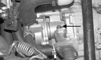
ZJ004A 12. Without starting the engine, place the handlebar emergency stop switch to the RUN position and the ignition switch to the ON position. The Oil Pressure
Warning Light should illuminate. 13. If the warning light illuminates (from step 12), start the engine. The warning light should go out within five seconds. If it does, proceed to step 14. NOTE: If the warning light does not go out, shut the engine off immediately and repeat step 11; then place the ignition switch to the ON position and repeat step 13.
14. Shut the engine off and pour the remaining amount (0.9 l or 1 U.S. qt) of recommended oil into the oil reservoir; then proceed to check the oil level to verify and finalize the procedure.
Testing Oil Pressure (5000)
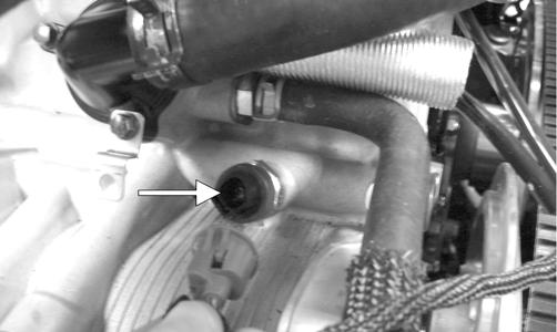
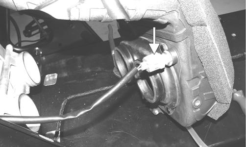
The Low Oil Pressure Warning Light indicates engine oil pressure, not the oil level; however, if the oil level is low, it may affect oil pressure. The light should illuminate each time the ignition switch is turned to RUN or START, and it should go out when the engine starts. If the light stays illuminated or it illuminates while the engine is running, oil pressure has been lost and the engine will automatically shut off. If oil pressure is lost, first verify oil level is correct. After adding oil, oil pressure should be normal. If not proceed to step 1. 1. Locate the oil pressure sensor below the thermostat coolant hose; then disconnect the plug-in connector from the sensor.
ZJ128B
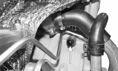
2. Using a 24 mm wrench, remove the oil pressure sensor from the engine. 3. Using an oil pressure gauge and adapter, thread the adapter into the oil pressure sensor hole and tighten securely. 4. Start the engine, run at 4000 RPM, and observe the oil pressure. The engine oil pressure specification is 29 psi ± 20%. NOTE: This test must be done with the engine at running temperature.
5. After verifying oil pressure, remove the adapter and gauge from the engine, install the sensor, and tighten to 120 in.-lb. Start the engine and check for oil leaks. NOTE: Before installing the sensor, it may be necessary to apply thread sealant or teflon tape to the sensor threads.
CAUTION
Take care not to allow thread sealant or teflon tape into the oil passage or severe engine damage will occur.
Oil Flow Chart (5000)
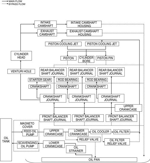
SNO2170
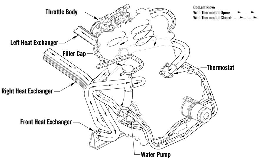
Liquid Cooling System (5000)
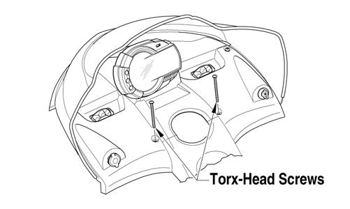
The liquid cooling system consists of a heat exchanger, water pump, and thermostat. The system should be inspected for leaks or damage whenever an overheating problem is experienced. DRAINING COOLING SYSTEM 1. Open the right-side access panel. 2. Remove the hardware securing the exhaust resonator; then remove the resonator. 3. Remove the hose clamp from the coolant hose connecting the water pump to the right side of the oil cooler. Clamp off the coolant hose; then with a drain pan positioned under the coolant hose, remove the hose from the water pump and tip the hose downward allowing the coolant to drain completely. 4. Apply 5-8 psi to the coolant system through the coolant overflow tube and continue until the coolant stops draining from the system. FILLING/BLEEDING COOLING SYSTEM 1. Remove the left- and right-side access panels and hood; then remove the torx-head screws securing the console. 2. Move the console up and forward; then with the harness connected, securely position the console on the snowmobile.
3. On the Bearcat, remove the headlight support bracket/heat shield. 4. Loosen the bleed screw and add coolant into the filler neck until coolant is visible at the bleed screw; then tighten the bleed screw and add coolant to the coolant reservoir Full-Cold line.
CAUTION
Use care not to allow the console harness to come into contact with the exhaust pipe during this procedure.
CAUTION
The cooling system must be properly filled. If the system isn’t properly filled, engine damage will occur.
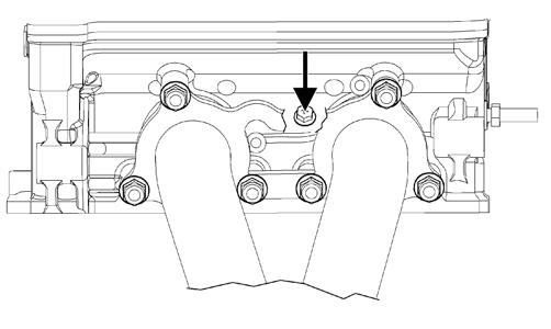
744-032A 5. Start the engine and allow it to run for five minutes. 6. With the engine cool, loosen the bleed screw and allow the coolant level in the filler neck to drop; then with the bleed screw loose, add coolant into the filler neck until no air is visible or heard at the bleed screw. Tighten the bleed screw and add coolant to the reservoir if necessary.
NOTE: If the coolant level in the filler neck suddenly drops when the bleed screw is loosened, an air-lock occurred in the cylinder head. Add coolant to the filler neck until full before starting the engine.
CAUTION
Running the engine with low coolant level can cause severe engine damage.
7. Start the engine and allow it to run for five minutes; then shut the engine off and allow it to cool. 8. Repeat steps 6-7 at least two more times (more if necessary) until no air is in the cooling system.
9. On the Bearcat, install the headlight support bracket/ heat shield. 10. Secure the console using the existing torx-head screws and install the hood and side panels. INSPECTING COOLANT HOSES AND CLAMPS All coolant hoses and connections should be checked annually for deterioration, cracks, and wear. All coolant hoses and clamps should be replaced every four years. INSPECTING THERMOSTAT 1. Inspect the thermostat for corrosion, wear, or spring damage. 2. Using the following procedure, inspect the thermostat for proper operation.
A.Suspend the thermostat in a container filled with water; then heat the water and monitor the temperature with a thermometer.
B.The thermostat should open at 75° C (167° F). Once the thermostat starts to open, and allow it to cool down verifying it has returned to the fully closed position.
CAUTION
Operating the snowmobile with air in the cooling system will cause severe damage to the engine.
Bearcat 5000 CAUTION
Never heat the thermostat to the fully open position or damage to the thermostat may occur.
Cooling System Schematics
The following schematics are representative of the different styles of cooling systems in the Arctic Cat snowmobiles. Some components may vary from model to model; therefore, the technician should use discretion and sound judgment when servicing a particular cooling system.
0744-065
Bearcat XT GS

0747-908
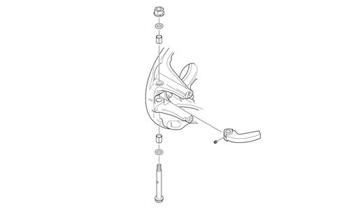
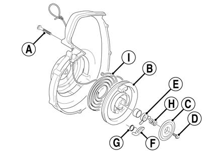
Recoil Starter (2000)
KEY
A. Cap Screw
B. Roller
C. Friction Plate
D. Cap Screw
E. Pawl Activator
F. Pawl
G. Return Spring
H. Friction Plate Spring
I. Main Spring
743-711A
REMOVING 1. Tie a slip-knot in the starter rope below the console and allow the rope to slowly retract against the starter case. 2. Remove the knot at the handle, remove the handle, and account for the handle cap; then thread the rope through the bushing in the console. 3. Remove the cap screws (A) securing the starter assembly to the magneto case; then remove the starter assembly. DISASSEMBLING
1. Secure the recoil starter in a vise.
2. Rotate the roller (B) counterclockwise until the notch of the roller is near the rope guide in the case. Guide the rope into the notch and slowly allow the roller to retract until all recoil spring tension is released. 3. While exerting downward pressure on the friction plate (C), remove the cap screw (D). 4. Slowly release the friction plate and lift the plate with pawl activator (E) free of the recoil roller; then remove the pawl activator from the friction plate. 5. Remove the pawl (F) and the return spring (G); then remove the friction plate spring (H). 6. Carefully lift the roller free of the case making sure the main spring (I) does not disengage from the case.
Account for the bushing.
7. Remove the main spring from the case by lifting the spring end up and out. Hold the remainder of the spring with thumbs and alternately release each thumb to allow the spring to gradually release from the case.
! WARNING
Always wear safety glasses and gloves when servicing the recoil starter.
! WARNING
During the disassembly procedure, continuous downward pressure must be exerted on the reel so it does not accidentally disengage and cause injury. Care must be taken when allowing the recoil roller to unwind. Make sure all spring tension is released before continuing.
! WARNING
Care must be taken when lifting the roller free of the case.
NOTE: Do not remove the main spring unless replacement is necessary. It should be visually inspected in place to save time.
8. Unwind the rope from the roller, untie the slip-knot, and remove the rope. CLEANING AND INSPECTING 1. Clean all recoil starter components. 2. Inspect springs and pawl for wear or damage. 3. Inspect the roller and case for cracks or damage. 4. Inspect the center hub for wear, cracks, or damage. 5. Inspect the rope for breaks or fraying. 6. Inspect the main spring for cracks, crystallization, or abnormal bends. 7. Inspect the handle for damage, cracks, or deterioration. ASSEMBLING 1. Hook the end of the main spring around the mounting lug in the case. 2. Insert the main spring into the case; then wind it in a counterclockwise direction until the complete spring is installed.
NOTE: The main spring must seat evenly in the recoil case.
3. Insert the rope through the hole in the roller and tie a knot in the end; then wrap the rope counterclockwise around the roller leaving approximately 20 in. of rope free of the roller.
4. Apply low-temperature grease to the main spring and hub. 5. Align the hook in the end of the main spring with the notch in the roller. 6. Carefully slide the roller over the hub and engage the spring with the roller; then install the bushing. 7. Install the return spring making sure the short leg of the spring is properly installed in the hole in the roller; then install the pawl making sure the return spring is properly positioned in the notch of the pawl. 8. Slide the end of the rope through the rope guide of the case; then tie a slip-knot in the rope. 9. Apply a low-temperature grease to the friction plate.
Place the pawl activator into position on the friction plate making sure the arms of the activator are properly positioned to the pawl. 10. Place the friction plate into position allowing it to rest on the friction plate spring; then install the cap screw (coated with blue Loctite #243) and thread the cap screw in until it contacts the friction plate. 11. Press down on the friction plate and tighten the cap screw to 48 in.-lb. 12. With 20 in. of rope exposed, hook the rope in the notch of the roller. 13. Rotate the roller four or five turns counter-clockwise; then release the rope from the notch and allow the rope to retract. 14. Pull the rope out two or three times to check for correct tension.
NOTE: Increasing the rotations in step 13 will increase spring tension.
INSTALLING 1. Place the starter assembly into position against the magneto case. 2. Secure the starter with cap screws (coated with blue
Loctite #243). Tighten to 60 in.-lb. NOTE: Before tightening the cap screws, slowly pull the recoil rope until the pawl engages; then tighten the cap screws centering the recoil against the magneto case.
3. Thread the rope through the bushing in the console; then install the handle and secure with a knot. Seat the cap. 4. Release the slip-knot in the rope.
Air Silencer
2000 The air silencer is a specially designed component used to silence the incoming fresh air and also to catch the fuel that “spits back” out of the carburetors. The carburetors are calibrated with the air silencer in position; therefore, the engine must never be run with the air silencer removed. Cleaning and Inspecting 1. Check for holes or cracks in the silencer. 2. Periodically clean the silencer by removing the cover/tool tray assembly and vacuuming the interior of the silencer. 5000
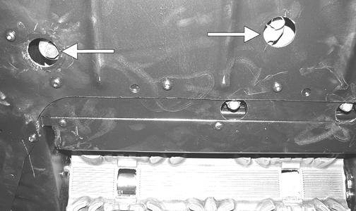
Removing/Inspecting/Cleaning 1. Remove the two torx-head cap screws (A) securing the console to the chassis; then lift up the rearward end of the console and disconnect the console harness plug-in. Remove the console.
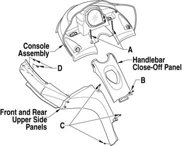
741-744A 2. Remove the torx-head cap screws securing the upper front/rear panels (C) and the handlebar close-off panel (B) along with the body screws securing the knee-pads to the steering support. 3. Remove the torx-head cap screws (D) securing the upper front panel to the front bumper. 4. Remove the four cap screws securing the upper bearing bracket to the upper support plate.
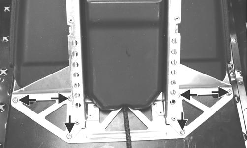
ZJ097A 5. Remove the four cap screws securing the support plate to the steering support.
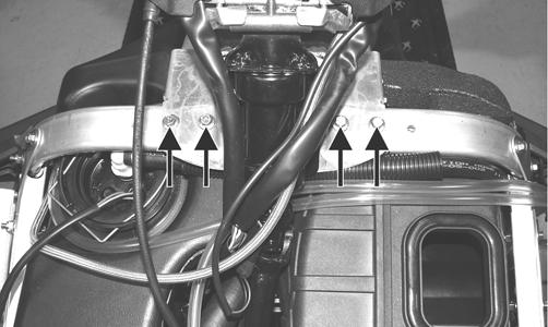
ZJ009A 6. Remove the six torx-head screws securing the seat support assembly to the tunnel; then slide the support back out of the way.
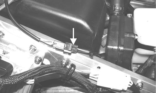
ZJ010A 7. Disconnect the fuel pump four-wire connector; then slide the gas tank rearward enough to gain access to the gasline hose connector.
ZJ011A 8. Compress the clip on the gasline hose connector and remove the hose from the gas tank; then disconnect the vent hose and remove the gas tank.
IO053A
! WARNING
The gasoline supply hose may be under pressure. Place an absorbent towel around the connection to absorb gasoline; then remove the hose slowly to release the pressure.
NOTE: After the gas tank vent hose has been removed, plug the hose outlet of the gas tank to avoid gas leakage.
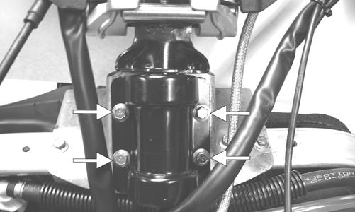
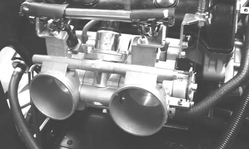
9. Remove the two torx-head cap screws securing the air silencer to the chassis; then loosen the screws on the clamps securing intake boot to the throttle bodies.
ZJ013A 10. Remove the breather hose from the air silencer.
ZJ096B 11. Move the air silencer far enough to the right to bypass the air silencer mounting bracket; then slide the air silencer rearward and disconnect the air temperature sensor. Remove the air silencer from the chassis.
ZJ015A 12. Inspect the throttle valve thoroughly for carbon residue buildup. If signs of carbon buildup exist, the throttle body should be cleaned (see Fuel System (EFI) -
Throttle Body Assembly in Fuel Systems section).
ZJ125 13. Remove the air temperature sensor from the air silencer.
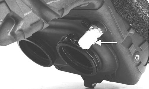
ZJ126A 14. Split the protective foil at the seam of the air silencer; then remove the retaining clips securing the dual intake boot to the air silencer. 15. Remove the seven machine screws and separate the air silencer halves. 16. Inspect the air silencer thoroughly for any foreign material; then clean the air silencer with soap and water. Dry the air silencer thoroughly prior to installing. Installing 1. Join the air silencer halves and secure with the seven machine screws; then install the dual intake boot and secure with retaining clips. 2. Install the air temperature sensor. NOTE: Before installing the air silencer, make sure the gasline hose is routed over the air silencer.
3. Connect the air temperature sensor harness plug into the sensor on the air silencer; then with screws of the flange clamps directed properly as noted during removing, install the air silencer and secure to the chassis with the two torx-head cap screws. Secure the flange clamps to the throttle body. NOTE: To aid in installing the air silencer, apply a coat of alcohol on the insides of the intake boot openings.
NOTE: Install the air silencer at an angle positioning it to the PTO-side throttle body first and tightening its clamp; then working it back and forth and with an angle tool, slide the MAG-side air silencer boot onto the throttle body and tighten its clamp. Once in place and secured, carefully inspect that the boots are properly seated to the throttle bodies.
ZJ015A
ZJ013A 4. Install the breather hose connecting the air silencer to the separator tank; then connect the harness plug to the sensor.
ZJ096B
NOTE: Before placing the gas tank into position on the chassis, install the gasline hose to the tank, push down on the connector until it snaps into place, and route the vent hose to its proper position as noted during removing.

IO054A
CAUTION
Make sure the gasline hose is properly locked to the gas tank before continuing installing. 5. Install the gas tank to its proper position; then secure the gas tank with the seat support assembly and install the six torx-head cap screws. Tighten securely.
ZJ010A 6. Install the four cap screws securing the steering support plate to the steering support.
ZJ009A 7. Install the four cap screws securing the upper bearing bracket to the upper support plate and tighten to 8 ft-lb.
ZJ097A 8. Connect the fuel pump four-wire connector; then secure the knee-pads to the steering support with the two body screws. 9. Install the upper body panels and secure with the torxhead cap screws; then install the handlebar close-off panel and secure it with two torx-head cap screws. 10. Place the console into position on the headlight support bracket; then connect the console harness connector.

ZJ098A 11. Secure the console to the chassis with the two torxhead cap screws. 12. Install the seat.