11 minute read
Fuel/Lubrication/Cooling

SPECIAL TOOLS A number of special tools must be available to the technician when performing service procedures in this section.
Tachometer Description
Oil Pressure Test Kit p/n
0644-275
0644-495
NOTE: Special tools are available from the Arctic Cat Service Department.
Diesel Fuel Injection System
The diesel engine in this Arctic Cat ATV is a “compression ignition” engine. Extremely high pressure in the combustion chamber raises air temperature high enough to cause ignition of the fuel upon injection into the combustion chamber. No spark is present or required for ignition. In this style of engine, diesel fuel is drawn from the fuel tank by a low pressure lift pump. From the lift pump, fuel is pumped through the fuel filter/fuel shut-off and delivered to the fuel rail. Low pressure fuel at 0.42-0.56 kgcm2 (6-8 psi) flows to the unit injectors (high pressure fuel pump/fuel injector) where the fuel pump, driven by a special lobe on the camshaft, increases the fuel pressure to 143-153 kg-cm2 (2030-2175 psi). At this point, the fuel is atomized by the fuel injector nozzle as it enters the combustion chamber. Fuel in excess of the amount required for any particular power setting is directed back into the fuel return side of the fuel rail and routed back to the fuel filter head where it either recirculates or is returned to the fuel tank via the fuel return hose. Fuel flow is shut off when the ignition switch is turned to the OFF position. A fuel solenoid valve is located on the fuel filter head and opens the valve whenever a 12 DC volt current is applied to the solenoid.
Lift Pump
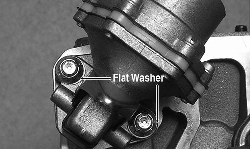
REMOVING 1. Remove the banjo-fitting bolts securing the fuel hoses to the lift pump; then remove the two nuts securing the lift pump to the cylinder head. Account for four crush washers, an O-ring, and two flat washers.
DE078B
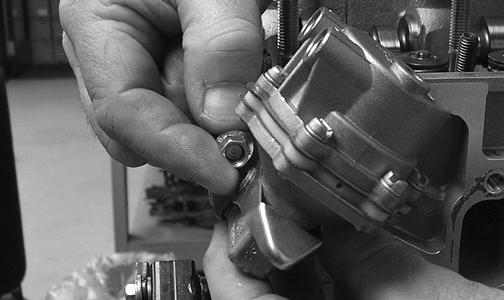
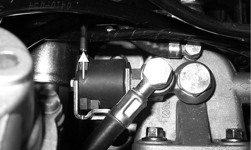
DE309A 2. While holding pressure against the lift pump push rod, rotate the engine until the push rod is fully retracted.
NOTE: If pressure is not applied to the push rod while rotating the engine, the push rod may become dislodged from the eccentric ring requiring valve cover removal to relocate.
INSTALLING 1. Using a new O-ring, place the fuel pump onto the cylinder head and secure with the existing hardware.
Tighten the nuts alternately until the fuel pump is seated against the head; then tighten securely.
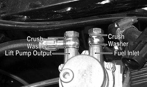
DE530 2. Connect the fuel inlet and lift pump outlet hoses to the fuel lift pump using new crush washers and secure with the banjo-fitting bolts. Tighten securely.
DE078A
Unit Injectors
To service the unit injectors, see Top-Side Components in Engine/Transmission.
Injector Timing
NOTE: For injector timing instructions, see TopSide Components in Engine/Transmission.
Fuel Filter
To replace the fuel filter, see Periodic Maintenance/TuneUp.
Fuel Solenoid Assembly
NOTE: After troubleshooting the fuel solenoid (see Electrical System) if it is determined that replacement is necessary, use the following procedure. REMOVING 1. Remove the right-front inner splash panel; then remove the V-belt cooling boot from the V-belt housing. 2. Locate the fuel solenoid mounted on top of the fuel filter head; then disconnect the spade connector from the solenoid.
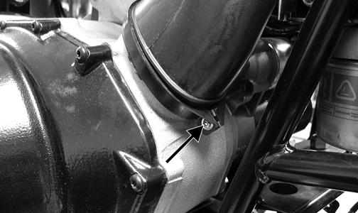
DE647B 3. Remove the banjo-fitting bolts (A) and (B) and remove the fuel solenoid. Account for four crush washers.

DE647A
INSTALLING 1. Using new crush washers, secure the fuel solenoid to the filter housing with banjo-fitting bolt (B) and tighten securely.
DE647A 2. Secure the fuel hose to the fuel solenoid with new crush washers and banjo-fitting bolt (A). 3. Connect the spade connector to the solenoid.
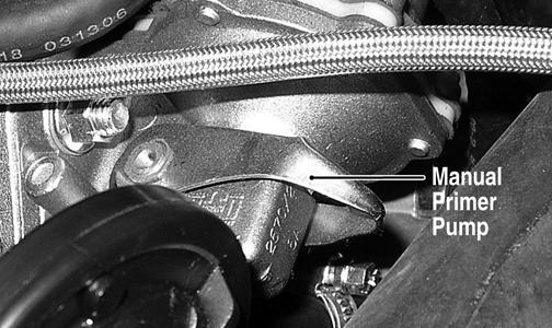
DE647B 4. Bleed any air from the system by turning the ignition switch to the ON position and pumping the manual primer pump until resistance is felt.
DE031A 5. Start the engine and check for leaks; then shut off the engine and install the inner fender splash panel, right-side engine cover, and seat. Make sure the seat latches securely.
Fuel Tank
! WARNING
Whenever any maintenance or inspection is made on the fuel system during which there may be fuel leakage, there should be no welding, smoking, open flames, etc., in the area. REMOVING
NOTE: Fuel tank removal should only be necessary if the tank is leaking fuel or has been contaminated with water, dirt, or inadvertently filled with gasoline. 1. Remove the seat. 2. Remove the rear rack and fenders (see Steering/
Frame/Controls). 3. Disconnect the hose from the fuel tank to the lift pump; then disconnect the vent hose and fuel return hose. 4. Remove the cap screws securing the gas tank to the frame. 5. Disconnect the fuel gauge connector; then remove the fuel tank. CLEANING AND INSPECTING 1. Remove the fuel level sensor and fuel pick-up screen. Account for a seal. 2. Completely drain all contaminated fuel from the fuel tank; then thoroughly wash the tank out with hot, soapy water. 3. Dry the tank interior with compressed air. NOTE: Repeat steps 2 and 3 until all contaminants are removed.
4. Back-flush the fuel screen with hot, soapy water and dry with compressed air. NOTE: If any “pin-holes” are noted in the fuel screen, replace the fuel level sensor assembly. 5. Inspect the tank cap and filler neck for chipped or broken threads. 6. Inspect the fuel tank mountings for security, signs of cracking, or wearing through the tank. 7. Inspect all fuel and vent hoses for cracks, softening, or deterioration. Replace as required. INSTALLING 1. Place the fuel tank into position in the frame; then install the cap screws. Tighten securely. 2. Connect the fuel hose from the lift pump; then connect the fuel gauge connector. 3. Install the vent hose and fuel return hose; then fill the fuel tank with clean diesel fuel. 4. Replace the fuel filter (see Periodic Maintenance/
Tune-Up). 5. Pump the manual primer pump 12-20 strokes; then start the engine and inspect for leakage. 6. Install the rear fenders and rack (see Steering/Frame/
Controls); then install the seat making sure it latches securely.
Fuel/Vent Hoses
Replace the fuel hoses every two years. Damage from aging may not always be visible. Do not bend or obstruct the routing of the vent hose or fuel return hose.
Oil Filter/Oil Pump
NOTE: Whenever internal engine components wear excessively or break and whenever oil is contaminated, the oil pump should be replaced. The oil pump is not a serviceable component.
Testing Oil Pump Pressure
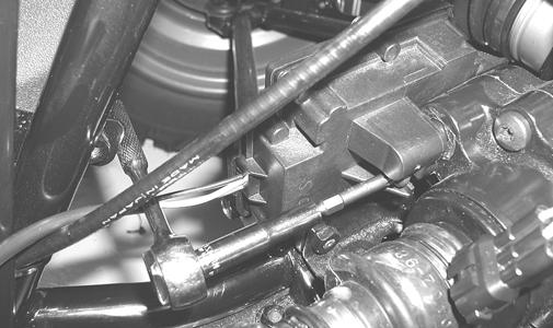
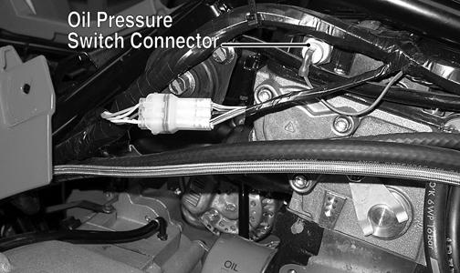
NOTE: The engine must be warmed up to the specified temperature for this test (see General Information). 1. Connect the Tachometer to the engine. 2. Disconnect the oil pressure switch connector; then connect the Oil Pressure Test Kit to the oil pressure switch port.
DE077B
NOTE: Some oil see page may occur when installing the oil pressure gauge. Wipe up oil residue with a cloth.
3. Start the engine and run at the recommended RPM.
The oil pressure gauge must read as specified (see
Engine/Transmission - Specifications). NOTE: If oil pressure is lower than specified, check for an oil leak, damaged oil seal, defective oil pump, or oil cooler.
NOTE: If oil pressure is higher than specified, check for too heavy engine oil weight (see General Information - Fuel - Oil - Lubricant), clogged oil passage, clogged oil filter, or improper installation of the oil filter.
Liquid Cooling System
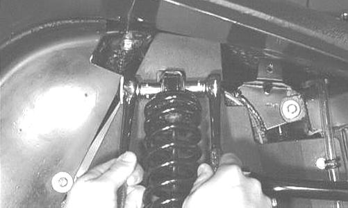
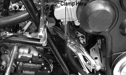
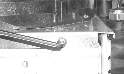
To check the cooling system, see Periodic Maintenance/ Tune-Up. DRAINING COOLANT The cooling system does not have a drain; therefore, coolant must be removed using the following procedure. 1. Using suitable in-line clamps, close off the lower radiator hose and the coolant bypass hose next to the water pump.
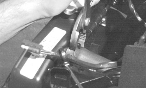
DE510A 2. Place a suitable drain pan with a capacity of at least 4 l (4.2 U.S. qt) under the left front of the engine; then loosen the hose clamp on the coolant bypass hose. 3. Remove the hose and allow coolant to drain into the drain pan. A funnel or short hose can be used to direct coolant into the drain pan. 4. Install the coolant bypass hose and tighten the clamp securely; then remove the in-line clamps. FILLING COOLANT 1. Elevate the rear of the ATV approximately 30 cm (12 in.) and secure in place using appropriate blocks.
2. Remove the cap from the filler neck (located under the service access cover) and slowly pour the recommended amount of coolant into the system. 3. Move the ATV outside or to a well-ventilated area and start the engine allowing it to run for several minutes; then remove the filler cap and check the coolant level. Add coolant as required until coolant is visible within one inch of the top of the filler neck. 4. Install the filler cap on the filler neck and tighten until the cap contacts the stop.
CAUTION
Failure to elevate the rear of the ATV may result in air being trapped in the cooling system causing severe engine damage due to overheating.
! WARNING
Do not over-tighten coolant filler cap or excess pressure will build up in the cooling system causing cooling system damage and possible bodily harm.
Radiator
REMOVING 1. Drain the coolant at the engine. 2. Remove the front rack (see Steering/Frame/Controls). 3. Remove the front bumper and front fender panel (see
Steering/Frame/Controls). 4. Remove the upper and lower coolant hoses.
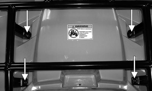
5. Remove the cap screws and nuts securing the radiator to the frame. 6. Disconnect the fan wiring from the main wiring harness; then remove the radiator/fan assembly and account for the grommets and collars. 7. Remove the fan/fan shroud assembly from the radiator.
CC863
CLEANING AND INSPECTING 1. Flush the radiator with water to remove any contaminants. 2. Inspect the radiator for leaks and damage. 3. Inspect all hoses for cracks and deterioration. 4. Inspect all fasteners and grommets for damage or wear. INSTALLING 1. Position the fan/fan shroud assembly on the radiator; then secure with existing hardware. 2. Place the radiator with grommets and collars into position on the frame; then install the cap screws and nuts. Tighten securely. 3. Install the upper and lower coolant hoses; then secure with hose clamps.
AF734D 4. Install the front bumper and front fender panel (see
Steering/Frame/Controls). 5. Install the front rack (see Steering/Frame/Controls). 6. Fill the cooling system with the recommended amount of antifreeze. Check for leakage.
Hoses/Thermostat
REMOVING 1. Drain approximately two quarts of coolant from the cooling system. 2. Remove the two cap screws securing the thermostat cover housing to the thermostat housing. Account for an O-ring and a thermostat. INSPECTING 1. Inspect the thermostat for corrosion, wear, or spring damage. 2. Using the following procedure, inspect the thermostat for proper operation.
A.Suspend the thermostat in a container filled with water.
B.Heat the water and monitor the temperature with a thermometer.
C.The thermostat should start to open at 80° C (176° F) and be fully open at 95° C (203° F).
D.If the thermostat does not open or remains open, it must be replaced. 3. Inspect all coolant hoses, connections, and clamps for deterioration, cracks, and wear. NOTE: All coolant hoses and clamps should be replaced every four years or 4000 miles. INSTALLING 1. Place the thermostat and O-ring into the thermostat housing; then secure the thermostat housing to the cylinder head with the two cap screws. 2. Install the crossover coolant hose onto the water pump and engine water inlet. Secure with the two hose clamps. 3. Slide the upper hose onto the thermostat housing and radiator. Secure with the two hose clamps. 4. Install the lower coolant hose onto the water pump housing and radiator. Secure with the two hose clamps. 5. Fill the cooling system with the recommended amount of antifreeze. Check for leakage.
Fan
REMOVING 1. Remove the radiator (see Radiator in this section). 2. Remove the fan assembly from the radiator.
INSTALLING 1. Position the fan assembly on the radiator; then secure with existing hardware. NOTE: The fan wiring must be in the upper-right position. 2. Install the radiator (see Radiator in this section).
Water Pump
NOTE: The water pump is a non serviceable component and must be replaced as an assembly. To replace the water pump, see Engine/Transmission Left-Side Components.
Troubleshooting
Problem: Starting impaired Condition Remedy 1. Fuel contaminated 1.Drain fuel tank and fill with clean fuel Problem: Idling or low speed impaired Condition Remedy 1. Fuel filter plugged 1.Replace fuel filter Problem: Medium or high speed impaired Condition Remedy 1. Governor spring broken 1.Replace speed governor spring 2. Fuel filter obstructed 2.Replace filter 3. Throttle cable out of adjustment 3.Adjust throttle cable