18 minute read
Steering Post/Tie Rods

3. Inspect threaded areas of all mounting bosses for stripping. 4. Inspect for missing decals. INSTALLING 1. Remove the gas tank cap and set the rear body panel in position; then install the cap and connect the taillight/brakelight connector. 2. Place the rear rack in position with four bushings and secure with four cap screws, shoulder screws, and flanged nuts. Tighten securely.
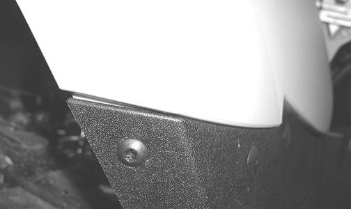
CD690A 3. Install one shoulder screw and three plastic rivets (on each side) to secure the front of the rear body panel to the footwells.
CD691
4. Connect the battery (positive cable first). 5. Secure the front and rear panels with two machine screws; then install the left and right side panels. NOTE: If the front body panel has not been installed, see Front Body Panel/Side Panels in this section.
6. Place the seat into position making sure it locks securely.
REMOVING 1. Remove the ignition switch retaining ring; then remove the reinstallable rivets securing the instrument pod to the mounting bracket and remove the pod.
CD759 2. Remove the reinstallable rivets securing the radiator access cover and remove the cover.

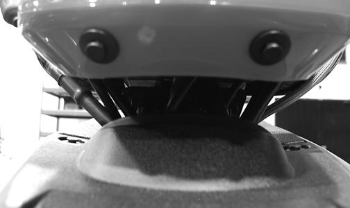
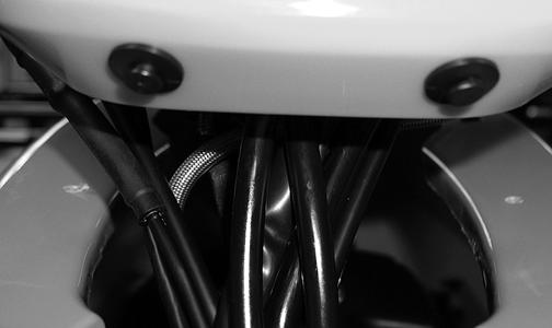
CD666 3. Remove the reinstallable rivets securing the steering post cover and remove the cover. 4. Unlatch the storage compartment lid; then slide the storage compartment cover assembly forward and lift off. 5. Remove the four cap screws securing the handlebar caps and instrument pod bracket to the steering post; then move the handlebar out of the way. Account for four handlebar caps. 6. Remove two cap screws securing the upper steering post bearing to the frame. Account for two bearings and two housings.
CD760
7. Using a suitable lift stand, raise the ATV enough to remove the front wheels; then remove the left-side and right-side splash panels.

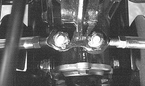
CD685 8. Remove the cotter pins and slotted nuts from the inner and outer tie rod ends; then remove the tie rods from the steering post arm and the left-side and rightside steering knuckles.
AF778D
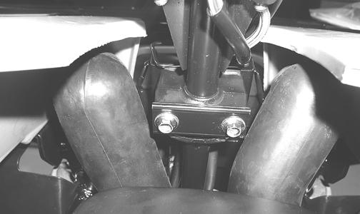
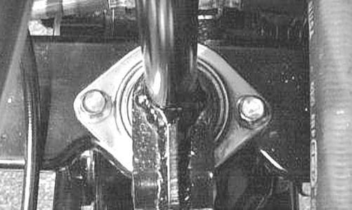
KX039 9. Remove two cap screws securing the lower steering post bearing flange to the frame; then remove the steering post.

AL600D
CLEANING AND INSPECTING 1. Wash the tie rod ends in parts-cleaning solvent. Dry with compressed air. Inspect the pivot area for wear.
Apply a low-temperature grease to the ends.
2. Inspect the tie rods for damaged threads or wear. 3. Inspect the tie rods for cracks or unusual bends. 4. Inspect all welded areas for cracks or deterioration. 5. Inspect the steering post and steering-post brackets for cracks, bends, or wear. 6. Inspect the bearing halves, bearing caps, and bearing housings for cracks or wear. 7. Inspect the handlebar tube for cracks, wear, or unusual bends. 8. Inspect the handlebar grips for damage or wear. INSTALLING 1. Place the steering post into position; then secure the lower bearing flange to the frame with two cap screws. Tighten to 20 ft-lb.
! WARNING
Always wear safety glasses when using compressed air.
AL600D 2. Place the upper steering post bearings into the housings; then position on the steering post and secure the housings to the frame with two cap screws. Tighten to 20 ft-lb.
CD760 3. Install the tie rods and secure with the slotted nuts.
Tighten to 35 ft-lb; then install new cotter pins. NOTE: If the slots do not align with the holes in the tie rod ends, tighten the nuts just enough to allow installation of the cotter pins.

AF778D 4. Install the splash panels; then install the front wheels and tighten to 45 ft-lb (steel wheels) or 80 ft-lb (aluminum wheels) using a crisscross pattern. 5. Lower the ATV and place the handlebar and caps into position on the steering post; then position the instrument pod mounts on top of the caps and secure with the four cap screws. Tighten to 20 ft-lb. 6. Place the instrument pod into position; then secure with reinstallable rivets and the ignition switch locking ring.
CD677 7. Install the steering post access cover and secure with reinstallable rivets; then install and secure the radiator access cover.
Handlebar Grip
REMOVING 1. Remove the plug and end-cap from the handlebar. 2. Using compressed air between the grip and the handlebar, twist the grip back and forth until it slides free of the handlebar. INSPECTING 1. Inspect the grip for wear, cuts, or cracks. 2. Inspect the grip for deterioration. INSTALLING NOTE: Before installing a grip, use contact spray or alcohol to clean the inside of the grip and the handlebar of glue residue, oil, or any other contaminant. 1. Apply a liberal amount of Handlebar Grip Adhesive to the inside of the grip. 2. Slide the grip onto the handlebar until it is fully seated with the smooth part of the grip facing up. 3. Wipe off any excess glue; then secure the grip with the handlebar plug and end-cap.
Hand Brake Lever/Master Cylinder Assembly
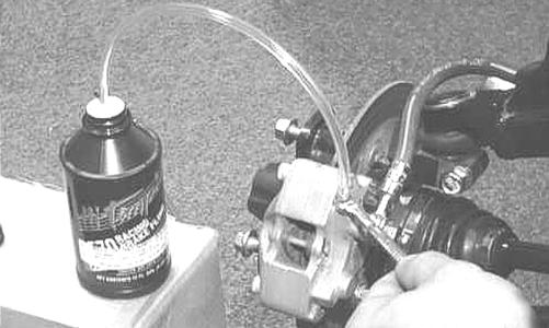
NOTE: The master cylinder is a non-serviceable component; it must be replaced as an assembly. REMOVING 1. Slide a piece of flexible tubing over one of the wheel bleeder valves and direct the other end into a container. Remove the reservoir cover; then open the bleeder valve. Allow the brake fluid to drain completely. NOTE: Compressing the brake lever several times will quicken the draining process.
AF637D
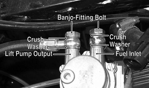
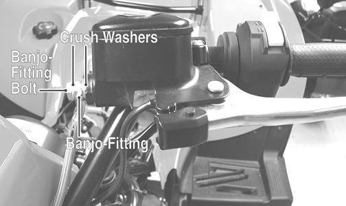
2. Place an absorbent towel around the connection to absorb brake fluid. Remove the banjo-fitting from the master cylinder. Account for two crush washers and a banjo-fitting bolt.
DE059A
CAUTION
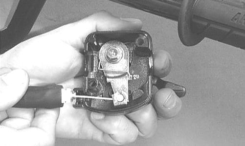
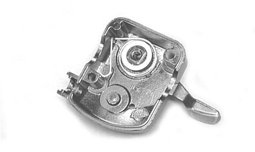
Brake fluid is highly corrosive. Do not spill brake fluid on any surface of the ATV. 3. Remove the snap ring and pivot pin securing the brake lever to the master cylinder housing; then remove the brake lever and set aside. 4. Dislodge the brakelight switch from the master cylinder housing by gently pressing it toward the pivot pin hole in the housing; then lay it aside leaving the switch and wiring harness connected.
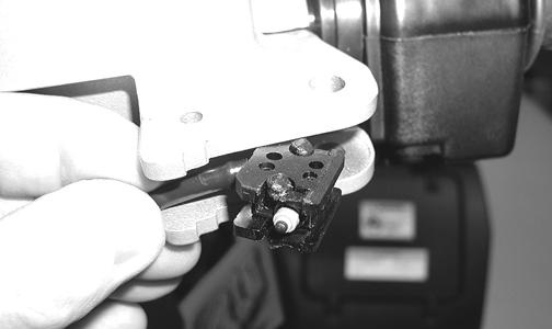
BC205 5. Remove the clamp screws securing the brake housing to the handlebar; then remove the assembly from the handlebar.
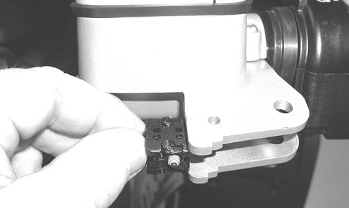
DE058A INSPECTING 1. Inspect the pin securing the brake lever for wear. 2. Inspect the brake lever for elongation of the pivot hole. 3. Inspect the reservoir for cracks and leakage. 4. Inspect the banjo-fitting for cracks and deterioration and the condition of the fittings (threaded and compression). 5. Inspect the brakelight switch for corrosion, cracks, missing or broken mounting tabs, or broken and frayed wiring. NOTE: If the brakelight switch is determined to be not serviceable, see Electrical System. INSTALLING 1. Position the brake housing on the handlebar. Secure with clamp screws; then tighten securely.
DE058A 2. Using two new crush washers, connect the banjo-fitting to the master cylinder; then secure with the banjo-fitting bolt. Tighten to 20 ft-lb.
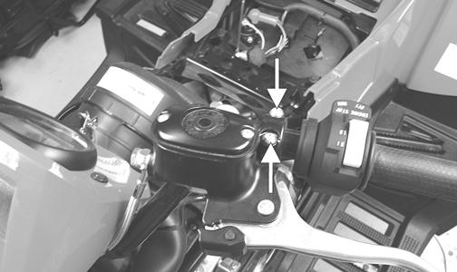
DE059A 3. Gently press the brakelight switch into the housing (left to right) until the mounting tabs snap into the four locating holes; then install the brake lever, pivot pin, and snap ring.
BC206 4. Bleed the brake system (see Periodic Maintenance/
Tune-Up).
Throttle Control
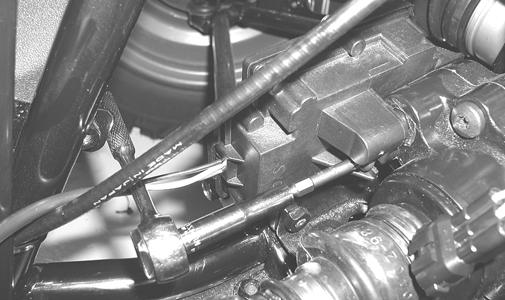
REMOVING 1. Remove the two machine screws securing the throttle control to the handlebar. 2. Slide the grommet out of the lower half of the throttle control; then remove the cable from the actuator arm.
AF676D 3. Remove the cap screw, lock washer, and washer securing the actuator arm to the throttle control lever.

AF677D 4. Remove the actuator arm and account for a bushing.
Note the position of the return spring for installing purposes.
AF678D
INSTALLING 1. Place the return spring into the throttle control; then place the bushing and actuator arm into position.
Secure with the cap screw, lock washer, and washer.

AF679D 2. Using a pair of needle-nose pliers, place the spring into position on the actuator arm.

AF680D 3. Place the two halves of the throttle control onto the handlebars and secure with the two machine screws. ADJUSTING To adjust throttle cable free-play, see Periodic Maintenance/Tune-Up.
Shift Lever
REMOVING 1. Remove the left-side splash panel. 2. Remove the E-clip securing the shift rod to the shift lever. 3. Remove the axle and nut securing the shift lever to the upper shift arm; then remove the shift lever.
Account for a spring and two O-rings. INSTALLING 1. Place the spring into position between the upper shift arm and shift lever; then making sure the O-rings are in place on the axle, secure the shift lever to the arm with the existing axle and nut. 2. Place the shift rod into position on the shift lever and secure with the existing E-clip. 3. Check shift lever adjustment (see Periodic Maintenance/Tune-Up section); then tighten jam nut(s) securely. 4. Install the left-side splash panel.
LCD Gauge
REPLACING 1. Remove the two reinstallable rivets securing the instrument pod; then remove the ignition switch retaining ring. 2. Remove the two nuts securing the mounting studs; then remove the speedometer from the instrument pod and disconnect the multi-pin connector. 3. Mount the speedometer in the instrument pod and secure with the two nuts; then connect the multi-pin connector. 4. Install the instrument pod and secure with the reinstallable rivets. 5. Secure the ignition switch with the retaining ring.
Steering Knuckles
REMOVING AND DISASSEMBLING 1. Secure the ATV on a support stand to elevate the wheel; then remove the wheel.
! WARNING
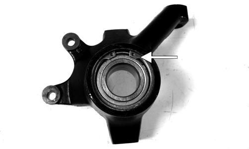
Make sure the ATV is solidly supported on the support stand to avoid injury. 2. Remove the wheel cap from the hub; then remove the cotter pin from the nut. 3. Remove the nut securing the hub. 4. Remove the brake caliper. 5. Remove the hub assembly. 6. Remove the cotter pin from the tie rod end and remove the tie rod end from the knuckle. 7. Remove the two cap screws securing the ball joints in the knuckle. 8. Tap the ball joint end out of the knuckle; then remove the knuckle. 9. Remove the snap ring from the knuckle; then remove the bearing.
PR287A

PR288
CAUTION
Use extreme care when removing the bearing. If the bearing is allowed to fall, it will be damaged and will have to be replaced.
CLEANING AND INSPECTING 1. Clean all knuckle components. 2. Inspect the bearing for pits, gouges, rusting, or premature wear. 3. Inspect the knuckle for cracks, breaks, or porosity. 4. Inspect threads for stripping or damage. ASSEMBLING AND INSTALLING 1. Install the bearing; then install the snap ring making sure it seats into the knuckle.
PR287A 2. Install the knuckle to the upper and lower ball joints and secure with the two cap screws. Tighten to 35 ftlb.
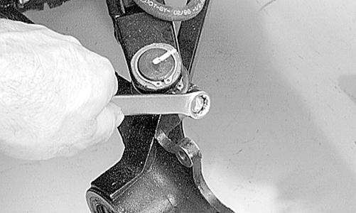
AF760D 3. Install the tie rod end and secure with the nut.
Tighten to 35 ft-lb; then install a new cotter pin and spread the pin. NOTE: During assembling, new cotter pins should be installed.

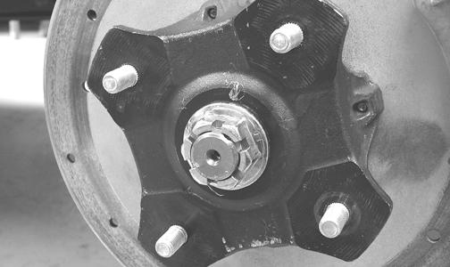
AF759D 4. Apply a small amount of grease to the hub splines.
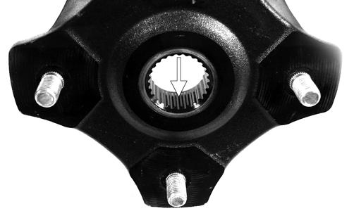
PR290A 5. Install the hub assembly onto the splines of the shaft. 6. Secure the hub assembly with the nut. Tighten only until snug.
PR257 7. Secure the brake caliper to the knuckle with new
“patch-lock” cap screws. Tighten to 20 ft-lb.

PR264A 8. Pump the hand brake lever; then engage the brake lever lock. 9. Tighten the hub nut (from step 6) to the shaft.
Tighten to 200 ft-lb. 10. Install a new cotter pin and spread the pin to secure the nut. 11. Install the wheel; then using a crisscross pattern, tighten to 45 ft-lb (steel wheels) or 80 ft-lb (aluminum wheels). 12. Remove the ATV from the support stand.
Measuring/Adjusting ToeIn
1. Thoroughly wash the ATV to remove excess weight (mud, etc.). 2. Refer to the specifications and ensure the tires are properly inflated to the recommended pressure. NOTE: Ensure the inflation pressure is correct in the tires or inaccurate measurements can occur.

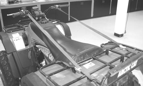
CD005 3. Place the ATV in a level position taking care not to push down or lift up on the front end; then turn the handlebar to the straight ahead position. NOTE: When measuring and adjusting, there should be a normal operating load on the ATV. 4. Measure the distance from the outside edge of each handlebar grip to equal reference points on each side.
DE047A 5. Adjust the handlebar direction until the two measurements are equal; then secure the handlebar to the rear rack using tie-down straps. NOTE: Care must be taken not to allow the handlebar to turn while securing it.
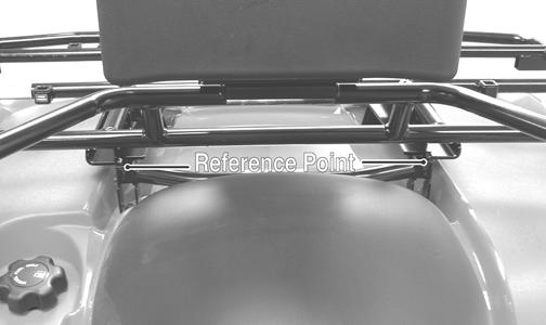
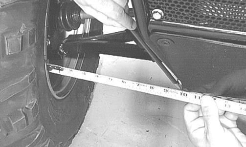
CD014 6. Measure the distance from the inside of each front rim to the lower frame tube.
AF785D
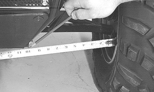
AF786D
NOTE: The distances from the inside rims to the frame tubes should be equal. If the measurements are equal, proceed to step 8; if the measurements are not equal, proceed to step 7. 7. To make the measurements equal, loosen the appropriate tie rod jam nuts and adjust accordingly; then proceed to step 8.

AF617D

AF778D
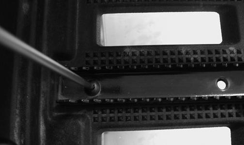
NOTE: The front wheels do not have to be removed to adjust the tie rod. Also, care should be taken not to disturb the handlebar position. 8. Using a permanent marker of some type, mark the center of each front tire (at a height parallel to the belly panel).
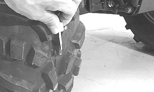
AF789D 9. Measure the distance between the marks (at a height parallel to the belly panel) at the front side; then record the measurement. 10. Push the ATV forward until the marks are parallel to the belly panel on the back side; then measure the distance between the marks. 11. The difference in the measurements must show 3.26.4 mm (1/8-1/4 in.) toe-in (the front measurement 3.2-6.4 mm (1/8-1/4 in.) less than the rear measurement). 12. If the difference in the measurements is not within specifications, adjust both tie rods equally until within specifications.
NOTE: Prior to locking the jam nuts, make sure the ball joints are at the center of their normal range of motion and at the correct angle.
733-559A
Front Rack
REMOVING 1. Remove the two shoulder screws and lock nuts securing the front fender panel. 2. Remove the cap screws and lock nuts securing the rack to the frame. 3. Remove the front rack from the ATV. CLEANING AND INSPECTING 1. Clean all rack components. 2. Inspect all welds for cracking or bending. 3. Inspect threaded areas of all mounting bosses for stripping. 4. Inspect for missing decals and/or reflectors. INSTALLING 1. Place the rack into position on the frame and front fender panel. Install the cap screws and lock nuts and finger-tighten only. 2. Install the two shoulder screws and lock nuts securing the rack to the fenders. Tighten all hardware securely.
Front Bumper Assembly
REMOVING 1. Remove the two flange bolts and lock nuts securing the upper bumper supports to the bumper. 2. Remove the through-bolt and lock nut securing the bumper to the frame; then remove the bumper. CLEANING AND INSPECTING 1. Clean all bumper components. 2. Inspect all welds for cracking or bending.
INSTALLING 1. Place the front bumper assembly into position and install the through-bolt. Start the lock nut and fingertighten only. 2. Install the two flange bolts and lock nuts on the upper supports. Tighten all hardware securely.
Footrests
REMOVING 1. Remove the machine screws and flange nuts securing the front and rear fenders to the footwells.

CD691A 2. Remove the cap screws securing the foot pegs to the footrests; then remove the foot pegs and footwells.
CD782 3. Remove the cap screws and flange nuts securing the footrests to the frame; then remove the footrests. CLEANING AND INSPECTING 1. Clean the footrest using a pressure washer. 2. Inspect the footrest weldments for cracks or unusual bends. 3. Inspect all tubing for cracks or unusual bends. INSTALLING 1. Secure the footrests to the frame with four cap screws and two flange nuts; then tighten securely. 2. Place the footwells onto the footrests; then put the foot pegs in position and secure with two cap screws.
Belly Panel
REMOVING/INSTALLING 1. Remove the machine screws and shoulder washers securing the belly panel to the underside of the frame; then remove the belly panel. 2. Place the belly panel into position on the underside of the frame; then install the machine screws and shoulder washers. Tighten securely.
Exhaust System
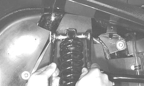
REMOVING MUFFLER 1. Remove the two exhaust springs at the muffler/ exhaust pipe juncture.

CF138A 2. Slide the muffler rearward to clear the mounting lugs and remove the muffler. INSPECTING MUFFLER 1. Inspect muffler externally for cracks, holes, and dents. 2. Inspect the muffler internally by shaking the muffler back and forth and listening for rattles or loose debris inside the muffler. NOTE: For details on cleaning the muffler/spark arrester, see Periodic Maintenance/Tune-Up. INSTALLING MUFFLER 1. Place the muffler into position engaging the mounting lugs into the grommets; then slide the muffler forward. 2. Install the two exhaust springs.
Taillight Assembly
REMOVING 1. Unplug the three-prong connector and free the taillight wiring harness from the frame. 2. Remove the torx-head cap screws securing the taillight assembly to the frame. Account for any washers. 3. Remove the taillight assembly. INSPECTING 1. Inspect wiring harness, three-prong connector, lens, base, cap screws, and socket for damage. 2. Inspect all wires for corroding, pinching, and cracking. 3. Inspect the bulb for wattage, voltage, and proper operation. INSTALLING 1. Place the assembly into position on the frame and secure with torx-head cap screws and any washers. 2. Tighten the cap screws securely. 3. Route the wiring harness over the rear frame; then connect the three-prong connector.
Seat
REMOVING/INSTALLING 1. To remove the seat, lift up on the latch release (located at the rear of the seat). Raise the rear of the seat and slide it rearward. 2. To lock the seat into position, slide the front of the seat into the seat retainers and push down firmly on the rear of seat. The seat should automatically lock into position.
Troubleshooting
Problem: Handling too heavy or stiff Condition Remedy 1. Front wheel alignment incorrect 1.Adjust alignment 2. Lubrication inadequate 2.Lubricate appropriate components 3. Tire inflation pressure low 3.Adjust pressure 4. Tie rod ends seizing 4.Replace tie rod ends 5. Linkage connections seizing 5.Repair - replace connections Problem: Steering oscillation Condition Remedy 1. Tires inflated unequally 1.Adjust pressure 2. Wheel(s) bent 2.Replace wheel(s) 3. Wheel lug nut(s) loose - missing 3.Replace lug nut(s) 4. Wheel hub bearing worn - damaged 4.Replace bearing 5. Tie rod ends worn - loose 5.Replace - tighten tie rod ends 6. Tires defective - incorrect 6.Replace tires 7. A-arm bushings damaged 7.Replace bushings 8. Bolts - nuts (frame) loose 8.Tighten bolts - nuts 9. Wheel stud(s) loose - missing 9.Replace wheel studs Problem: Steering pulling to one side Condition Remedy 1. Tires inflated unequally 1.Adjust pressure 2. Front wheel alignment incorrect 2.Adjust alignment 3. Wheel hub bearings worn - broken 3.Replace bearings 4. Frame distorted 4.Repair - replace frame 5. Shock absorber defective 5.Replace shock absorber Problem: Tire wear rapid or uneven Condition Remedy 1. Wheel hub bearings worn - loose 1.Replace bearings 2. Front wheel alignment incorrect 2.Adjust alignment 3. Tire inflation pressure incorrect 3.Adjust pressure Problem: Steering noise Condition Remedy 1. Cap screws - nuts loose 1.Tighten cap screws - nuts 2. Wheel hub bearings broken - damaged 2.Replace bearings 3. Lubrication inadequate 3.Lubricate appropriate components Problem: Rear wheel oscillation Condition Remedy 1. Rear wheel hub bearings worn - loose 1.Replace bearings 2. Tires defective - incorrect 2.Replace tires 3. Wheel rim distorted 3.Replace rim 4. Wheel lug nut(s) loose 4.Tighten - replace lug nut(s) 5. Axle shaft nut loose 5.Tighten nut 6. Rear suspension arm-related bushing worn 6.Replace bushing 7. Rear shock absorber damaged 7.Replace shock absorber 8. Rear suspension arm nut loose 8.Tighten nut 9. Wheel studs loose - missing 9.Replace wheel studs