47 minute read
Fuel/Lubrication/Cooling

SPECIAL TOOLS A number of special tools must be available to the technician when performing service procedures in this section. Refer to the current Special Tools Catalog for the appropriate tool description.
Description
Oil Pressure Test Kit Tachometer Fuel Pressure Test Kit
p/n
0644-495 0644-275 0644-571
NOTE: Special tools are available from the Arctic
Cat Service Department.
Electronic Fuel Injection
! WARNING
Whenever any maintenance or inspection is performed on the fuel system during which there may be fuel leakage, there should be no welding, smoking, open flames, etc., in the area.
TROUBLESHOOTING 1.Verify that the electric fuel pump is operating by listening for a “whirring” sound for several seconds after the ignition switch is turned to the ON position.
If no sound can be heard, see Electric Fuel Pump/
Fuel Level Sensor in this section.
2.Check for a flashing Diagnostic Trouble Code (DTC) and a Malfunction Indicator Light (MIL) in the form of a wrench icon on the LCD. If a code is flashing, see Diagnostic Trouble Codes (DTC) in Electrical
System. 3.Make sure there is sufficient, clean gas in the gas tank.
4.Verify that the battery is sufficiently charged to crank the engine over at normal speed. 5.Check the air filter housing and air filter for contamination. Clean or replace as necessary (see Periodic
Maintenance).
Throttle Body
REMOVING 1.Remove the heat shields and seat.
2.Disconnect the negative battery cable; then remove the gas tank (see Gas Tank in this section). 3.Loosen the clamp securing the intake boot to the throttle body; then loosen the clamp securing the intake boot to the intake housing and slide the intake housing rearward.
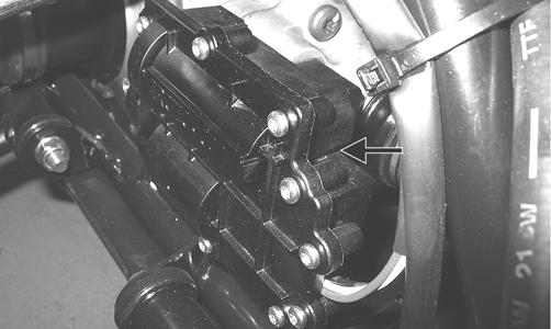
Gasoline may be under pressure. Place an absorbent towel under the connector to absorb any gasoline spray when disconnecting.
FI691A
4.Disconnect the MAP/IAT sensor connector, ISC connector, and TPS connector; then loosen the clamp securing the throttle body to the intake manifold boot and slide the throttle body out.
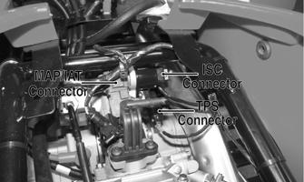
FI528A
5.Remove the throttle arm cover and loosen the throttle cable jam nut; then disconnect the throttle cable and remove the throttle body. INSTALLING 1.Connect the throttle cable to the throttle arm; then install the throttle cable housing in the throttle body and tighten the jam nut. Install the throttle arm cover and secure with two machine screws.
2.Place the throttle body into the intake manifold boot and tighten the boot clamp securely. 3.Place the intake housing into the boots and tighten the boot clamps securely. 4.Install the gas tank; then the heat shields and seat.
Throttle Cable Free-Play
To adjust throttle cable free-play, see Periodic Maintenance.
Gas Tank
! WARNING
Whenever any maintenance or inspection is made on the fuel system during which there may be fuel leakage, there should be no welding, smoking, open flames, etc., in the area.
REMOVING 1.Remove the battery case access cover from the battery case; then disconnect the negative battery cable and remove the seat.
2.Remove the reinstallable rivets securing the side panels (two on each side) and remove the side panels.
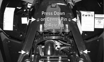
KC450A
NOTE: The reinstallable rivets may be easily
released by depressing the pin in the center of the head.
3.Remove two cap screws and four reinstallable rivets from the gas tank cover; then remove the gas tank cap and remove the cover panel. Reinstall the gas tank cap.
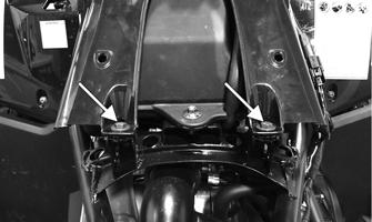
KC454A
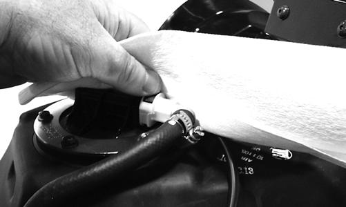
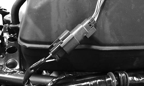
4.Using a shop towel to catch any leaking gasoline, disconnect the gasline hose from the fuel pump outlet; then disconnect the fuel pump/fuel gauge connector from the harness.
KC455
KC456
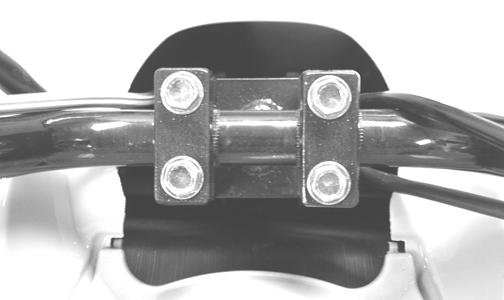
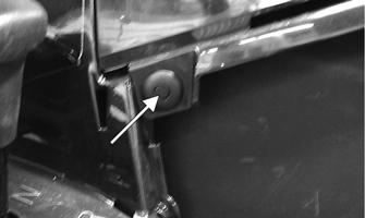
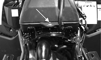
5.Remove the mounting bolt at the rear of the gas tank; then remove the gas tank.
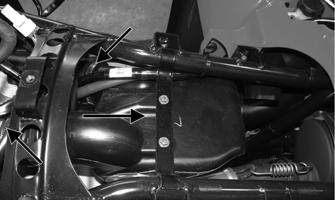
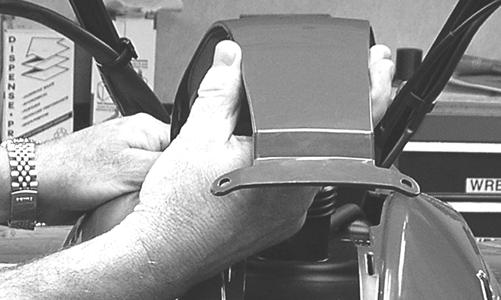
6.Remove the heat shield by reaching under the front of the shield and compressing the retainer posts to release.
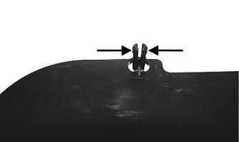
KC459A
CLEANING AND INSPECTING NOTE: Whenever a part is worn excessively,
cracked, or damaged in any way, replacement is necessary.
1.Clean all gas tank components with parts-cleaning solvent.
2.Inspect all hoses for cracks or leaks. 3.Inspect tank cap and tank for leaks, holes, and damaged threads. INSTALLING 1.Install the heat shield making sure the mounting studs lock in the bracket; then install the gas tank and secure with the mounting bolt. Tighten securely.
KC458A
2.Connect the gasline connector to the fuel pump outlet making sure it locks securely in place; then connect the fuel pump/fuel gauge connector to the harness.
3.Remove the gas tank cap and place the gas tank cover over the gas tank. Install the gas tank cap; then secure the cover with two reinstallable rivets and two cap screws. 4.Install the side panels and secure with four reinstallable rivets making sure the tabs on the panels engage the slots on the gas tank cover. 5.Connect the negative battery cable and install the battery case access cover; then install the seat.
Oil Filter/Oil Pump
NOTE: Whenever internal engine components wear
excessively or break and whenever oil is contaminated, the oil pump should be replaced. The oil pump is not a serviceable component.
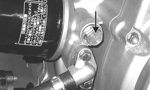
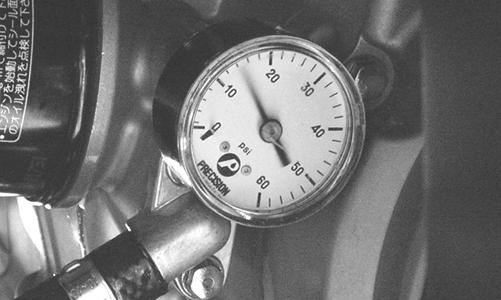
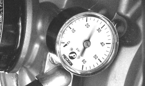
Testing Oil Pump Pressure
1.Connect the Tachometer to the engine. 2.Connect the Oil Pressure Test Kit to the oil filter drain plug.
KC195A
KC267
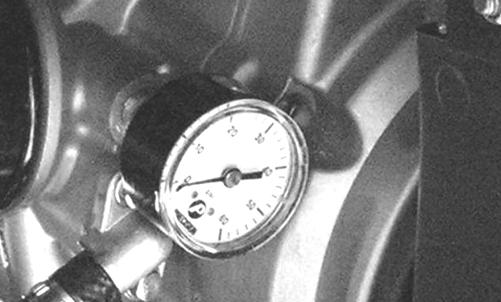
NOTE: Some oil seepage may occur when installing
the oil pressure gauge. Wipe up oil residue with a cloth.
3.Warm up the engine to normal operating temperature (cooling fan cycling); then increase engine RPM to 3000 RPM. The oil pressure must read 0.6-0.7 kg/ cm2 (8.5-17 psi).
KC268
KC269
NOTE: If the oil pressure is lower than specified,
check for low oil level or defective oil pump.
NOTE: If the oil pressure is higher than specified,
check for clogged oil passage, clogged oil filter, or improper installation of the oil filter.
Liquid Cooling System
When filling the cooling system, use premixed Arctic Cat Antifreeze. While the cooling system is being filled, air pockets may develop; therefore, run the engine for five minutes after the initial fill, shut the engine off, and then fill the cooling system to the bottom of the stand pipe in the radiator neck.
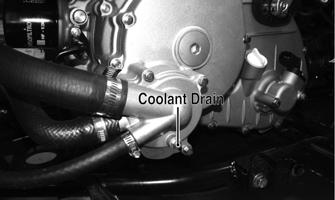
RADIATOR Removing 1.Drain the coolant at the engine. 2.Remove the radiator/electrical access panel and front fender panel (see Steering/Frame). 3.Remove the upper and lower coolant hoses; then remove the fill hose and air bleed hose. 5.Disconnect the fan wiring from the main wiring harness; then remove the radiator/fan assembly and account for the grommets and collars. 6.Remove the fan/fan shroud assembly from the radiator.
CAUTION
After operating the ATV for the initial 5-10 minutes, stop the engine, allow the engine to cool down, and check the coolant level. Add coolant as necessary.
Cleaning and Inspecting NOTE: Whenever a part is worn excessively,
cracked, or damaged in any way, replacement is necessary.
1.Flush the radiator with water to remove any contaminants.
2.Inspect the radiator for leaks and damage. 3.Inspect all hoses for cracks and deterioration. 4.Inspect all fasteners and grommets for damage or wear.
Installing 1.Position the fan/fan shroud assembly on the radiator; then secure with existing hardware. 2.Place the radiator with grommets and collars into position on the frame; then install the cap screws.
Tighten securely. 3.Install the upper and lower coolant hoses, fill hose, and air bleed hose; then secure with hose clamps.
AF734D
4.Install the fender panel (see Steering/Frame). 5.Fill the cooling system with the recommended amount of antifreeze. Check for leakage. 6.Connect the fan wiring to the main wiring harness. THERMOSTAT Removing 1.Drain approximately one quart of coolant from the cooling system.
2.Remove the two cap screws securing the thermostat housing to the mounting bracket. Remove the thermostat housing cover and account for an O-ring and a thermostat.
Inspecting NOTE: Whenever a part is worn excessively, cracked,
or damaged in any way, replacement is necessary.
1.Inspect the thermostat for corrosion or spring damage. 2.Using the following procedure, inspect the thermostat for proper operation.
A.Suspend the thermostat in a container filled with water.
B.Heat the water and monitor the temperature with a thermometer.
C.The thermostat should start to open at 71-86° C (160-187° F).
D.If the thermostat does not open, it must be replaced. 3.Inspect all coolant hoses, connections, and clamps for deterioration, cracks, and wear. NOTE: All coolant hoses and clamps should be
replaced every four years or 4000 miles.
Installing 1.Place the thermostat and O-ring into the thermostat housing; then secure the thermostat housing to the mounting bracket with the two cap screws. 2.Fill the cooling system to the recommended level with antifreeze. Check for leakage. WATER PUMP NOTE: The water pump is a non-serviceable compo-
nent. It must be replaced as an assembly.
Removing 1.Remove the radiator cap; then remove the water pump drain and drain the coolant.
FI530A
2.Drain the oil from the engine/transmission. 3.Remove the four torx-head cap screws securing the front and rear fenders to the footrest; then remove the four cap screws securing the footrest to the frame.
Remove the footrest.
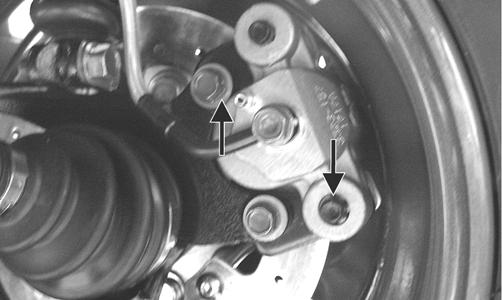
4.Loosen the hose clamps and slide the clamps away from the hose ends approximately 2 in.; then remove the hoses from the water pump. 5.Remove the four cap screws securing the water pump to the engine; then remove the water pump.
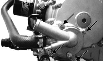
FI538A
Installing 1.Secure the water pump to the engine with the four cap screws tightened to 8 ft-lb.
FI538A
2.Connect the coolant hoses to the water pump and secure with the clamps. Tighten securely.
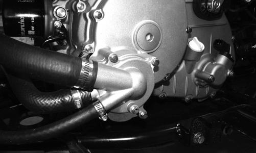
FI530
3.Place the footrest into position on the frame and loosely secure with four cap screws; then secure the front and rear fenders to the footrest with the four torx-head cap screws. Tighten the four torx-head cap screws securely; then tighten the remaining cap screws to 20 ft-lb.
4.Fill the engine/transmission with the proper amount of recommended oil.
5.Fill the cooling system with the proper amount of recommended coolant.
Electric Fuel Pump/Fuel Level Sensor
The electric fuel pump and fuel level sensor are not serviceable components. If either component fails, it must be replaced. TESTING
1.Turn the ignition switch ON and listen for a momentary “whirring” sound of the pump building pressure.
If the sound is heard (10 seconds), no electrical checks are necessary. Turn the ignition switch OFF. 2.Disconnect the gasline hose from the throttle body; then install a suitable pressure gauge.
! WARNING
Whenever any maintenance or inspection is made on the fuel system during which there may be fuel leakage, there should be no welding, smoking, open flames, etc., in the area.
AT THIS POINT
Prior to removing the electric fuel pump, the following check should be performed to determine that removal is necessary.
! WARNING
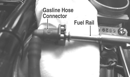
Gasoline may be under pressure. Place an absorbent towel under the connector to absorb any gasoline spray when disconnecting.
FI092A
3.Turn the ignition switch to the ON position. The fuel pressure should build until the pump shuts off. Pressure should read 3.0 kg-cm2 (43 psi). 4.If the pump is not running, disconnect the fuel pump/ tank sensor connector located behind the right side panel. 5.Connect a multimeter to the power supply leads with the red tester lead to the red wire and the black tester lead to the black wire; then turn the ignition switch to the ON position. The meter should read battery voltage. If battery voltage is indicated and the fuel pump does not run, replace the pump assembly. If no battery voltage is indicated, check the ECU and the vehicle tilt sensor. REMOVING 1.Disconnect the negative battery cable from the battery. 2.Remove the side panels and gas tank cover (see Gas
Tank in this section).
KC220
3.Mark the fuel pump and gas tank for proper orientation during assembly; then disconnect the fuel pump/ fuel level sender connector.
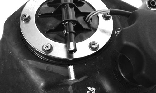
KC423
4.Disconnect the gasline connector from the fuel pump outlet.
5.Remove the screws securing the fuel pump to the gas tank; then make a reference mark on the fuel pump and tank.
6.Lift out the fuel pump assembly and carefully guide the pump and float lever through the opening in the gas tank. ! WARNING
Gasoline may be under pressure. Place an absorbent towel under the connector to absorb any gasoline spray when disconnecting.
! WARNING
Do not turn the ignition switch to the ON position with the hoses removed. Gasoline will be pumped by the electric fuel pump causing a safety hazard.
CAUTION
Take care not to damage the float or float arm or replacement of the entire assembly will be necessary.
7.Using duct tape or other suitable means, cover the fuel pump opening. INSPECTING
1.Inspect the fuel screen and blow clean with low pressure compressed air. 2.Move the float lever and check for free movement.
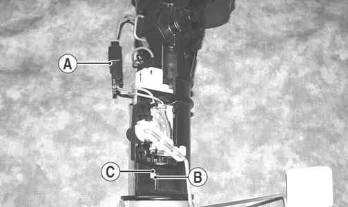
The float assembly should return to the lower position without force. If not, replace the fuel pump assembly. 3.Test the fuel level sensor by connecting a multimeter (A) to the fuel level sensor leads (B); then select
OHMS. The multimeter should show 5 ohms at full fuel position (C) and 95 ohms at empty fuel position (D). AT THIS POINT
If the pump has failed earlier test and must be replaced, proceed to INSTALLING.
ATV2116
NOTE: If readings are erratic, clean the resistor
wiper and resistor with clean alcohol and retest. If still not correct, replace the fuel level sensor.
4.To replace the fuel level sensor, use the following procedure.
A.Disconnect the two-wire connector (A); then press the fuel level sensor toward the top of the fuel pump to release it from the mounting slot (B).
FI460A
B.Engage the tabs (C) of the fuel level sensor into the mounting slot (B) and press toward the bottom of the fuel pump to latch in place; then connect the two-wire connector (A). INSTALLING 1.Mark the new fuel pump with a reference mark in the same location as the removed pump; then place the new gasket on the pump. 2.Remove the material covering the fuel pump opening; then carefully guide the fuel pump into position taking care not to damage the float or float lever.
KX190
3.Rotate the fuel pump until the match marks align; then install the mounting screws and tighten securely using a crisscross pattern. NOTE: It is important to install the fuel pump with
the correct orientation to ensure adequate float lever clearance.
4.Connect the wires and fuel hose; then connect the negative battery cable and turn the ignition switch to the ON position. Note that the fuel pump runs momentarily and the fuel gauge indicates the proper fuel level.
5.With the transmission in neutral and brake lever lock engaged, start the engine and check for normal operation. Check for any fuel leaks. 6.Install the side panels and gas tank cover (see Gas
Tank in this section).
Troubleshooting
Problem: Starting impaired Condition Remedy
1. Gas contaminated 1.Drain gas tank and fill with clean gas
Problem: Idling or low speed impaired Condition Remedy
1. TPS out of adjustment 1.Adjust TPS
Problem: Medium or high speed impaired Condition Remedy
1. High RPM “cut out” against RPM limiter 1.Decrease RPM speed
Electrical System Battery
This section has been organized into sub-sections which show procedures for the complete servicing of the Arctic Cat ATV electrical system. SPECIAL TOOLS A number of special tools must be available to the technician when performing service procedures in this section. Refer to the current Special Tools Catalog for the appropriate tool description.
Description
Fluke Model 73 Multimeter Fluke Model 77 Multimeter MaxiClips
p/n
0644-191 0644-559 0744-041
NOTE: Special tools are available from the Arctic
Cat Service Department.
Specifications
Ignition Timing 10° BTDC @ 1500 RPM Spark Plug Type NGK CR7E Spark Plug Gap 0.7-0.8 mm (0.028-0.032 in.) Spark Plug Cap 5000 ohms Ignition Coil (primary) Less than 5.0 ohms Resistance (terminal (+) to terminal (-)) (secondary) 12k-19k ohms (high tension - plug cap to terminal (+)) Ignition Coil Primary Voltage Battery Voltage (orange (+) to blue/white(-))
Stator Coil Resistance (crankshaft position sensor) (AC generator) 150-250 ohms (blue to green) Less than 1 ohm (black to black)
Crankshaft Position Sensor AC Voltage 2.5 volts or more (blue to green)
AC Generator (no load) Output 60 AC volts @ 5000 RPM (black to black)
Electrical Connections
The electrical connections should be checked periodically for proper function. In case of an electrical failure, check fuses, connections (for tightness, corrosion, damage), and/or bulbs. After being in service, batteries require regular cleaning and recharging in order to deliver peak performance and maximum service life. The following procedure is recommended for cleaning and maintaining sealed batteries. Always read and follow instructions provided with battery chargers and battery products.
1.Remove the battery case access cover; then disconnect the battery cables (negative cable first). 2.Remove the battery from the battery case; then thoroughly wash the battery and battery case with soap and water. ! WARNING
Any time service is performed on a battery, the following must be observed: keep sparks, open flame, cigarettes, or any other flame away. Always wear safety glasses. Protect skin and clothing when handling a battery. When servicing battery in enclosed space, keep the area well-ventilated. Make sure battery venting is not obstructed.
NOTE: If battery posts, cable ends, or the battery
case has a build-up of white/green powder residue, apply water and baking soda to neutralize acid; then flush off with warm soapy water.
3.Using a wire brush, clean the battery posts and cable ends removing all corrosive buildup. Replace damaged cables or cable ends.
! WARNING
Battery acid is harmful if it contacts eyes, skin, or clothing. Care must be taken whenever handling a battery.
4.Using a multimeter, test the battery voltage. The meter must read 12.5 or more DC Volts for a fully charged battery. NOTE: At this point, if the meter reads as specified,
the battery may be returned to service (see step 8).
5.If the meter reads less than specified voltage, charge the battery using the following guidelines.
A.When using an automatic battery charger, always follow the charger manufacturer’s instructions.
B.When using a constant-current battery charger, use the following Battery Charging Chart.
CAUTION
Never exceed the standard charging rate.
! WARNING
An overheated battery could explode causing severe injury or death. Always monitor charging times and charge rates carefully. Stop charging if the battery becomes very warm to the touch. Allow it to cool before resuming charging.
Battery Charging Chart (Constant-Current Charger)
Battery Voltage Charge Charge Time Required (DC) State (at 1.5-2.0 Amps)
12.5 or more 100% None 12.2-12.4 75%-99% 3-6 hours 12.0-12.2 50%-74% 5-11 hours 11.0-11.9 25%-49% 13 hours (minimum) 11.5 or less 0-24% 20 hours (minimum) NOTE: If the battery voltage is 11.5 DC Volts or less,
some chargers may “cut off” and fail to charge. If this occurs, connect a fully charged booster battery in parallel (positive to positive and negative to negative) for a short period of time with the charger connected. After 10-15 minutes, disconnect the booster battery leaving the charger connected and the charger should continue to charge. If the charger “cuts off,” replace the battery.
6.After charging the battery for the specified time, remove the battery charger and allow the battery to sit for 1-2 hours.
7.Connect the multimeter and test the battery voltage.
The meter should read 12.5 or more DC Volts. If the voltage is as specified, the battery is ready for service.
NOTE: If voltage in step 7 is below specifications,
charge the battery an additional 1-5 hours; then retest.
8.Place the battery in the battery case; then coat the battery posts and cable ends with a light coat of multi-purpose grease.
9.Connect the battery cables (positive cable first); then install the battery case access cover.
CAUTION
Before installing the battery, make sure the ignition switch is in the OFF position.
CAUTION
Connecting cables in reverse (positive to negative and negative to positive) can cause serious damage to the electrical system.
RPM Limiter
NOTE: The ATV is equipped with an ECU that
retards ignition timing when maximum RPM is approached. When the RPM limiter is activated, it could be misinterpreted as a high-speed misfire.
Testing Electrical Components
All of the electrical tests should be made using the Fluke Model 73 Multimeter or Fluke Model 77 Multimeter and when testing peak voltage, the Peak Voltage Reading Adapter must be used. If any other type of meter is used, readings may vary due to internal circuitry. When troubleshooting a specific component, always verify first that the fuse(s) are good, that the bulb(s) are good, that the connections are clean and tight, that the battery is fully charged, and that all appropriate switches are activated. NOTE: For absolute accuracy, all tests should be
made at room temperature of 68° F.
Accessory Receptacle/ Connector
NOTE: This test procedure is for either the recepta-
cle or the connector.
VOLTAGE 1.Turn the ignition switch to the ON position; then set the meter selector to the DC Voltage position. 2.Connect the red tester lead to the red wire; then connect the black tester lead to ground. 3.The meter must show battery voltage. NOTE: If the meter shows no battery voltage, trou-
bleshoot the battery, fuse, receptacle, connector, or the main wiring harness.
Brakelight Switch (Pressure)
The brakelight switch is located on the top of the brake master cylinder and is pressure activated by the hand brake or the brake pedal. This switch also activates the start-in-gear (SIG) relay in the power distribution module (PDM). NOTE: The ignition switch must be in the ON posi-
tion.
VOLTAGE (Wiring Harness Side) 1.Set the meter selector to the DC Voltage position. 2.Connect the red tester to the brown/black wire; then connect the black tester lead to ground. 3.The meter must show battery voltage.
NOTE: If the meter shows no battery voltage, trou-
bleshoot the battery, fuse, switch, or the main wiring harness.
NOTE: If the meter shows battery voltage, the main
wiring harness is good; proceed to test the switch/ component or connector.
RESISTANCE (Switch) 1.Remove the spade connectors from the brake switch. 2.Set the meter selector to the OHMS position. 3.Connect the red tester lead to one switch terminal; then connect the black tester lead to the other switch terminal.
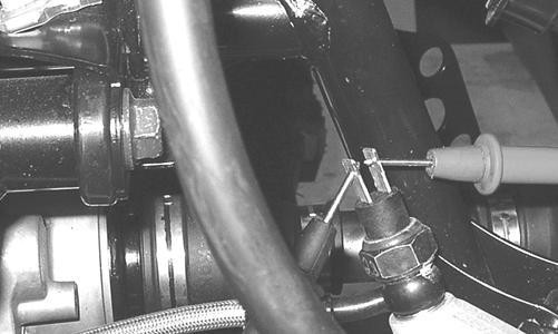
KC274
4.When the brake pedal is depressed, the meter must show less than 1 ohm.
NOTE: If the meter shows more than 1 ohm of resis-
tance, replace the switch.
Engine Coolant Temperature (ECT) Sensor
1.Connect the meter leads (selector in OHMS position) to the sensor terminals.
2.Suspend the sensor and a thermometer in a container of cooking oil; then heat the oil. NOTE: Neither the sensor nor the thermometer
should be allowed to touch the bottom of the container or inaccurate readings will occur. Use wire holders to suspend the sensor and thermometer.
! WARNING
Wear insulated gloves and safety glasses. Heated oil can cause severe burns.
3.On the ECT sensor when the temperature reaches 20° C (68° F), the meter should read approximately 2.45k ohms. 4.On the ECT sensor when the temperature reaches 50° C (122° F), the meter should read approximately 800 ohms.
5.On the ECT sensor when the temperature reaches 80° C (176° F), the meter should read approximately 318 ohms.
6.On the ECT sensor when the temperature reaches 110° C (230° F), the meter should read approximately 142 ohms. 7.If the readings are not as indicated, the sensor must be replaced. 8.Install the sensor and tighten securely. 9.Connect the leads.
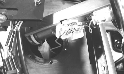
Fan Motor
The connector is the black two-prong one located behind the fan assembly along the right-side frame tube.
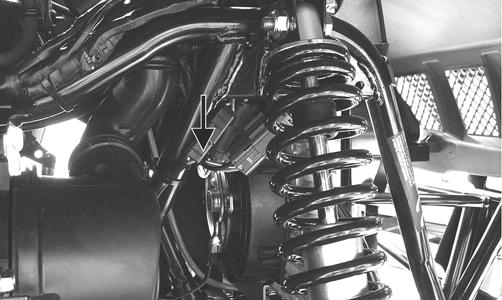
KC270A
NOTE: The ignition switch must be in the ON posi-
tion.
VOLTAGE (Main Harness Connector to Fan Motor) 1.Set the meter selector to the DC Voltage position. 2.Connect the red tester lead to the orange wire; then connect the black tester lead to ground. 3.The meter must show battery voltage. NOTE: If the meter shows no battery voltage, trou-
bleshoot the battery, fuse, motor, or the main wiring harness.
NOTE: If the meter shows battery voltage, the main
wiring harness is good. The connector should be checked for resistance.
RESISTANCE (Fan Motor Connector) 1.Set the meter selector to the OHMS position. 2.Connect the red tester lead to the red wire; then connect the black tester lead to the black wire.
NOTE: If the meter shows more than 1 ohm of resis-
tance, troubleshoot or replace the switch/component, the connector, or the switch wiring harness.
NOTE: To determine if the fan motor is good, con-
nect the blue wire from the fan connector to the positive side of a 12 volt DC power supply; then connect the black wire from the fan connector to the negative side. The fan should operate.
! WARNING
Care should be taken to keep clear of the fan blades.
Power Distribution Module (PDM)
The fuses are located in the power distribution module in front of the steering post under the radiator/electrical access panel.

KC466A
If there is any type of electrical system failure, always check the fuses first.
NOTE: To remove a fuse, compress the locking tabs
on either end of the PDM cover and lift off; then remove the applicable fuse.
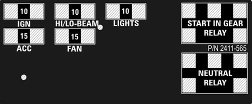
2411-565
CAUTION
Always replace a blown fuse with a fuse of the same type and rating.
RELAYS The relays are identical plug-in type located on the PDM. Relay function can be checked by switching relay positions. The relays are interchangeable. NOTE: The PDM and wiring harness are not a ser-
viceable components and must be replaced as an assembly.
Ignition Coil
The ignition coil is on the frame above the radiator. To access the coil, the radiator/electrical access panel must be removed.
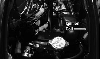
KC466B
RESISTANCE NOTE: For these tests, the meter selector must be
set to the OHMS position and the primary plug disconnected.
Primary Winding 1.Connect the red tester lead to either terminal; then connect the black tester lead to the other terminal.
2.The meter reading must be within specification. Secondary Winding 1.Remove the plug cap from the high tension lead; then connect the red tester lead to the high tension lead.
2.Connect the black tester lead to ground. 3.The meter reading must be within specification. NOTE: If the meter does not show as specified,
replace ignition coil.
Spark Plug Cap 1.Connect the red tester lead to one end of the cap; then connect the black tester lead to the other end of the cap.
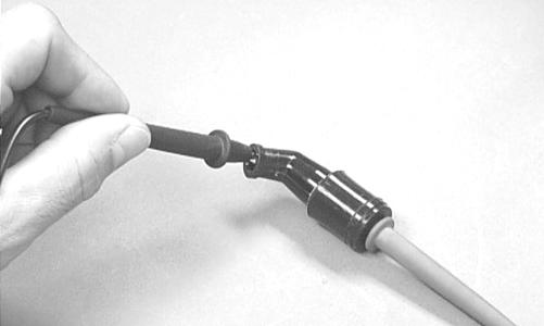
AR603D
2.The meter reading must be within specification. NOTE: If the meter does not read as specified,
replace the spark plug cap.
CD071
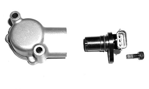
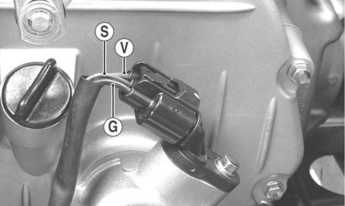
Speed Sensor Ignition Switch
1.Set the meter selector to the DC Voltage position. 2.With appropriate needle adapters on the meter leads, connect the red tester lead to the voltage lead (V); then connect the black tester lead to the ground lead (G).
KC248A
3.Turn the ignition switch to the ON position. 4.The meter must show greater than 5.0 volts. 5.Leave the black tester lead connected; then connect the red tester lead to the signal lead pin (S). 6.Slowly move the ATV forward or backward; the meter must show 0 and >5 volts alternately. NOTE: If the sensor tests are within specifications,
the speedometer/LCD gauge must be replaced (see Steering/Frame).
To replace a speed sensor, use the following procedure. 1.Disconnect the three-wire connector from the speed sensor; then remove the cap screw securing the sensor to the sensor housing. 2.Remove the sensor from the sensor housing accounting for an O-ring. 3.Install the new speed sensor into the housing with new O-ring lightly coated with multi-purpose grease; then secure the sensor with the cap screw (threads coated with blue Loctite #242). Tighten securely.
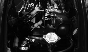
The ignition switch harness connects to the switch with a three-pin connector. To access the connector, remove the radiator/electrical access panel.
KC466C
VOLTAGE NOTE: Perform this test on the main harness con-
nector.
1.Set the meter selector to the DC Voltage position. 2.Connect the red meter lead to the red/white wire; then connect the black meter lead to ground. 3.Meter must show battery voltage. NOTE: If the meter shows no battery voltage, trou-
bleshoot the battery or the main wiring harness.
RESISTANCE NOTE: Perform this test on the switch harness
using the following procedure.
KC276A
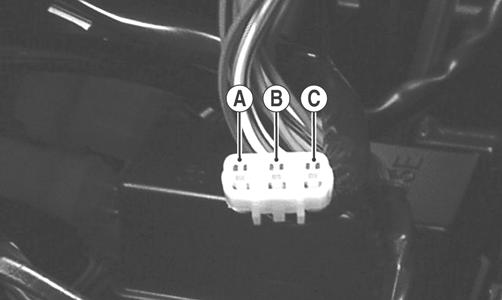
1.Turn the ignition switch to the ON position. 2.Set the meter selector to the OHMS position. 3.Connect either tester lead to pin B; then connect the other tester lead to pin A. 4.The meter must show less than 1 ohm.
5.Turn the ignition switch to the LIGHTS position.
The meter must show less than 1 ohm.
6.Leaving the tester lead on pin B, connect the other tester lead to pin C. 7.The meter must show less than 1 ohm.
NOTE: If the meter shows more than 1 ohm of resis-
tance, replace the switch.
RESISTANCE (Emergency Stop) 1.Set the meter selector to the OHMS position. 2.Connect the one lead to the brown/lavender wire; then connect the other tester lead to the black/white wire.
3.With the switch in the OFF position, the meter must show an open circuit. 4.With the switch in the RUN position, the meter must show less than 1 ohm.
NOTE: If the meter shows more than 1 ohm of resis-
tance, replace the switch.
RESISTANCE (Reverse Override) NOTE: The handlebar control switch connectors are
a six pin and a three pin. Both must be disconnected for this test.
1.Set the meter selector to the OHMS position. 2.Connect one tester lead to one lavender/red wire (three-pin connector); then connect the other tester wire to the green/red wire on the six-pin connector.
The meter must show less than 1 ohm.
3.Depress and hold the reverse override button. The meter must show an open circuit. NOTE: If the meter does not show as specified,
replace the switch.
The connectors are located on the right side of the ATV next to the PDM. To access the connector, the radiator/ electrical access panel must be removed. NOTE: These tests should be made on the switch
side of the connector.
RESISTANCE (HI Beam) 1.Set the meter selector to the OHMS position. 2.Connect one tester lead to the brown/black wire; then connect the other tester lead to the lavender wire.
3.With the dimmer switch in the HI position, the meter must show less than 1 ohm.
NOTE: If the meter shows more than 1 ohm of resis-
tance, replace the switch.
RESISTANCE (LO Beam) 1.Connect one tester lead to the brown/black wire; then connect the other tester lead to the white wire.
2.With the dimmer switch in the LO position, the meter must show less than 1 ohm. The connector is the snap-lock one in front of the steering post. To access the connector, the radiator/electrical access panel cover must be removed. NOTE: Resistance tests should be made with the
connector disconnected and on the selector-side of the connector.
RESISTANCE 1.Set the meter selector to the OHMS position. 2.Connect the one tester lead to the white/blue wire; then connect the other tester lead to the black wire.
3.With the selector switch in the 2WD position, the meter must show an open circuit. 4.With the selector switch in the 4WD position, the meter must show less than 1 ohm.
NOTE: If the meter does not show as specified,
replace the front drive selector switch.
VOLTAGE NOTE: The battery must be connected when per-
forming voltage tests.
1.Set the meter selector to the DC Voltage position. 2.Connect the black tester lead to the negative battery terminal.
3.Connect the red tester lead to the white/blue wire on the harness side of the connector.
4.Turn the ignition switch to the RUN position. 5.The meter must show battery voltage. NOTE: If the meter shows other than specified,
check the harness, connector, 30 amp fuse, and battery connections.
Front Drive Selector Actuator
NOTE: With the engine stopped and the ignition
switch in the ON position, a momentary “whirring” sound must be noticeable each time the selector switch is moved to 2WD and 4WD. Test the switch, 30 amp fuse, and wiring connections prior to testing the actuator.
VOLTAGE 1.Select the 2WD position on the front drive selector switch; then disconnect the connector on the actuator wiring harness. 2.With the ignition switch in the OFF position, connect the black tester lead to the black wire in the supply harness; then connect the red tester lead to either orange wire in the supply harness. 3.Turn the ignition switch to the ON position. The meter must show 12 DC volts.
4.Connect the red tester lead to the second orange wire in the supply harness. The meter must show 12 DC volts.
5.Connect the red tester lead to the white/green wire in the supply harness. The meter must show 12 DC volts.
6.Select the 4WD position on the front drive selector switch; then connect the red tester lead to the white/ blue wire in the supply harness. The meter must show 0 DC volts.
NOTE: The 4WD icon on the LCD should illuminate.
NOTE: If the voltage readings are as specified and
the actuator does not function correctly, replace the actuator (see Drive System).
Gear Position Switch
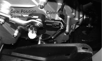
FI525B
To troubleshoot the switch, use the following procedure. 1.Disconnect the gear position switch connector; then using a multimeter, test the switch in each position as follows. Resistance must be less than 1 ohm for all tests.
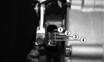
KC410A
A.Neutral (N)Pins 3 to 4
B.Reverse (R)Pins 3 to 4 and 3 to 2
C.High (H)Pins 3 to 4 and 3 to 1
D.Low (L)Pins 3 to 1 2.Connect the harness to the gear position switch.
Stator Coil
VOLTAGE (AC Generator - Regulated Output) 1.Set the meter selector to the DC Voltage position. 2.Connect the red tester lead to the positive battery post; then connect the black tester lead to the negative battery post. 3.With the engine running at a constant 3000 RPM (with the headlights on), the meter must show 1415.5 DC volts.
CAUTION
Do not run the engine at high RPM for more than 10 seconds.
VOLTAGE (AC Generator Coil - No Load) The connector is the black three-pin one on the right side of the engine just above the starter motor. NOTE: Test the engine-side of the connector.
1.Set the meter selector to the AC Voltage position. 2.Test between the three black wires for a total of three tests.
3.With the engine running at the specified RPM, all wire tests must show 60 AC volts.
CAUTION
Do not run the engine at high RPM for more than 10 seconds.
NOTE: If both AC Generator coil tests failed, check
all connections, etc., and test again. If no voltage is present, replace the stator assembly.
RESISTANCE (AC Generator Coil) 1.Set the meter selector to OHMS position. 2.Test between the three black wires for a total of three tests.
3.The meter reading must be within specification. RESISTANCE (Crankshaft Position Sensor) 1.Disconnect the gray four-pin connector on the right side of the engine just above the starter motor. 2.Set the meter selector to the OHMS position. 3.Connect the red tester lead to the green wire; then connect the black tester lead to the blue wire. The meter reading must be within specification. NOTE: The battery must be at full charge for this test.
VOLTAGE (Crankshaft Position Sensor) 1.Set the meter selector to the DC Voltage position. 2.Connect the red tester lead to the green wire; then connect the black tester lead to the blue wire.
3.Crank the engine over using the electric starter. 4.The meter reading must be within specification.
Starter Relay
1.Remove the battery case access cover; then using the multimeter set to the DC Voltage position, check the relay as follows.
2.Connect the red tester lead to the positive battery terminal; then connect the black tester lead to the starter cable connection on the starter relay. The meter must show battery voltage. NOTE: Make sure that the ignition switch is in the ON
position, transmission in neutral, brake lock released, and the emergency stop switch in the RUN position.
3.Depress the starter button while observing the multimeter. The multimeter should drop to 0 volts, a
“click” should be heard from the relay, and the starter motor should run.
NOTE: If a “click” is heard and any voltage is indi-
cated by the multimeter, replace the starter relay. If no “click” is heard and the multimeter continues to indicate battery voltage, test the neutral start relay.
Starter Motor
NOTE: The starter is a non-serviceable component.
If the following test does not result as specified, the starter must be replaced.
TESTING VOLTAGE Perform this test on the starter motor positive terminal. To access the terminal, slide the boot away. NOTE: The ignition switch must be in the ON posi-
tion, the emergency stop switch in the RUN position, and the shift lever in the NEUTRAL position.
1.Set the meter selector to the DC Voltage position. 2.Connect the red tester lead to the starter terminal; then connect the black tester lead to ground. 3.With the starter button depressed, the meter must show approximately 10.0 DC volts and the starter motor should operate.
AR607D
NOTE: If the meter showed correct voltage but the
starter did not operate or operated slowly, the starter motor is defective.
NOTE: If the meter showed no voltage, inspect
ground connections, starter motor lead, battery voltage (at the battery), starter relay, or the neutral start relay.
REMOVING 1.Disconnect the battery.
CAUTION
Always disconnect the negative battery cable from the battery first; then disconnect the positive cable.
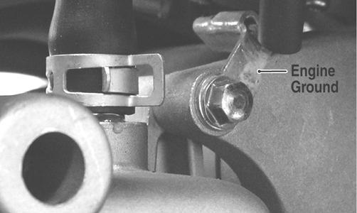
2.Remove the nut securing the positive cable to the starter; then remove the cable from the starter. 3.Remove the two cap screws securing the starter to the crankcase; then remove the starter. Account for an O-ring. INSTALLING 1.Apply a small amount of grease to the O-ring seal on the starter; then install the starter into the crankcase.
Secure with two cap screws making sure the engine ground is secured by the rear cap screws. Tighten to 8 ft-lb.
KC201A
2.Secure the positive cable to the starter with the nut.
Tighten to 8 ft-lb. 3.Connect the battery.
Electronic Control Unit (ECU)
The electronic control unit (ECU) is located above the radiator under the radiator/electrical access panel. NOTE: The ECU is not a serviceable component. If
the unit is defective, it must be replaced.
The ECU is rarely the cause for electrical problems; however, if the ECU is suspected, substitute another ECU of the same part number to verify the suspected one is defective.
Diagnostic Trouble Codes (DTC) can be cleared by following the procedures located in the Diagnostic Trouble Codes (DTC) sub-section in this section.
Regulator/Rectifier
The regulator/rectifier is located under the radiator/electrical access panel. TESTING 1.Start engine and warm up to normal operating temperatures; then connect a multimeter to the battery as follows.
2.Select the DC Voltage position; then connect the red tester lead to the positive battery post and the black tester lead to the negative battery post. 3.Start the engine and slowly increase RPM. The voltage should increase with the engine RPM to a maximum of 15.5 DC volts.
NOTE: If voltage rises above 15.5 DC volts, the reg-
ulator is faulty or a battery connection is loose or corroded. Clean and tighten battery connections or replace the regulator/rectifier. If voltage does not rise, check Voltage (Charging Coil - No Load) in this section. If charging coil voltage is normal, replace the regulator/rectifier.
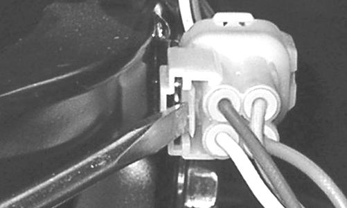
Lights
HEADLIGHTS - RUNNING LIGHTS The connectors are the two 4-pin ones snapped onto the front body panel support. To release the connectors from the frame, press the release tab with a small screwdriver.
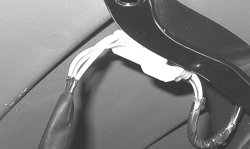
KC224
KC223
Voltage (Headlights) NOTE: Perform this test on the main harness side of
the connectors. Also, the ignition switch must be in the LIGHTS position.
1.Set the meter selector to the DC Voltage position. 2.Connect the black tester lead to the black wire; then connect the red tester lead to the white wire.
3.With the dimmer switch in the LO position, the meter must show battery voltage. 4.Remove the red tester lead from the white wire and connect to the lavender wire.
5.With the dimmer switch in the HI position, the meter must show battery voltage. NOTE: If battery voltage is not shown in any test,
inspect the fuses, battery, main wiring harness, connectors, or the left handlebar switch.
Voltage (Running Lights) 1.Release the wire connector from the frame; then release and separate the connectors. NOTE: Perform this test on the wiring harness side
of the connectors.
2.Connect the black tester lead of the meter to the black wire; then with the tester in the DC Volts position, connect the red tester lead to the brown/black wire.
3.Turn the ignition switch to the LIGHTS position.
The meter must show battery voltage. NOTE: If the meter does not show voltage, inspect
the LIGHTS fuse, battery connections, or troubleshoot the main wiring harness.
TAILLIGHTS - BRAKELIGHTS Voltage (Taillights) NOTE: Perform this test on the main harness side of
the connector. Also, the ignition switch should be in the LIGHTS position.
1.Set the meter selector to the DC Voltage position. 2.Connect the black tester lead to the black wire; then connect the red tester lead to the brown/blue wire.
3.The meter must show battery voltage. NOTE: If the meter does not show voltage, inspect
fuses, wiring harness, connectors, and switches.
Voltage (Brakelights) NOTE: Perform this test on the main harness side of
the connector. Also, the ignition switch should be in the ON position and the brake (either foot pedal or hand lever) must be applied.
1.Set the meter selector to the DC Voltage position. 2.Connect the black tester lead to the black wire; then connect the red tester lead to the green/yellow wire. 3.The meter must show battery voltage. NOTE: If the meter does not show voltage, inspect
bulb, fuses, wiring harness, connectors, and switches.
BACK-UP LIGHTS The connectors are located on the rear frame supports attached by a metal tab. They may be released from the frame by depressing the release with a small screwdriver.
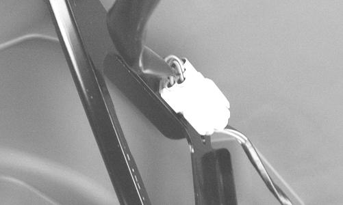
KC279
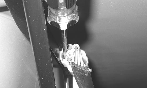
KC280
Voltage 1.Release the wire connectors from the frame; then disconnect the connectors.
NOTE: Perform this test on the main harness side of
the connectors.
2.Connect the black tester lead to the brown/lavender wire; then connect the red tester lead to the lavender/ red wire.
3.Set the tester to DC VOLTS; then turn the ignition switch to the ON position and move the shift lever to the R (reverse) position. The meter must show battery voltage. NOTE: If the meter does not show battery voltage,
use the following procedure to troubleshoot.
4.Remove the black tester lead from the brown/lavender wire and connect to a suitable ground.
A.If the meter shows battery voltage, troubleshoot the gear shift position switch connector or the gear shift position switch.
B.If the meter does not show battery voltage, inspect the LIGHTS fuse, ignition switch, or the main wiring harness.
Ignition Timing
The ignition timing cannot be adjusted; however, verifying ignition timing can aid in troubleshooting other components. To verify engine timing, see Periodic Maintenance.
Diagnostic Trouble Codes (DTC)
If an EFI or related chassis component fails or an out-oftolerance signal is detected by the ECU, a diagnostic trouble code (DTC) will be generated in the ECU and displayed on the LCD. For the first thirty seconds, the LCD will go blank and the DTC will be displayed alternately with a wrench icon or malfunction indicator light (MIL). After thirty seconds, the digital display will return to normal; however, the MIL and DTC will continue to flash. Code List NOTE: Each of the following numerical codes will
have a one-letter prefix of C or P. A “C” prefix denotes a chassis malfunction and a “P” prefix denotes a power train malfunction.
NOTE: Normal malfunction codes are cleared from
the LCD when the component is replaced or the malfunction is corrected; however, intermittent codes must be cleared as noted in the code chart.
C00631 D2 Tilt Sensor Circuit High C00641 D2 Tilt Sensor Circuit Low SG/Open P0107 F2 MAP Sensor Circuit Low SG/Open P0108 F2 MAP Sensor Circuit High SP P0112 F3 IAT Sensor Circuit Low SG P0113 F3 IAT Sensor Circuit High Open P0114¹ F3 IAT Sensor Circuit Intermittent P0116 F4 ECT Sensor Circuit Range/Performance P0117 F4 ECT Sensor Circuit Low SG P0118 F4 ECT Sensor Circuit High Open/SP P0119¹ F4 ECT Sensor Circuit Intermittent P0121 G3 TPS Range/Performance P0122 G3 TPS Circuit Low SG P0123 G3 TPS Circuit High P0219 N/A Engine Over-Speed Condition P0231 J1 Fuel Pump Relay Circuit Low SG/Open P0232 J1 Fuel Pump Relay Circuit High P0233 J1 Fuel Pump Relay Circuit P0264² K4 Cylinder Injector Circuit Low/SG SG P0265² K4 Cylinder Injector Circuit High P0266² K4 Cylinder Injector Balance Open P0336¹ D1/E1 CKP Sensor Synchronization P0337¹ D1/E1 CKP Sensor Circuit SG P0339¹ D1/E1 CKP Sensor Intermittent/Erratic P0480 K2 Fan Relay Control Circuit P0484 K2 Fan Relay Control Circuit High P0485 K2 Fan Relay Control Circuit Low SG/Open P0500 Vehicle Speed Sensor P0508 C4/D3/ Idle Air Control System Circuit Low SG D4/E4 P0509 C4/D4 Idle Air Control System Circuit High Open P0562 L1 System Voltage Low P0563 L1 System Voltage High P0601 N/A ECU Memory Check-Sum Error P0615¹ L3 Starter Relay Circuit P0616 L3 Starter Relay Circuit Low P0617 L3 Starter Relay Circuit High P0630 N/A VIN Not Programmed or Incompatible P0642 A1 Sensor Power Circuit Low P0643 A1 Sensor Power Circuit High P2303² M2 Ignition Coil Primary Circuit Low Open P2304² M2 Ignition Coil Primary Circuit High P2531 A4 Ignition Switch Circuit Low P2532 A4 Ignition Switch Circuit High U0155 B1/C1 LCD Gauge Communication Lost *FUEL *Tilt Sensor Activation Operator-Code
OFF
HighSignal Level too High (Possible Short-to-Battery (+))
Low Signal Level too Low (Possible Short-to-Ground or Shortto-Chassis)
SG Possible Short-to-Ground or Short-to-Chassis
OpenOpen-Circuit (Possible Broken-Wire or No-Connection) 1 These codes cleared by one complete power-cycle only (key-off, key-on) 2 These codes cleared by one complete starting-cycle only (key-off, key-on, start, key-off, key-on)
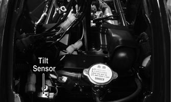
Tilt Sensor
The tilt sensor is located above the radiator under the radiator/electrical access panel.
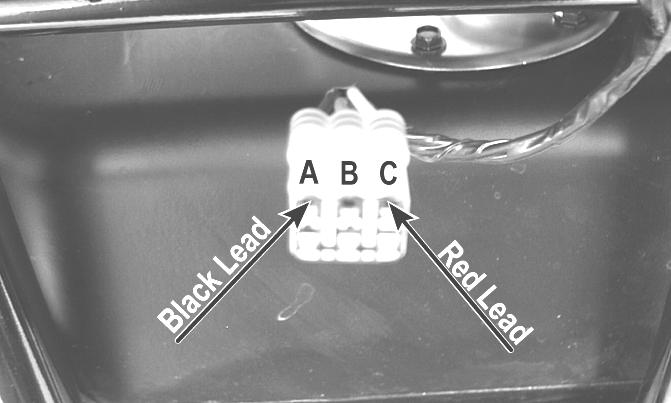
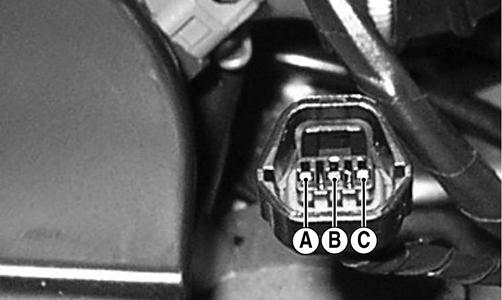
SUPPLY VOLTAGE 1.Disconnect the three-wire connector from the sensor; then select DC Voltage on the multimeter and connect the red tester lead to the (C) pin and the black tester lead to the (A) pin.
! WARNING
Incorrect installation of the tilt sensor could cause sudden loss of engine power which could result in loss of vehicle control resulting in injury or death.
CAUTION
Do not drop the tilt sensor as shock can damage the internal mechanism.
CD706A
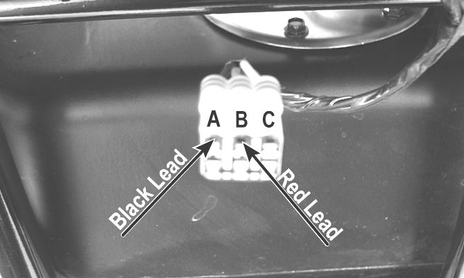
2.Turn the ignition switch to the ON position. The multimeter should read approximately 5 DC volts. If correct voltage is not indicated, check the 30-amp main and 10-amp ignition fuses, wiring harness, or the ignition switch. 3.Remove the red tester lead and connect to the (B) pin. The multimeter should read approximately 0.5
DC volts. If the specified voltage is not indicated, check wire connections at the ECU or substitute another ECU to verify the test.
CD706B
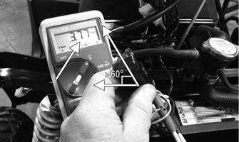
OUTPUT VOLTAGE NOTE: Needle adapters or a “break-out” harness
will be required on the multimeter leads as the following tests are made with the sensor connected.
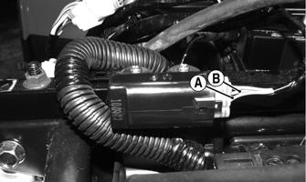
1.Connect the three-wire plug to the sensor; then remove the mounting screws securing the sensor to the frame.
KC466F
2.Install the needle adapters to the multimeter leads; then select DC Voltage on the multimeter. 3.Connect the red tester lead to the blue/brown wire (B) and the black tester lead to the pink/black wire (A); then turn the ignition switch ON and observe the meter. The meter should read 0.3-1.5 DC volts.
KC416A
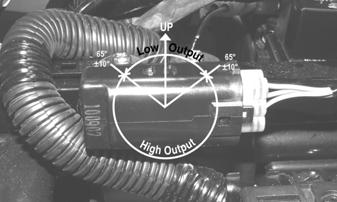
4.Tilt the sensor 60° or more to the left and right observing the meter. The meter should read 3.0-7.0
DC volts after approximately one second in the tilted position. If the meter readings are not as specified, the tilt sensor is defective.
KC416B
Throttle Position Sensor (TPS)
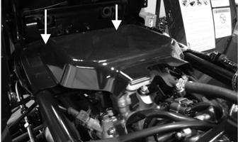
INSPECTING 1.Remove the left-side engine cover; then disconnect the three-wire TPS connector plug.
PR544
NOTE: Prior to testing the TPS, inspect the three-
wire plug connector on the main harness and the three-pin plug on the TPS for contamination, broken pins, and/or corrosion.
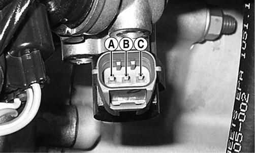
2.Make sure the ignition switch is in the OFF position; then select the DC Voltage position on the meter. 3.Connect the black tester lead to terminal B and the red tester lead to terminal A. Turn the ignition switch to the ON position. The meter should read approximately 5.0 DC volts.
PR538A
NOTE: If the meter does not read as specified,
check for poor connections at the ECU or open/broken wires in the wiring harness.
CAUTION
Always make sure the ignition switch is in the OFF position before disconnecting the ECU.
4.Turn the ignition switch to the OFF position. 5.Select the OHMS position on the meter; then perform the following resistance tests on the TPS.
A.Pin (B) to ground - infinity (open circuit).
B.Pin (A) to pin (B) - approximately 1.22k ohms (throttle closed).
C.Pin (A) to pin (B) - approximately 4.5k ohms (throttle full-open).
D. Pin (A) to pin (C) - approximately 5.5k ohms.
PR535A
NOTE: If any meter reading is not as specified,
replace or adjust the TPS (see INSTALLING/ADJUSTING in this sub-section).
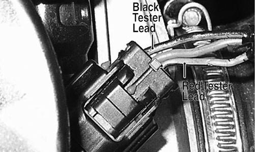
6.Connect the positive lead to the battery; then connect the negative lead. 7.Connect the main harness TPS connector to the TPS; then using MaxiClips, connect the black tester lead to the black/green wire and the red tester lead to the green/black wire.
PR546A
8.Select the DC Voltage position on the meter and turn the ignition switch to the ON position. The meter should read approximately 4.5 DC volt with the throttle closed and approximately 1.5 DC volts with the throttle in the full-open position. NOTE: If the meter readings are as specified, check
the main harness connector at the ECU main harness wiring. If the meter readings are not as specified, replace the TPS and adjust to specifications (see INSTALLING/ADJUSTING in this sub-section).
CAUTION
Always make sure the ignition switch is in the OFF position before disconnecting the ECU.
9.Verify all malfunction codes are closed after servicing is complete (see Diagnostic Trouble Codes (DTC) in this section). REMOVING 1.Remove the left-side engine cover; then disconnect the three-wire TPS connector plug.
PR544
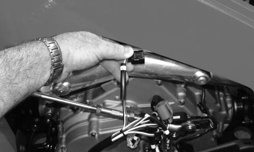
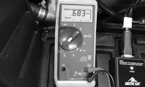
2.Remove the screw securing the TPS to the throttle body and remove the TPS. INSTALLING/ADJUSTING 1.Place the TPS into position on the throttle body and secure with the screw. Do not tighten at this time. 2.Connect the TPS Multi-Analyzer Harness connector #8 to the TPS; then connect the harness to the TPS
Analyzer Tool.
FI672
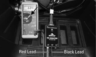
3.Using a multimeter, connect the black tester lead to the black socket (GND) on the analyzer and the red tester lead to the white socket (VAR); then select the
Voltage position.
FI673A
4.Adjust the TPS until a reading of 0.68 DC volts is obtained; then tighten the screw securely. Open and close the throttle and determine the reading returns to 0.68 DC volts. Readjust as necessary.
FI674
5.Disconnect the harness from the analyzer; then disconnect the harness from the TPS and reconnect the
TPS main harness connector.
6.Tighten the mounting screws securely.
Troubleshooting
Problem: Spark absent or weak Condition Remedy
1. Ignition coil defective 1.Replace ignition coil 2. Spark plug defective 2.Replace plug 3. Alternator defective 3.Replace magneto 4. ECU defective 4.Replace ECU 5. Pick-up coil defective 5.Replace pick-up coil
Problem: Spark plug fouled with carbon Condition Remedy
1. Gasoline incorrect 1.Change to correct gasoline 2. Air cleaner element dirty 2.Clean element 3. Spark plug incorrect (too cold) 3.Replace plug 4. Valve seals cracked - missing 4.Replace seals 5. Oil rings worn - broken 5.Replace rings
Problem: Spark plug electrodes overheat or burn Condition Remedy
1. Spark plug incorrect (too hot) 1.Replace plug 2. Engine overheats 2.Service cooling system 3. Spark plug loose 3.Tighten plug
Problem: Alternator does not charge Condition Remedy
1. Lead wires/connections shorted - loose - open 1.Repair - replace - tighten lead wires 2. Stator coils shorted - grounded - open 2.Replace stator coils 3. Regulator/rectifier defective 3.Replace regulator/rectifier
Problem: Alternator charges, but charging rate is below the specification Condition Remedy
1. Lead wires shorted - open - loose (at terminals) 1.Repair - tighten lead wires 2. Stator coils grounded - open 2.Replace stator coils 3. Regulator/rectifier defective 3.Replace regulator/rectifier 4. Battery defective 4.Replace battery
Problem: Alternator overcharges Condition Remedy
1. Internal battery short circuited 1.Replace battery 2. Regulator/rectifier damaged - defective 2.Replace regulator/rectifier 3. Regulator/rectifier poorly grounded 3.Clean - tighten ground connection
Problem: Charging unstable Condition Remedy
1. Lead wire intermittently shorting 1.Replace lead wire 2. Alternator internally shorted 2.Replace stator coil 3. Regulator/rectifier defective 3.Replace regulator/rectifier
Problem: Starter button inoperative Condition Remedy
1. Battery charge low 1.Charge - replace battery 2. Switch contacts defective 2.Replace switch 3. Starter motor defective 3.Replace starter motor 4. Starter relay defective 4.Replace relay 5. Emergency stop - ignition switch off 5.Turn on switches 6. Wiring connections loose - disconnected 6.Connect - tighten - repair connections
Problem: Battery “sulfation” (Acidic white powdery substance or spots on surfaces of cell plates) Condition Remedy
1. Charging rate too low - too high 1.Repair charging system 2. Battery run-down - damaged 2.Replace battery 3. Electrolyte contaminated 3.Replace battery
Problem: Battery discharges too rapidly Condition Remedy
1. Electrolyte contaminated 1.Replace battery 2. Charging system not charging 2.Check alternator - regulator/rectifier - circuit connections 3. Battery overcharged - damaged 3.Replace battery - correct charging system 4. Battery short-circuited 4.Replace battery
Problem: Battery polarity reversed Condition Remedy
1. Battery incorrectly connected 1.Reverse connections - replace battery - repair damage