1 minute read
REAR AXLE DIFFERENTIAL CARRIER


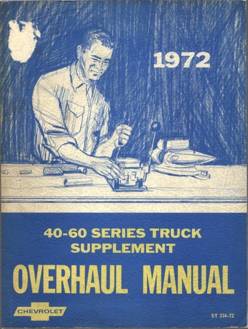
Fig. 10E~Assem bling Cover and Pressure Plate
vehicle procedure using alignment arbor as a gauge plate.
NOTE: Do not place bending load on fro n t pressure plate drive straps.
A d ju stin g Levers
While no wear adjustment is needed because of the coil spring design, it is imperative that the clutch release levers are each set to exactly the same height at the time of manufacture or rebuild to insure uniform clutch application. To obtain exactly the same adjustment at each release lever, use gauge plate J-1048 and release lever height gauge J-6456 as follows:
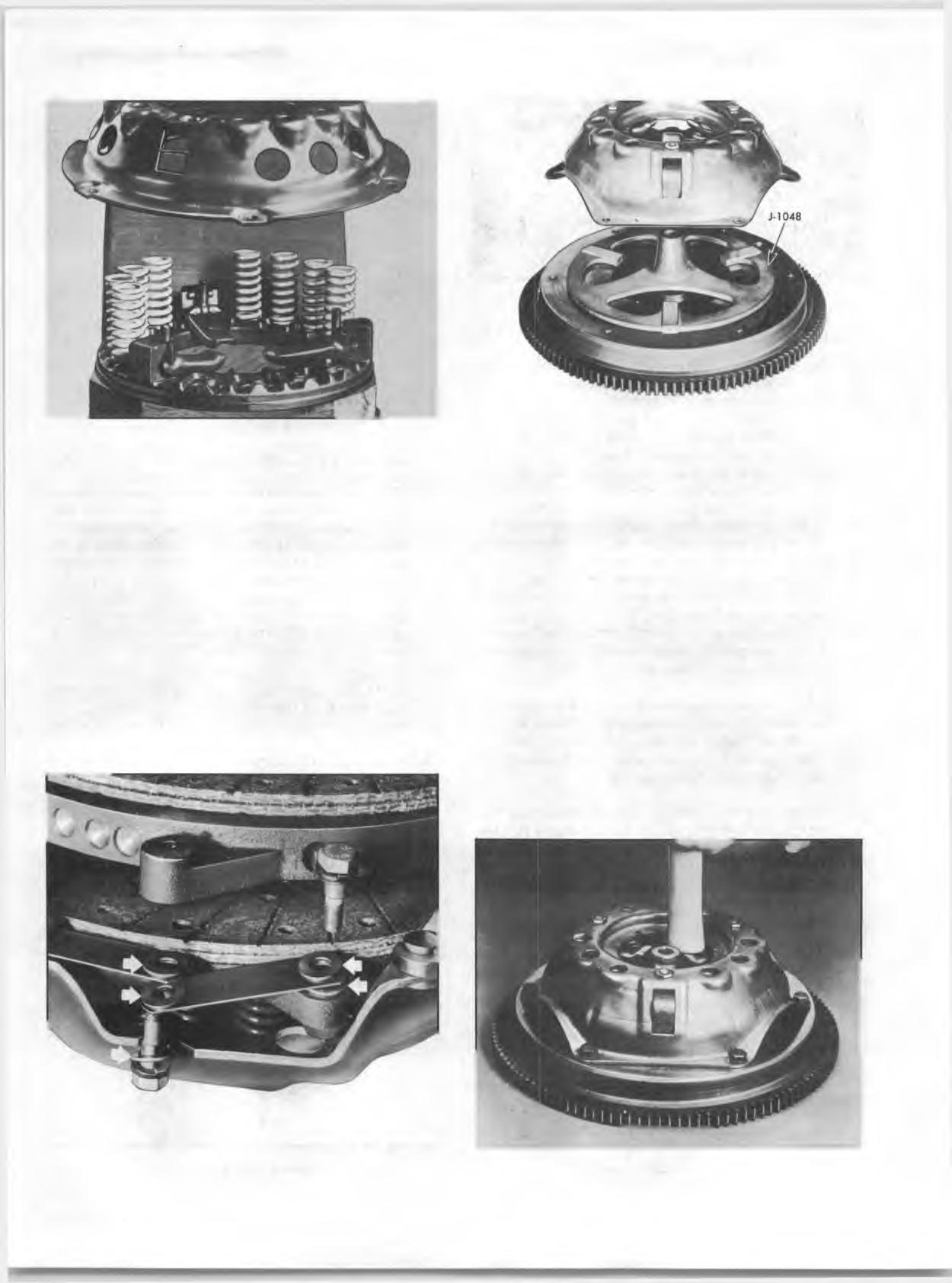
Fig. 12E~Gauge Plate Position (Typical)
1. Place gauge plate J-1048 (fig. 12E) on the flywheel in position normally occupied by driven plate.
NOTE: It is recommended th at a spare flywheel be obtained so th a t this operation may be performed at the bench.
2. Bolt cover on flywheel with gauge plate center.
NOTE: On assemblies w ith three levers, the three fla t machined lands of the gauge plate must be located directly under the levers. On the larger 13" clutch w ith four levers, any position is satisfactory.
3.
4. Depress each lever several times with a hammer handle to settle all parts into working position. Position height gauge J-6456 on the hub of the gauge plate and the bearing surface of one lever (fig. 13E). Turn adjusting nut until lever is flush with proper step of height gauge. Adjust remaining levers in same manner. The height gauge (insert) has three steps for use
Fig. 11E --D rive S trap Assem bly Fig. 13E--Depressing Lever