6 minute read
SERIES 4 0 - 6 C H E V R O L E T TR U CK S


S E C T I O N 7
CLUTCH ES A N D T R A N S M IS S IO N S
CONTENTS
Two Plate Coil Spring Clutch .............................................. 7-1 5-Speed Clark Transmission (Model 325and 327) .......... 7-35 5-Speed New Process Transmission (Model 540 and 542).. 7-5 Auxiliary 4-Speed Transmission (Spicer 6 0 4 1 )...............7-47 5-Speed Spicer Transmission (5000 Series) ....................... 7-12 Auxiliary 4-Speed Transmission (Spicer 7 0 4 1 )...............7-51 5-Speed Clark Transmission (Model 282 and 2 8 5 )............. 7-23 AT-475 Transmission ........................................................7-58 Special Tools ...................................................................... 7-102
T W O PLATE C O IL S P R I N G CLUTCH
INDEX
Disassembly.................................................................... 7-1 Inspection ....................................................................... 7-2 Assembly......................................................................... 7-3 Pilot Bearing Replacement.......................................... 7-5
D isa sse m b ly
1. With assembly (on floor or bench) resting on front pressure plate side, remove 4 drive strap-to-front pressure plate bolts and the washers. 2. Lift the cover and rear pressure plate off front pressure 4. plate and rear driven disc, turn it over and remove drive strap bolt and strap from rear pressure plate. Place the cover assembly on the bed of an arbor or drill press with a block under the pressure plate so arranged that the cover is left free to move down. Place a block or bar across the top of the cover with the
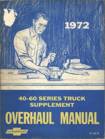
1. Flywheel 2. Driven Discs 3. Front Pressure Plate 4. Rear Pressure Plate 5. C lutch Cover 6. Coil S pring 7.
8 . 9. T h ro w o u t Bearing Release Yoke Release Lever
Fig. 1E-2-Plate Clutch C ross-S ection 10 .
1 1 . 1 2 . Anti-R attle Spring A d ju stin g Nut l-B olt
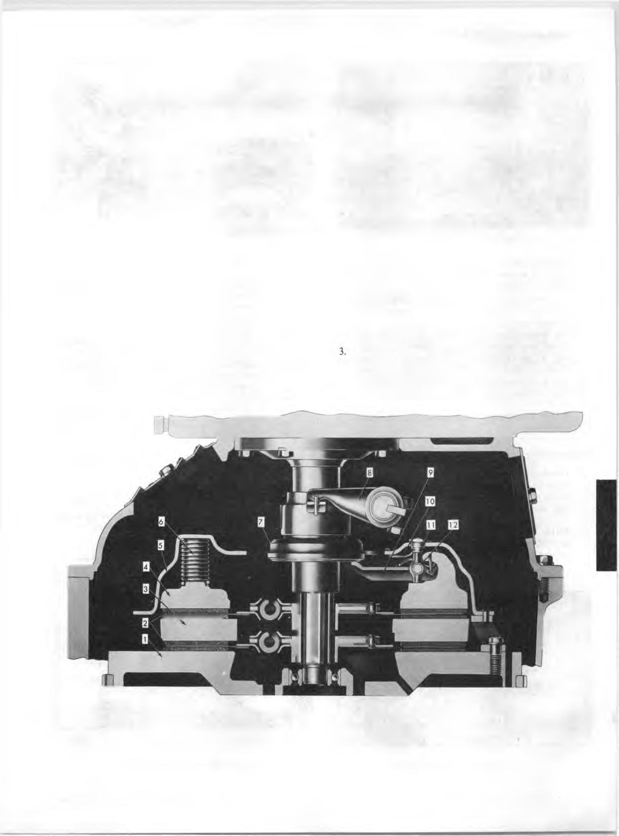
Fig. 2E-C om pressing Clutch
spindle. Hold compressed while the adjusting nuts are removed as shown in Figure 2E, then slowly release pressure to prevent springs flying out. 5. Lift off cover and all parts will be available for inspection. Note carefully the location of all parts including arrangement of springs, see (fig. 3E). 6 . To remove levers grasp lever and eyebolt between thumb and fingers as shown in Figure 4E, so that inner end of lever and upper end of eyebolt are close together, keeping eyebolt pin seated in its socket in lever. 7. Lift strut over ridge on end of lever, (fig. 5E). 8 . Lift lever and eyebolt off pressure plate.

NOTE: It is im portant to replace all parts which show wear.
Inspection
1. Check drive straps for looseness at the clutch cover and evidence of looseness at pressure plate bolt holes. 2. Wash all parts, except driven disk and throwout bearing, in cleaning solvent.
NOTE: The throw out bearing is permanently packed w ith lubricant and should not be soaked in cleaning solvent as this w ill dissolve the lubricant.
3. Inspect pressure plate and flywheel for scores on the
1. Release Lever 2. Eyebolt 3. S trut
Fig. 4E~Removing Levers (Step 1)
contact surfaces. Use a straight-edge and check for flatness of contact surfaces. 4. Check throwout bearing for roughness and free fit on the sleeve of the transmission clutch gear bearing retainer. Replace retainer if rough. 5. Inspect clutch disc for worn, loose or oil soaked facings, broken springs, loose rivets, etc. Replace if necessary. 6 . Examine splines in hub and make sure they slide freely on splines of transmission clutch shaft. If splines are worn, the clutch disc or clutch gear should be replaced as necessary. 7. Inspect clutch fork ball socket and fingers for wear and ball retaining spring for damage. Spring should hold fork tightly to ball stud.
NOTE: Ball spring on fo rk may be bent in toward fork if necessary.
8 . Inspect ball stud for wear. Replace if scored. 9. Check run out of transmission pilot hole in clutch housing by removing a flywheel bolt and installing a dial indicator. The run out should be within .000-.015". 10. Lubricate ball stud before reassembly.
Fig. 3E--Disassembly o f Clutch 1. Release Lever 2. Eyebolt 3. S trut
Fig. 5E-R em oving Levers (Step 2)
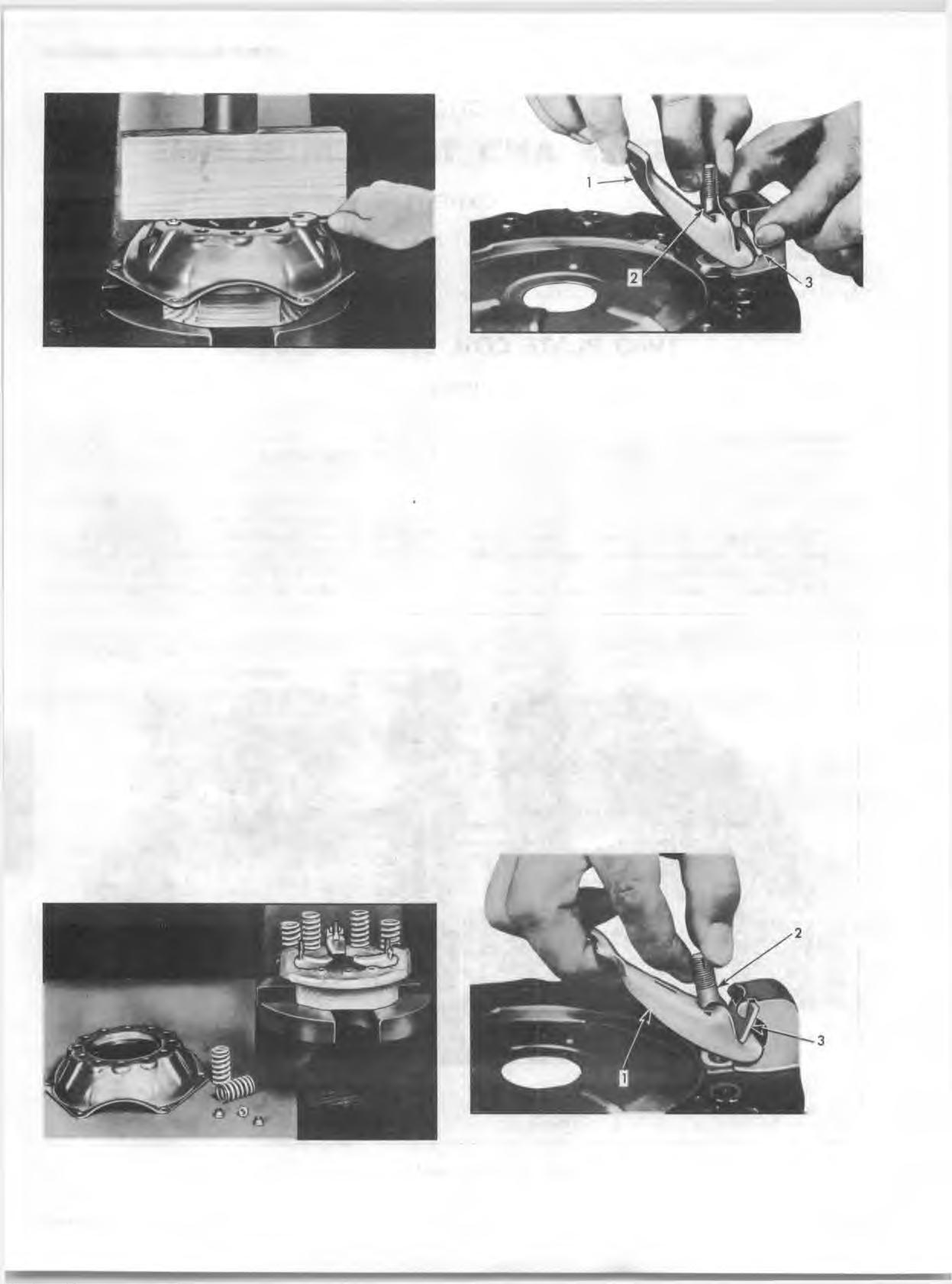
Fig. 6E~G reasing Lug
A ss e m b ly

1. Lay the pressure plate on the block in the press and coat the lugs with a thin film of approved lubricant such as lubriplate as shown in Figure 6 E. 2. Assemble lever, eyebolt and pin, holding eyebolt and lever as close together as possible and with the other hand grasp strut as shown in figure 7E. 3. Insert Strut in the slots in the pressure plate lug, drop slightly and tilt the lower edge until it touches vertical milled surface of lug. 4. Insert lower end of eyebolt in hole in pressure plate. The short end of the lever will then be under the hook of the pressure plate and near the strut, (fig. 5E). 5. Slide the strut upward in the slots of the lug, lifting it over the ridge on the short end of the lever and drop it into the groove in the lever, (fig. 4E). 6 . Assemble the pressure springs, on the small bosses of the pressure plate in accordance with Figure 8 E in order to retain original balance.
NOTE: If there are spaces for more springs than specified for the particular assembly, or if tw o different colors of springs are used, Figure 8E shows the proper sequence. It is very important th a t each group be arranged in like sequence.
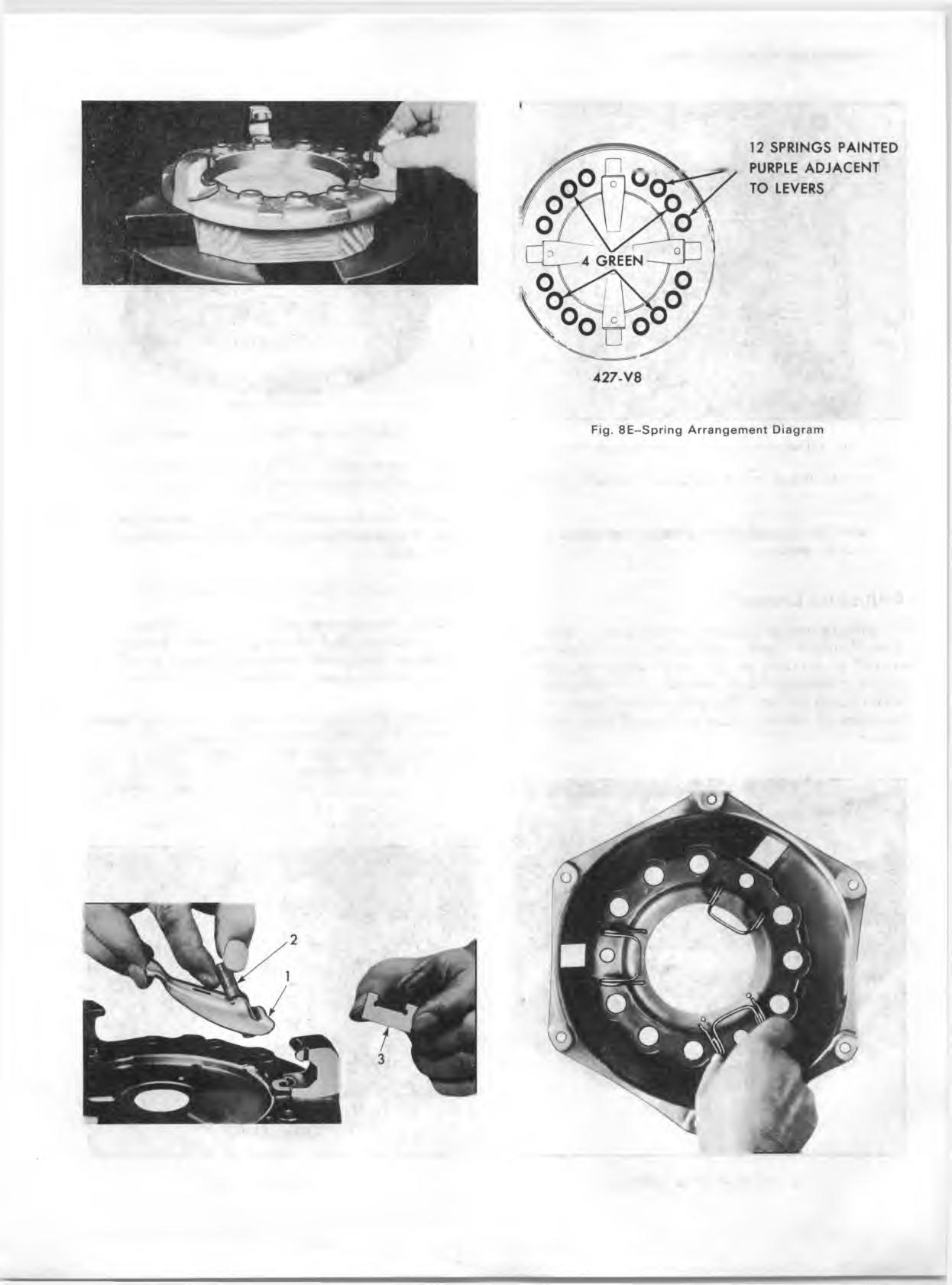
7. Assemble anti-rattle springs in cover as shown in Figure 9E. The spring to the left is in operating position. 8 . Lower the cover on top of the assembled parts, (fig. 10E) being sure that the anti-rattle springs are in correct position and also that the punch marks made before
dismantling are matched to insure retaining the original balance. 9. Place a bar across the cover and slowly compress, guiding the holes in the cover over the pressure plate lugs and all springs into their spring seats in the cover. 10. Assemble adjusting nuts on the eyebolts and screw them down until their tops are flush with the tops of the eyebolts. Slowly release pressure of spindle and remove cover assembly from press. 11. Place cover assembly on bench with pressure plate side up and install drive straps, bolts and washers (special and lock) as shown in Figure HE. 12. Place one driven plate on rear pressure plate with hub up, then set front pressure plate on driven plate (with drive boss flush side toward rear driven plate). 13. Install drive strap to front pressure plate bolts as shown in Figure HE. 14. Adjustment of the fingers is done during installation to
1. Release Lever 2. Eyebolt 3. S trut
Fig. 7E— Installing Lever Fig. 9E --lnstalling Anti-R attle Spring