13 minute read
MAINTENANCE SERVICE

SCHEDULED MAINTENANCE UNDER SEVEiRE USAGE CONDITIONS
The maintenance items should be performed according to the following table:
Maintenance Item Service to be Performed
Mileage Intervals Kilometers in Thousands (Miles in Thousands) Severe Usage Conditions

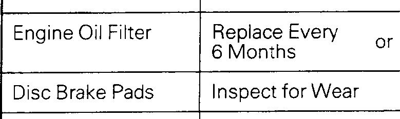
IEngine Oil Change Every or 3 Months (:z:.:a::I
Rear Drum Brake Linings and Rear Wheel Cylinders Inspect for Wear and Leaks 1 Severe usage conditions
A-Driving in dusty conditions - - B- I railer towing or police. taxi, or commercial type operation
C-Extensive idling
D-Short trip operation at freezing temperatures (engine not thoroughly warmed up) More Frequently
Every 4,800 km

(3,000 miles)
Every 9,600 km (6,000 miles)
More Frequently
More Frequently
/xlxlx/xI I I1 IxIxlxIxI I I>(
1x1 I I I
I I I I I
1x1
I I
Ix1 I I I lx/
E-Driving in sandy areas - -.. F-Dnvlng In salty areas G-More than 50% operation in heavy city trafic during hot weather above 32°C (90°F)
MAINTENANCE SERVICE
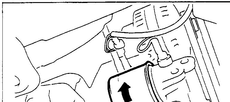
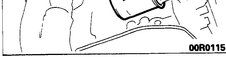
1. FUEL SYSTEM (Tank, Lines, Connections and
Fuel Tank Filler Tube Cap) (Check for leaks)/2.
FUEL HOSES (Check for leaks or damagekOOSnOB.
1. Check for damage or leakage in the fuel lines and connections and looseness of the fuel tank filler tube cap.
2. Inspect the surface of fuel hoses for heat and mecha
nicall damage. Hard and brittle rubber, cracking, checking, tears, cuts, abrasions and excessive swelling indicate deterioration of the rubber. 3. If the fabric casing of the rubber hose is exposed by cracks and abrasions in the fuel system, the hoses should be changed.
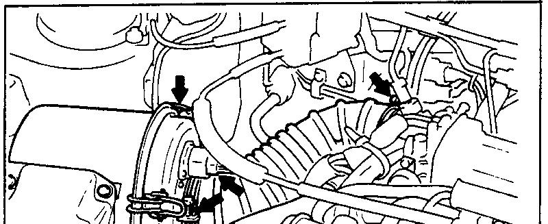
3. AIR CLEANER ELEMENT (Replace) MMlSAKH
The air cleaner element will become dirty and loaded with dust during use, and the filtering effect will be substantially reduced. Replace it with a new one.
<Non-Turbo>
(1) Loosen the clamp coupling the air intake hose and the air cleaner cover, and separate the hose. (2) Disconnect the volume air flow sensor connectors. (3) Unclamp the air cleaner cover clip. (4) Lifting the air intake hose, remove the air cleaner cover.
Caution
The air cleaner cover should be removed carefully, because it includes the volume air flow sensor. /
gauge (5) Remove the air cleaner element. (6) Set a new air cleaner element and install the air cleaner
I hose


,I

Plug gap cover.
Measurement rection
01 I f
0110182
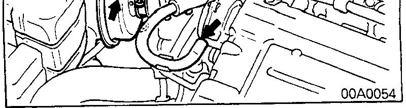
<Turbo>
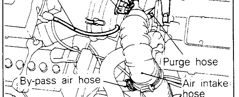
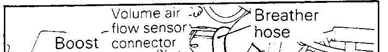
(1) Disconnect the volume air flow sensor connector. (2) Disconnect the breather hose, purge hose, by-pass air hose and boost hose connections. (3) Remove the air intake hose on the air cleaner cover side and then move the air intake hose to the front of the air cleaner body. (4) Unclamp the air cleaner cover.
Caution Care must be taken when removing the air cleaner cover, because the volume air flow sensor is attached.
(5) Take out the air cleaner element. (6) Check the air cleaner element for dirt or clogging; if necessary, clean by using compressed air. (7) Replace the air cleaner element if the dirt or clogging is serious. (8) Insert the element into the air cleaner body and install the air cleaner cover. (9) Install the air intake hose. (10)Connect the breather hose, purge hose, by-pass air hose and boost hose. (11 )Connect the volume air flow sensor connector.
4. SPARK PLUGS (Replace)
h%OSAOFa
1. Spark plugs must spark properly to assure proper engine performance and reduce exhaust emission level.
Therefore, they should be replaced periodically with new ones. 2. The new plugs should be checked for the proper gap.
Spark plug gap: <Non-Turbo> 1.0-1.1 mm (.039-.043 in.) <Turbo> 0.7-0.8 mm (.028-.031 in.)
3. Install the spark plug and tighten to 20-30 Nm (15-21 ftlbs.).
5. TIMING BELT (Replace) moossAsa
Replace the belt with a new one periodically to assure proper engine performance.
For disassembly and reassembly procedures, refer to
GROUP 11 -Service Adjustment Procedures.
L!

-1
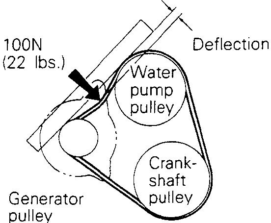
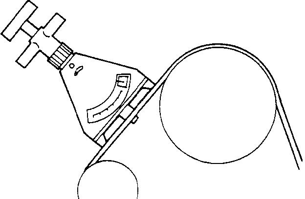
6. DRIVE BELT (For Water Pump and Generator) (Inspect for tension)
MOOSBBN
(1) Place straight edge as shown in the illustration. (2) Measure the deflection with a force of 100 N (22 Ibs.) applied to belt mid-point between water pump pulley and generator pulley. If the standard value is not obtained, make adjustment.
Standard value: 9.0-l 1.5 mm (.354-.453 in.)
6COOO9
(3) Use a tension gauge to check the belt tension. If the standard value is not obtained, make adjustment.
When tension gauge is used, the tension may be measured between any two pulleys.
Standard value: 250-500 N (55-110 Ibs.)
6COO39
OlR0344
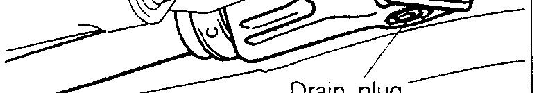
7. ENGINE OIL (Change)
MOOSAABc
Always use lubricants which conform to the requirements of the API classification “For Service SG” or “For Service SG/CD” when available, and have the proper SAE grade number for the expected temperature range. Never Lose nondetergent or straight mineral oil. (1) After warming up the engine, remove the oil filler cap. (2) Remove the drain plug to drain the engine oil. (3) Replace the drain plug gasket with a new one and tighten the drain plug. (4) Supply new engine oil through the oil filler.
Engiine oil capacity:
Items
Oil pan Models built up to April 1992 SOHC
DOHC
1 Oil filter Models built from May 1992
Oil cooler (clnly models with turbo) Engine oil capacity 3.5 dm3 (3.7 qts.) 4.0 dm3 (4.2 qts.) 4.0 dm3 (4.2 qts.) 0.3 dm3 (l/2 qt.) 0.3 dm3 (I/2 qt.)
(5) Start and run the engine a few minutes. (6) Stop the engine and check the engine oil level.
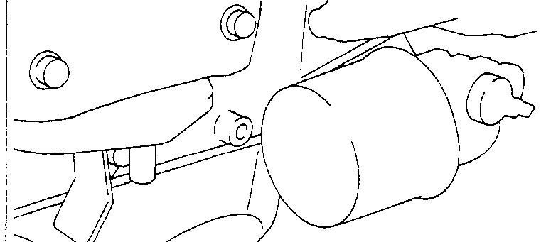
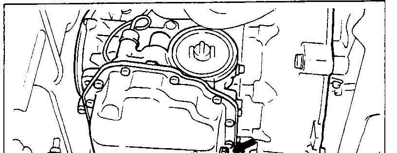
8. ENGINE OIL FILTER (Change)
MOOSABG
The quality of replacement filters varies considerably. Only high quatlity filters should be used to assure most efficient service. Genuine oil filters require that the filter is capable of withstarlding a pressure of 256 psi are high quality filters and are recommended as follows:
Oil Filter Part No.
Mitsubishi Genuine Parts: MD135737, MD136466
OSPOO26 1
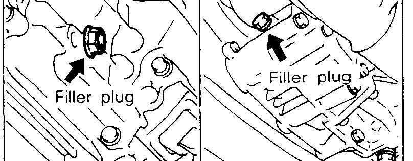
ENGINE OIL FILTER SELECTION
This vehicle is equipped with a full-flow, throw-away oil filter. The same type of replacement filter is recommended as a replacement filter for this vehicle. It is possible, particularily in cold weather, that this vehicle may develop high oil pressure for a short duration. You should be sure that any replacement filter used on this vehicle is a high-quality filter and is capable of withstanding a pressure of 256 psi (manufacturer’s specifications) to avoid filter and engine damage. The following is a high-quality filter and is strongly recommended for use on this vehicle : Mitsubishi Engine Oil Filter Part No. MD1 35737 or MD1 36466. Any replacement oil filter should be installed in accordance with the oil filter manufacturer’s installation instructions. (1) Remove the engine oil filler cap. (2) Remove the engine oil drain plug, and drain out the engine oil. (3) Remove the engine oil filter by using the oil filter
(4) GLr!he oil filter mounting surface of the oil filter bracket.
09A.0024
(5) Coat engine oil to the O-ring of new oil filter. (6) Screw in the oil filter with hand until it touches the surface of the flange and then tighten it with the filter wrench, etc.
l 0
For MD135737: One full turn or 14 Nm (loft. Ibs.) For MD136466: 3/4 turn or 17 Nm (12 ft. Ibs.) (7) Supply engine oil. (8) Start and run engine and check for engine oil leaks. (9) After stopping engine, check oil level and replenish as necessary.
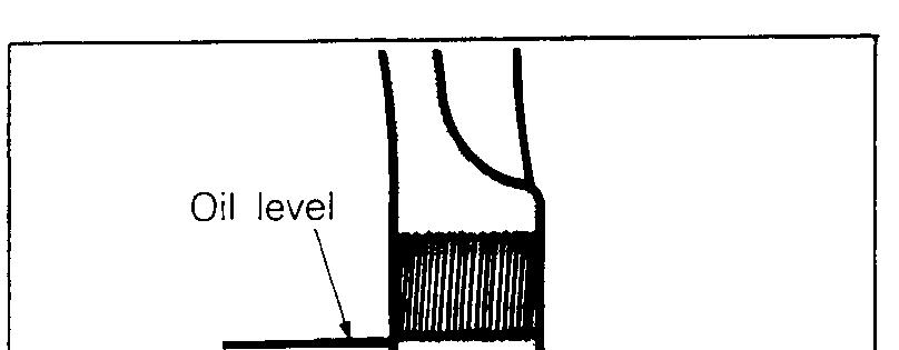
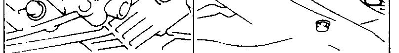
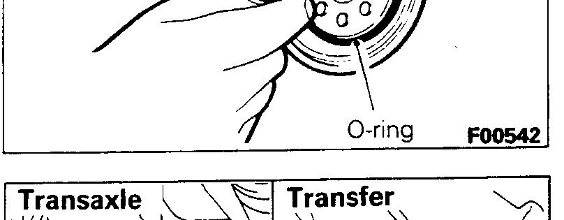
9. MANUAL TRANSAXLE (Inspect oil level)
MOO66CE
Inspect each component for evidence of leakage, and check the oil level by remaining the filler plug. If the oil is contaminated, it is necessary to replace it with new oil. I. With the vehicle parked at a level place, remove the filler plug and check to be sure that the oil level is up to the lower edge of the filler plug hole. 2. Check to be sure that the transmission oil is not noticeably dirty, and that it has a suitable viscosity.
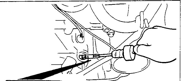
1 O.AUTOMATIC TRANSAXLE MOOSSDA
Inspect fluid level
1. Drive until the fluid temperature reaches the usual ternperature [70-80°C (160- 18O”F)I. 2. Plaice vehicle on level floor. 3. Move selector lever sequentially to every position to fill torque converter and hydraulic circuit with fluid, then place lever in “N” Neutral position. This operation is necessary to be sure that fluid level check is accurate. 4. Before removing dipstick, wipe all dirt from area around dipstick. Then take out the dipstick and check the condition of the fluid.
The transaxle should be overhauled under the following conditions. l If there is a “burning” odor. l If the fluid color has become noticeably blacker. l If there is a noticeably great amount of metal particles in the fluid. 5. Chleck to see if fluid level is in “HOT” range on dipstick.
If fluid level is low, add ATF until level reaches “HOT” range. LO\N fluid level can cause a variety of conditions because it allows pump to take in air along with fluid. Air trapped in hydraulic circuit forms bubbles which make fluid spongy. Therefore, pressures will be erratic.
Improper filling can also raise fluid level too high. When transaxle has too much fluid, gears churn up foam and cause same conditions which occur with low fluid level, resulting in accelerated deterioration of ATF.
In either case, air bubbles can cause overheating, fluid oxidation, which can interfere with normal valve, clutch, and servo operation. Foaming can also result in fluid escaping from transaxle vent where it may be mistaken for a leak. 6. Be sure to examine fluid on dipstick closely.
Chaqge fluid
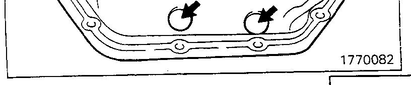
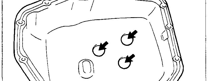
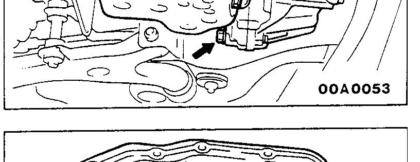
Drain tlhe fluid and check whether there is any evidence of contamination. Replenish with new fluid after the cause of any contamination has been corrected. (1) Rernove drain plugs to let fluid drain. (2) Rernove the oil pan. (3) Check the oil filter for clogging and damage and replace if necessary. (4) Clean the inside of oil pan and 5 magnets. (5) Attach the five magnets to the concave part of the oil pan. (6) Clean both gasket surfaces of transaxle case and oil pan. (7) Install oil pan with new gasket and tighten oil pan bolts to IO-I 2 Nm (7.5-8.5 ftlbs.) (8) Tighten drain plug with gasket to 30-35 Nm (22-25 ft.lbs.). (9) Supply 4 dm3 (4.23 qts.) of specified ATF into case through dipstick hole. [Total quantity of ATF required is 6.1 dm3 (6.45 qts.).
Actually however, approx. 4.5 dm3 (4.76 qts.) of fluid car1 be replaced because rest of fluid remains in torque converter.] 1
1 TSB Revision
OOA0051

(1O)Star-t engine and allow to idle for at least two minutes.
Then, with parking brake on, move selector fever momentarily to each position, ending in “N” Neutral position. (11)Add sufficient ATF to bring fluid level to lower mark.
Recheck fluid level after transaxle is at normal Operating temperature.
Fluid level should be between upper and lower marks of
“HOT” range, Insert dipstick fully to prevent dirt from entering transaxle.
11 .ENGINE COOLANT (Change) MOOSEEAC
Check the cooling system parts, such as radiator, heater, and oil cooler hoses, thermostat and connections for leakage and damage.
CHANGE COOLANT
1. Remove the radiator cap. 2. Loosen the drain plug to drain the coolant. 3. Drain the coolant from the reserve tank. 4. After draining the coolant, tighten the drain plug securely. 5. Supply the coolant into the radiator until it is filled up to its filler neck. 6. Supply the coolant into the reserve tank. 7. After warming the engine until the thermostat opens, remove the radiator cap and check the coolant level. 8. Supply the coolant into the radiator until it is filled up to its filler neck, and install the radiator cap securely. 9. Fill the reserve tank with coolant up to the “FULL” line.
1
14K512
12.DISC BRAKE PADS (Inspect for wear)
MWSBFA
Check for fluid contamination and wear. Replace complete set of pads if defective.
Caution The pads for the right and left wheels should be reDlaced at the same time. Never “split” or intermix brkke pad sets. All four pads must be replace as a complete set. Thickness of lining (A)
Limit: 2.0 mm (.08 in.)
13.REAR DRUM BRAKE LININGS AND REAR
WHEEL CYLINDERS (Inspect for wear and
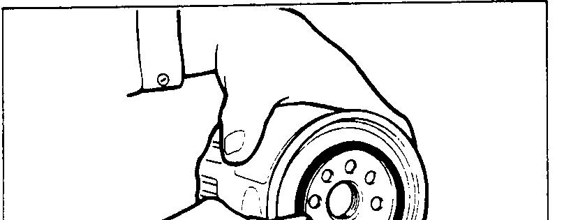
leaks) MOOSBGB 1. Remove the brake drum and check the thickness of brake shoe lining for wear. Check the automatic brake adjusting system by hand to see if it operates smoothly.
Also see if the gears are in proper mesh with each other. To assure smooth functioning, apply a very thin coat of multipurpose grease to the friction surface of adjuster and link shaft.
14KO24

OOA0186 2. Inspect the wheel cylinder boots for evidence of a brake fluid leak. Visually check the boots for cuts, tears or heat cracks. (A slight amount of fluid on the boot may not be a leak, but may be preservative fluid used at assembly.) Checking the Brake Shoes for Wear.
Thiclkness of lining (B) Limit: 1.0 mm (.04 in.)
14.BRAKEI HOSES (Check for deterioration or
leaks) MOOSBHA
Inspection of brake hoses and tubing should be included in all brake service operations. The hoses should be checked for: 1. Correct length, severe surface cracking, pulling, scuffing or worn spots. (If the fabric casing of the hoses is exposed by cracks of abrasion in the rubber hose cover, the hoses should be replaced. Eventual deterioration of hose may occur with possible bursting failure.) 2. Faulty installation, casing twisting or interference with wheel, tire of chassis.
15.BALL ,IOINT AND STEERING LINKAGE SEALS
(Inspect for grease leaks and damage) MOOSBJAa
I, These components, which are permanently lubricated at the factory, do not require periodic lubrication.
Damaged seals and boots should be replaced to prevent leakage or contamination of the grease. 2. Inspect the dust cover and boots for proper sealing, leakage and damage. Replace them if defective.
16.DRIVE SHAFT BOOTS (Inspect for grease leaks
and damage) MOOSWAb
1. The.se components, which are permanently lubricated at the factory, do not require periodic lubrication.
Damaged boots should be replaced to prevent leakage or contamination of the grease. 2. Inspect the boots for proper sealing, leakage and damage. Replace it if defective.
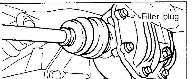
17.REAR AXLE (Inspect oil level)-AWD
MOOSBPQ
Remove the filler plug and inspect the oil level at bottom of filler hole. If the oil level is slightly below the filler hole, it is in satisfactory condition.
18.EXHAIJST SYSTEM (CONNECTION PORTION OF MUFFLER, PIPING AND CONVERTER HEAT SHIELDS) (Check and service as require$LsBU
1. Check for holes and gas leaks due to damage, corrosion, etc. 2. Check the joints and connections for looseness and gas leaks. 3. Check the hanger rubber and brackets for damage.