9 minute read
HOW TO USE THIS MANUAL


HOW TO USE
This manual provides explanations, etc. concerning procedures for the inspection, maintenance, repair and servicing of the subject model. Unless otherwise specified, each service procedure covers all models. Procedures covering specific models are identified by the model codes, or similar designation (engine type, transaxle type, etc.). A description of these designations is covered in this unit under “VEHICLE IDENTIFICATION”.
SERVICE ADJUSTMENT PROCEDURES
“Service Adjustment Procedures” are procedures for performing inspections and adjustments of particularly important locations with regard to the construction and for maintenance and servicing, but other inspections (for looseness, play, cracking, damage, etc.) must also be performed.
SERVICE PROCEDURES
The service steps are arranged in numerical order and attentions to be paid in performing vehicle service are described in detail in SERVICE POINTS.
TROUBLESHOOTING
Troubleshootinqs are classified into master troubleshooting and group troubleshooting and located as follows: The master troubleshooting is prepared when the trouble symptom relates to two or more groups and given in MASTER TROUBLESHOOTING. The group troubleshooting guide is prepared for causes of problems related to that individual group only; a troubleshooting guide is prepared for each appropriate group.
THIS MANUAL
MOOBMTO
DEFINITION OF TERMS STANDARD VALUE
Indicates the value used as the standard for judging the quality of a part or assembly on inspectian or the value to which the part or assembly is corrected and adjusted. It is given by tolerance.
LIMIT
Shows the standard for judging the quality of a part or assembly on inspection and means the maximum or minimum value within which the part or assembly must be kept functionally or in strength. It is a value established outside the range of standard value.
REFERENCE VALUE
Indicates the adjustment value prior to starting the work (presented in order to facilitate assembly and adjustment procedures, and so they can be completed in a shorter time).
CAUTION
Indicates the presentation of information particularly vital to the worker during the performance of maintenance and servicing procedures in order to avoid the possibility of injury to the worker; or damage to component parts, or a reduction of component or vehicle function or performance, etc.
MODEL INDICATIONS
The following abbreviations are used in this manual for classification of model types.
M/T . Indicates the manual transaxle, or models equipped with the manual transaxle. A/T: indicates the automatic transaxle, or models equipped with the automatic transaxle. MFI: Indicates the multiport fuel injection, or engines equipped with the multiport fuel injection. SOHC: Indicates an engine with the single overhead camshaft, or a model equipped with such an engine. DOHC: Indicates an engine with the double overhead camshaft, or a model equipped with such an engine. Turbo: Indicates an engine with turbocharger, or a model equipped with such an engine. Non-Turbo: Indicates an engine without turbocharger, or a model equipped with such an engine. FWD: Indicates the front wheel drive vehicles. AWD: Indicates the all wheel drive vehicles. ABS: Indicates the anti-lock braking system or models equipped with the anti-lock braking system.
EXPLANATION OF MANUAL CONTENTS
(1) A diagram of the component parts is provided near the front of each section in order to give the reader a better understanding of the installed condition of component parts. (2) The numbers provided within the diagram indicate the sequence for maintenance and servicing procedures; the symbol m indicates a non-reusable part; the tightening torque is provided where applicable.
Classifications Service Points
When there are major points relative to maintenance and servicing procedures (such as essential maintenance and service points, maintenance and service standard values, information regarding the use of special tools, etc.), these are arranged together as major maintenance and service points and explained in detail. removal or disassembly. installation or reassembly.
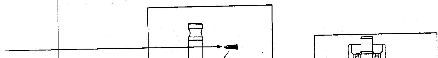
Symbols for Lubrication, Sealants and Adhesives
tion and for application of sealants and adhesives is provided, by using symbols, in the diagram of component parts or on the page following the component parts page, and explarned. Indicates procedures to be performed before the work in that section is started, and procedures to be performed after the work in that section
Maintenance and Servicing Procedures
is finished.
l
l
l Removal steps:
The part designation number corresponds to the number in the illustration to indicate removal steps. Disassembly steps:
The part designation number corresponds to the number in the illustration to indicate disassembly steps. Installation steps:
Specified in case installation is impossible in reverse order of removal steps.
Omitted if installation is possible in reverse order of removal steps.
8 Reassembly steps: Specified in case reassembly is impossible in reverse order of disassembly steps. Omitted if reassembly is possible in
*+ : Indicates that there are essential points for I)+ : Indicates that there are essential points for
Information concerning the locations for lubricareverse order of disassembly steps. necessary. In this example, sealant is applied (where indicated) to the I---
4 . . . . . Grease (multipurpose grease unless there is a brand or type specified) 4 . . . . Sealant or adhesive
a
a
Brake fluid. automatic transmission fluid or air conditioner compressor oil . . . . . Engine oil or gear oil
Adhesive tape or butyl rubber tape

QfitIIICQ TV..&”
CTEEQINC Y.LLI.II.Y CFAR Y_..
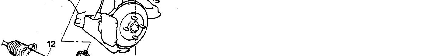
REMOVAL AND INSTALLATION
RnY w-1.
1, Jpn assemble and gear box connecting 2 Connectlo” for return tube 3 Connectm for pressure hose 4 cotter P!” 6 T!e-rod end and knuckle connecting
I J rl”.#l ~“,. dLlrr_. ..__ 10. Center member rear mouniing bou 11, Front exhaust p’pe 4. H 12. Gear box assembly . . 13. Mounting rubber


Y.T-*c Denotes non-rep usable part . As..
- 6


Repair kit or set parts are shown. (Only very frequently used parts
I
I se&an:
iY,W1
3rM&rr&paNo.~3W 1


-
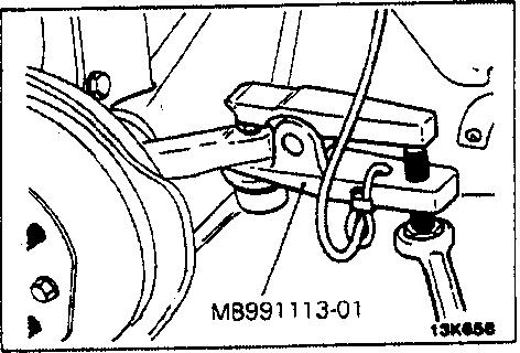
SERVICE POINTS OF REMOVALJ ll37?kM
6. DlSCONNECllON OF TIEROD END
Using the special tool, disconnect the tie rod from the knuckle. ceurion 1. Besretotiethewrdofthespeciaitodtomen
P-. 2. Loosenthenutbutdonotremoveit.
12. REMOVAL OF GEAR BOX ASSEMBLY
37A-24
LUBRlCATlON STEERING - NINA Steering
AND SEALING

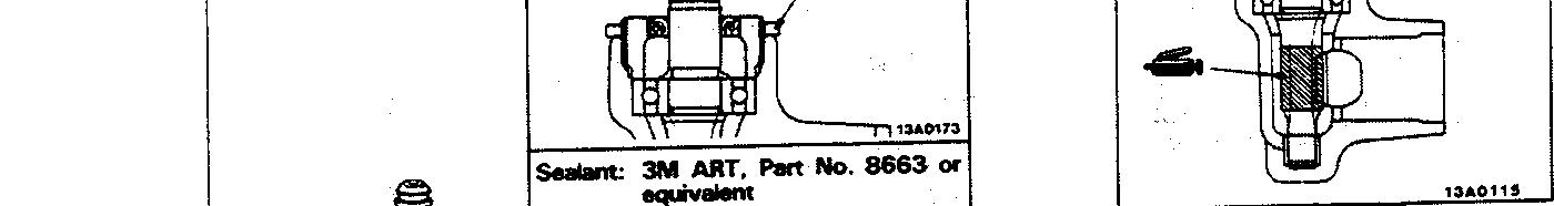
POINTSGear Box
Operating procedures, cautions, etc. on removal, installation, disassembly and reassembly are de[scribed, ,~ 1
Thus number corresponds to the number ?pyi:,“~&‘R~;;?I steps”, “Installation steps” or “Reassemblv steps”.

The title of the page (fOilOWing the page on which the diagram of component parts is presented) indicating the locations of lubncation and sealing procedures.
EXPLANATION OF THE TROUBLESHOOTING GUIDE
Indicates connector’s terminal number. Provides the necessary decurt operation (standing . terminals to be conditions under which the check should be made.
3. Checking the pasmngw compartment-twnpwatu* UnSO!. ~ thermo8tat sensor and refdgwant-tempnaturs sensor ufalits


F, ah
Indicates the circuit diagram
(including the interface of the air conditioning
scription of cirfor basic under-
each sensor t? order to convest lb+ amben
temperawe of the Sensor pm to resistance The sense, power-supply l2.W of The atrcOnd,f,oner control unit s aD&d~to each SmSOt snd lhe voltages of te,mmaIs 116). (151. (17) and (51 are dwded by the reslstme va!ueS.of each ““F reelstance R .. TmuMnhooting hints * Dtagnoss NO 1, The Z’C NO 1’2 The passenger (77-F). ou~sde.ar cPrrlpmme”l-lemperatu4 sensor inpu srgnal IS held -r tnput sigrml is ,, to WC (5IpF). hid to “” . _ N O 13 The air#t,?,mpSf~ SenSO, VlPut SlgMl 6 t+ 10 4% G33-F) : I


-Airwndtlimluconhdunittwmirutwtmge
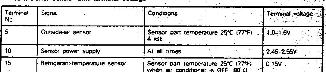
I 16
17 I lYle *“MI Passenger com,wnme”t-tawa.
A~r.,hermos,at sewor 1 sensor ,‘W Parr lem,mat”r~ . 25-c OFFI _: ,.
sensor Pm remoeraure 2% 177% WM” m cQndlt*Ow IS OFF 1 Lo 4 7 L. to WV .L
, o-‘l,W
._. 4 control unit).
I number. Numbers are used in the operation descriptions only as necessary, and these numbers correspond to the numbers used in harness and component layout
Provides hints (including standards for I-- judgement) when troubleshooting procedures are followed. Indicates the onboard diagnostic L: output code No. and the system conditions durina output.
-h
i Indicates the diagrams.
1 Indicates the specification to be used for judgement of the check results. If there is no particular mention of conditions in the ‘Conditions” column, the column shows the specifica- :ion under normal condi- :ions.
EXPLANATION OF CIRCUIT DIAGRAMS
The symbols used in circuit diagrams are used as described below. NOTE
For detailed information concerning the reading of , circuit diagrams, refer to GROUP 54lCircuit Diagrams.
Indicates
a I The broken (-. line indicates the The connector symbol indicates the device side connector (for an intermediate connector, the male side connectorj as seen from the terminal fronl (the connectois rnnnection face). r Indicates that the connector is the direct-inserThe input/output (direr of current flow) relativ the electronic control is indicated by sym (A.V). The (A) symbol indic that current flows in upward direction.

same connector. t

RELAY


devce side con
I

MOTOR
output tion tvoe.


The direction of cu.rreht flow is indicated by the arrow. In this instance, the current flow is in both directions. UP