9 minute read
Oil timing cover retaining bolts and install 2 bolts finger tight. Install dowel pins, chamfer end first. To complete installation, reverse removal procedure

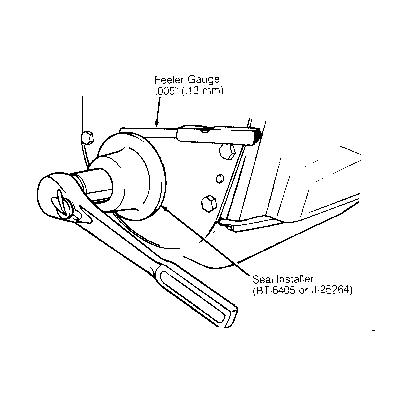
Fig. 6: Timing Gear Alignment Courtesy of GENERAL MOTORS CORP.
TIMING CHAIN & GEARS
Removal & Installation
1. Remove front timing cover. See FRONT TIMING COVER & SEAL. Remove fuel pump eccentric. See
Fig. 4. Align timing marks on camshaft and crankshaft gears. See Fig. 6. 2. Remove camshaft gear and chain as an assembly. Remove crankshaft key BEFORE attempting to remove crankshaft gear. Remove crankshaft gear with a puller (if replacing). To install, reverse removal procedure. With camshaft and crankshaft gear marks aligned, No. 6 cylinder is at TDC on compression stroke. See Fig. 6.
CAMSHAFT
NOTE: Engine must be removed to install camshaft bearings. Ensure oil holes in bearings and block are aligned.
Removal & Installation
1. Remove timing chain and gears. See TIMING CHAIN & GEARS. Discharge A/C system and remove
A/C condenser. Remove distributor cap with plug wires. Remove intake manifold and valve covers. See
INTAKE MANIFOLD and VALVE COVERS. Mark and remove rocker arms, pushrods and lifters. Note location for installation. 2. Remove camshaft retainer plate. Remove flange adapter. See Fig. 4 . Pull camshaft out of engine. If installing new camshaft add EP Lubricant (1051396) to engine oil. To install, reverse removal procedure.
Use EP lubricant on components during installation.
Inspection
Check bearing and lobe surfaces for wear, galling, gouges and discoloration (overheating). Measure lobe lift, bearing journal runout and diameter with camshaft in "V" block. Replace as necessary. See ENGINE SPECIFICATIONS table at end of article.
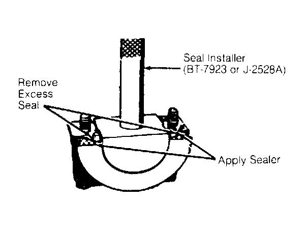
REAR MAIN BEARING OIL SEAL
Removal & Installation
Rear main bearing oil seal is a 2 piece rope seal. The lower portion may be replaced with engine in vehicle. Crankshaft removal is required for replacing upper portion. Use Seal Installer (J-2528A or BT-7923) to install seal. Cut excess seal material flush. Apply Sealer (1050026) to the main bearing cap as shown. See Fig. 7.
Fig. 7: Installing Rear Main Bearing Oil Seal Courtesy of GENERAL MOTORS CORP.
WATER PUMP
Removal & Installation
Disconnect negative battery. Drain cooling system. Remove necessary accessories and brackets. Remove fan and pulley. Disconnect lower radiator hose and heater hoses from water pump. Remove water pump retaining bolts and remove water pump. See Fig. 4. Apply Sealer (10500026) to new gasket and place on water pump. To complete installation, reverse removal procedure.
NOTE: For further information on cooling systems, see ENGINE COOLING.
OIL PAN
1. Disconnect negative battery cable. Remove air cleaner, fan shroud and distributor cap. Raise vehicle and drain crankcase. Disconnect exhaust pipe at manifold, Air Injection Reaction (AIR) pipe clamp and catalytic converter hanger bolts. 2. Remove front starter brace, starter and flexplate access cover. On models with M/T, it may be necessary to remove oil filter for access to flywheel cover bolts. 3. Remove engine mount through bolts and oil pan bolts. Raise engine and lower pan. Position front crankshaft throw and/or counterweights as to clear oil pan. Remove oil pan.
OIL PUMP
Removal & Installation
Remove oil pan. See OIL PAN REMOVAL in this article. Remove oil pump retaining bolts and remove oil pump. To install, reverse removal procedure. See INSPECTION under OIL PUMP at end of this article.
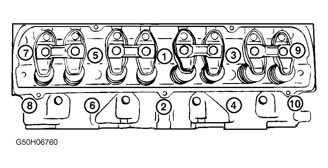
Fig. 8: Exploded View of Cylinder Head Courtesy of GENERAL MOTORS CORP.

CYLINDER HEAD OVERHAUL
NOTE: Keep components together and marked to ensure installation in original position.
VALVE SEAL, SPRINGS & ROTATORS
These may be replaced with cylinder head installed using compressed air method. Intake and exhaust seals are not interchangeable. Intake seals are Gray and exhaust seals are Ivory. See Fig. 8 .
VALVE GUIDES
Check and service guides prior to valve and seat service. Guide replacement information not available from manufacturer. Valve guides may be reamed .003" (.08 mm) oversize and an oversized valve installed.
VALVE SEAT
Valve seat replacement information not available from manufacturer. An oscillating type valve grinder is preferred. If after grinding seat is too wide, use a 20 degree stone to lower seat and 70 degree stone to raise seat. If seats are serviced, valves also must be serviced or replaced.
VALVES
After valve service, measure valve stem and rotator height as shown. See Fig. 9 . There should be .015" (.38 mm) clearance between valve stem and gauge. Clearance between valve rotator and valve stem must be greater than .005" (.13 mm). If not within specifications, replace components as necessar y.
Fig. 9: Checking Valve Stem & Rotator Height Courtesy of GENERAL MOTORS CORP.

HYDRAULIC ROLLER LIFTERS
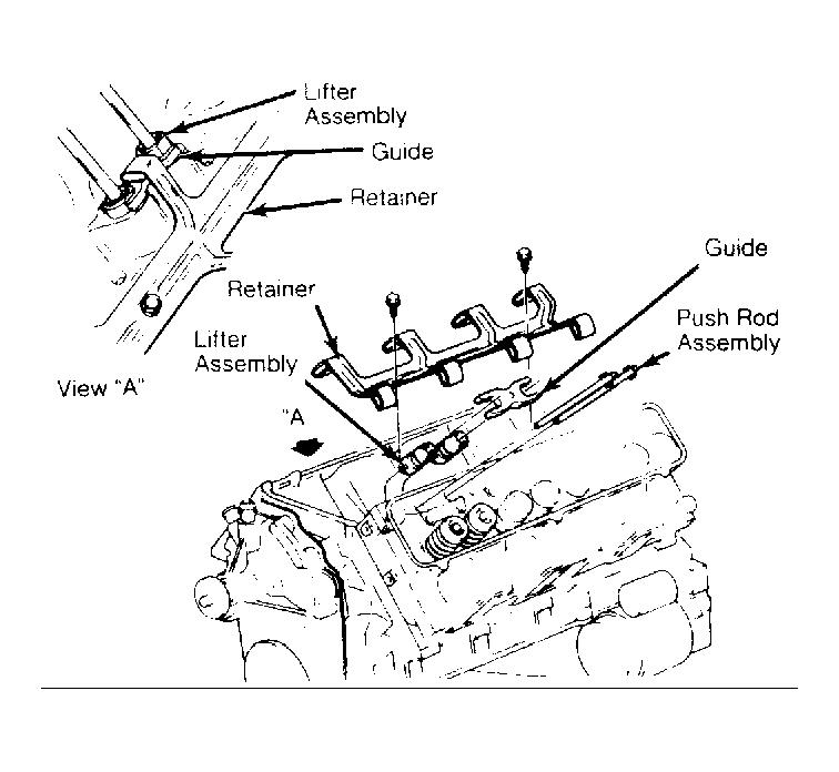
If new lifters are installed, add Conditioner (1052367) to engine oil. Some engines may have both standard and .010" (.25 mm) oversize lifters. Lifters are marked on the side with an "O" if oversized. The outside of lifter bore in cylinder block is also marked with an "O" if oversized. Ensure guide and retainer are installed properly. See Fig. 10.
Fig. 10: Lifter, Guide & Retainer Assembly Courtesy of GENERAL MOTORS CORP.
CAMSHAFT OVERHAUL
Inspection
Check bearing surfaces and lobes for wear, galling, gouges and discoloration (overheating). Measure lift, bearing journal diameter and runout. Replace camshaft if not within specifications. See ENGINE SPECIFICATIONS tables at end of this article. If bearings are replaced, ensure oil holes are properly aligned. If installing new camshaft, add EP Lubricant (1051396) to engine oil.
CYLINDER BLOCK ASSEMBLY OVERHAUL
NOTE: Keep components together and marked to ensure installation in original position.
CYLINDER BLOCK
1. Using a straightedge and feeler gauge, check cylinder block head gasket surface for warpage. If more than .005" (.13 mm) of metal must be removed, replace cylinder block. 2. Check cylinder bore for wear, taper, out-of-round and piston fit. Machine or replace as necessary. See
ENGINE SPECIFICATIONS tables at end of this article.
NOTE: Some oil gallery plugs are drilled to feed oil onto timing chain and distributor. Note position for reinstallation.
PISTON & ROD ASSEMBLY
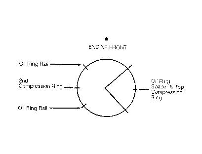
Mark rod and rod cap with matching cylinder number. Match mark piston-to-rod prior to disassembly for reassembly reference. Notch on top of piston faces front of engine. Pin is retained by 2 retainers. No special tools needed for pin removal. Check piston ring end gap and side clearance. Properly install rings on piston. Refer to Fig. Fig. 11 .
Fig. 11: Positioning Piston Ring End Gaps Courtesy of GENERAL MOTORS CORP.
FITTING PISTONS
Production and service pistons have same nominal weight and can be intermixed without affecting engine balance. DO NOT cut oversized pistons down as balance will be affected.
CAUTION: Manufacturer recommends seating bearing caps with leather or brass mallet BEFORE tightening bearing cap bolts. Tighten in proper sequence. See TORQUE SPECIFICATIONS table at end of this article.
CRANKSHAFT & BEARINGS
Bearings are marked with amount of undersize on opposite end of tang or the tang will be marked with a letter. See BEARING IDENTIFICATION table in this article. DO NOT mix standard and undersize bearings. Seat thrust bearing prior to tightening main bearing caps. See CRANKSHAFT THRUST BEARING under CYLINDER BLOCK ASSEMBLY OVERHAUL in this article.
BEARING IDENTIFICATION Letter
A B C
In. (mm)
.0005 (.013) .0010 (.025) .0015 (.038)
CRANKSHAFT THRUST BEARING
Lubricate bearings and crankshaft journals with oil. Lubricate thrust surfaces with GM 1050169. Install main bearing caps. See CAUTION under FITTING PISTONS. Tighten main bearing caps to 11 ft. lbs. (15 N.m). Using a block of wood and hammer, bump crankshaft in each direction to align thrust flanges. See Fig. 12 . Tighten main bearing caps to specification. See TORQUE SPECIFICATIONS table at end of this article.
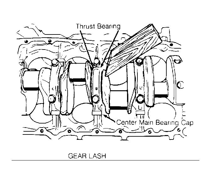
Fig. 12: Seating Crankshaft Thrust Bearing
Courtesy of GENERAL MOTORS CORP.
LUBRICATION
LUBRICATION SYSTEM
A gear-type oil pump provides full pressure lubrication through full flow oil filter. Oil pump is bolted to bottom of cylinder block, inside oil pan. A drive shaft is splined into the distributor and oil pump. Distributor is camshaft driven.
Crankcase Capacity
Crankcase capacity is 4 qts. (4.8L) without oil filter and 5 qts. (4.7L) with oil filter.
Normal Oil Pressure
Oil pressure is minimum 30 psi (2.1 kg/cm 2 ) at 1500 RPM.
OIL PUMP
Inspection
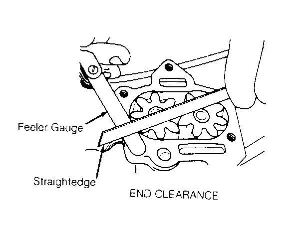
Check oil pump as shown. See Fig. 13-16. Check outside diameter and width of gears. If not within specifications, replace components as necessary. See OIL PUMP SPECIFICATIONS table in this article.
OIL PUMP SPECIFICATIONS Application
End Clearance Gear Lash Gear
Length
Diameter Oil Pump Body
Pocket Depth
Pocket Diameter Side Clearance Regulator Valve-to-Bore Clearance
In. (mm)
.0025-.0065 (.063-.165) .0004-.0065 (.010-.165)
1.5075-1.5095 (38.29-38.34) 1.529-1.531 (38.84-39.89)
1.500-1.509 (38.10-38.33) 1.534-1.539 (38.96-39.09) .0015-.0045 (.038-.114) .0025-.0050 (.063-.13)

Fig. 13: Measuring Oil Pump Gear Lash Courtesy of GENERAL MOTORS CORP.
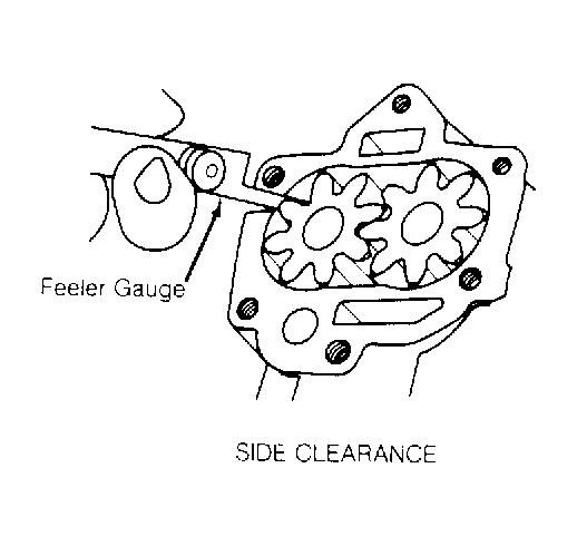
Fig. 14: Measuring Oil Pump Side Clearance Courtesy of GENERAL MOTORS CORP.

Fig. 15: Measuring Oil Pump Pocket Depth & Diameter Courtesy of GENERAL MOTORS CORP.
Fig. 16: Measuring Oil Pump End Clearance Courtesy of GENERAL MOTORS CORP.
TORQUE SPECIFICATIONS
TORQUE SPECIFICATIONS Application
AIR Manifold-to-Cylinder Head Bolt Camshaft Sprocket Bolt Connecting Rod Cap Nut
Step 1
Step 2 Crankshaft Balancer-to-Crankshaft Bolt Cylinder Head Bolt (1)
Step 1
Step 2: Nos. 1-7 & No. 9
Step 3: Nos. 8 & 10 EGR Valve-to-Manifold Bolt Engine Mount-to-Cylinder Block Bolt
Ft. Lbs. (N.m)
20 (27) 65 (88)
18 (24) Additional 70 degrees 200-310 (271-420)
40 (54) Additional 120 degrees Additional 95 degrees 20 (27) 75 (100)
Engine Mount-to-Frame Bolt Exhaust Manifold Bolts Fan-to-Water Pump Bolt Fan Pulley-to-Balancer Bolt Flexplate-to-Converter Bolt Flexplate-to-Crankshaft Bolt Front Timing Cover-to-Block Bolt Fuel Pump Eccentric-to-Camshaft Bolt Intake Manifold Bolts (2)
Step 1
Step 2 Main Bearing Cap Bolt
Nos. 1-4
No. 5 Oil Filter Adapter Bolt Oil Pan
Bolt
Nut Oil Pump-to-Main Cap Bolt Rocker Arm Nut Spark Plug Starter Bolt Transmission-to-Block Bolt Water Pump Bolt
Valve Cover Valve Lifter Guide Retainer (1) Clean and dip entire bolt in engine oil. Tighten in sequence. See Fig. 3. (2) Clean and dip entire bolt in engine oil. Tighten in sequence. See Fig. 1.
ENGINE SPECIFICATIONS
GENERAL ENGINE SPECIFICATIONS
GENERAL SPECIFICATIONS Application
Displacement Bore Stroke Compression Ratio 55 (73) 25 (34) 20 (27) 28 (40) 46 (63) 60 (81) 35 (47) 65 (88)
15 (20) 40 (54)
80 (108) 120 (163) 35 (47)
10 (14) 17 (23) 35 (48) 22 (30) 25 (34) 32 (44) 35 (47) 11 (14)
INCH Lbs. (N.m)
90 (10) 82 (9)
Specification
307 Cu. In. 3.80" (96.5 mm) 3.39" (86.0 mm) 7.99:1
CLICK HERE TO DOWNLOAD THE COMPLETE MANUAL
• Thank you very much for reading the preview of the manual . • You can download the complete manual from: www.heydownloads.com by clicking the link below

• Please note: If there is no response to
CLICKING the link, please download this PDF first and then click on it.
CLICK HERE TO DOWNLOAD THE COMPLETE MANUAL