6 minute read
Northeastern University School of Architecture Architectonic Systems

ARCH 2240: Tuesdays and Fridays 9:50a-11:30a
Office hours: by appointment via Zoom
Advertisement
Project 2: Cavity Wall Section
Assigned: Tuesday, November 1; Due: Friday, November 15 (In -Class Pin-up), December 2 (Final)
Project 2 will investigate the conventions of technical architectural representation by designing and documenting a masonry cavity wall section at 3/4” = 1’‐0” scale. “Working Drawings” or “Construction Documents” are the instrument architects use to precisely describe their constructional intentions to the contractor. Clarity, legibility, and ease of locating information are critical characteristics of any architect’s technical drawing. Ultimately, “Construction Documents” constitute legal documents.
This wall section will be of a two‐story brick‐veneer with a CMU back‐up cavity wall located in the northeast USA. It will have a full basement and a “flat roof” with a “green roof” system. The first floor an d second floor will have different floor structures and different finished surfaces. Your section shall cut through a window at each level. Each window will employ a horizontal solar shading device that is structurally supported from the CMU wall. Not all required construction elements are listed below; however, you will still be responsible for them in your drawing. Do not add borders to your drawings, and use a neutral typeface ( e.g., Arial, Calibri, Helvetica).
Your wall section shall be continuous from foundation footing to the parapet. The exterior shall be to the left, and the interior to the right of your drawing. It will show a lateral depth of 6’ from the exterior face of the wall. All elements shall be clearly and logically labeled: the organization and logic of the labeling must be designed to communicate most clearly your constructional intentions to the contractor. Align vertically and left or right justify your labels.
Similarly, dimension strings must also be designed to communicate most clearly your dimensional intentions to the contractor. You must draw two critical dimension strings that will be continuous lines from the bottom to the top of the drawing: 1. the critical dimensions of the floor construction (basement slab, depth of floor structures, subfloor, finished floor, joists, and beams, and the finished floor- to-finished-ceiling height); 2. the critical dimensions of the CMU wall (top of parapet, top of bond beams, rough openings for windows , bottom of CMU wall).
Line weight is particularly important for legibility of such a complex drawing. Develop a system for dark lines for section cuts, medium lines for internal wall information, and light lines for objects beyond in elevation, dimension lines, and leader lines for notes. Any hatching of materials must be done with discretion and lightness so it does not dominate the drawing. Many important components of masonry cavity wall construction are too thin to represent to scale: often you must exagge rate a material thickness to be able to read it clearly (e.g., for flashing or membranes.) You must make practice PDFs to get the line weights correct.
Requirements For Final Project
Final PDF drawing file called “Last Name ARCH 2240 Project 2 Wall Section” on 24” x 36” vertical format with your name, professor’s name, date, course name and number, scale of drawing (3/4” = 1’‐0” scale), and drawing title (Masonry Cavity Wall Section) in the lower right hand corner.
In addition to the drawing, you must also prepare an outline specification for the footings, foundation walls, CMU and brick cladding and interior finishes by eliminating the items that do not apply to your project from the 3 specification sections provided on Canvas called” Tec Project 2 Brick Cavity Wall Specification .” This will be submitted as a PDF called “Last Name ARCH 2240 Project 2 Specification” as a 8.5” x 11” document.
Projects are due at the beginning of class on the due date. Late projects will be reduced one full letter grade each day it is late. Projects will be evaluated on their completeness and accuracy of detail [90%], quality of craftsmanship and quality of page composition (10%). Please note that digital files are easily shared. You are welcome and encouraged to consult with your classmates, but sharing digital drawing files, even the smallest copying and pasting of lines , is plagiarism.
Elements
1. Foundation/basement [unfinished] minimum 8’-0” floor to ceiling: a. Represent a 1’ deep x 3’ wide continuous poured-in-place concrete footing b. Represent a poured-in-place concrete foundation wall, width according to cavity wall construction c. Represent a 4” basement floor slab with wire mesh, on top of 2” rigid insulation, vapor barrier, and 4” compacted gravel, d. Represent proper drainage mat, waterproofing, footing drain, and crushed gravel e. Represent proper insulation for the basement
2. First floor structure: a. Represent 2x10 floor joists with metal tie straps bearing on the wall that is cut in section b. Represent 3/4” subfloor and 3/4” finished floor
3. First floor walls and ceiling, minimum 8’ -0” finished floor to finished ceiling: a. Represent modular brick veneer, 1” air-space cavity, 2” rigid insulation, and standard CMU back-up wall b. Represent all required flashing and weep holes c. Represent masonry ties every third CMU course d. Represent necessary waterproofing e. Represent exposed CMU walls in the interior f. Represent exposed floor structure above at ceiling
4. Second floor structure: a. Represent 14” deep heavy timber beams bearing on the wall that is cut in section b. Represent 3” solid wood tongue-and-groove (T&G) decking
5. Second floor walls and ceiling, minimum 8’-0” finished floor to finished ceiling: a. Represent modular brick veneer, 1” air-space cavity, 2” rigid insulation, and standard CMU back-up b. Represent all required flashing and weep holes c. Represent masonry ties every third CMU course d. Represent necessary waterproofing e. Represent 5/8” gypsum wall board with proper furring on wall surfaces and strapping for the ceiling
6. Windows minimum 3’-0” tall at each floor (rough openings should be of a dimension relating to CMU construction): a. Represent proper lintels over your window openings b. Represent proper flashing and weep holes at your window openings c. Represent windows as an outline of prefabricated windows: minimal detail required d. Add an exterior horizontal solar shading device detail to each window: this must bypass the brick veneer and attach to the CMU block back up (this may require a separate detail to be made integral to your page composition)
7. Roof structure: see Allen: Fundamentals Chapter 16 Roofing a. Represent 2x10 roof rafters with metal tie straps bearing on the wall that is cut in section b. Represent 3/4” sheathing c. Represent a minimum 2’-0” tall parapet wall measured from the top of your roof membrane d. Represent a single-ply roof membrane and its necessary connection to the parapet wall e. Represent a shallow “extensive” sedum green roof system f. Represent a roof drain in section 3’-0” o.c. from outer face of wall, drain pipe will bend in the space of the roof structure and go away from exterior wall g. Represent a minimum 6” rigid insulation on decking with a 1/4” per 1’-0” slope toward the roof drain h. Represent proper flashing at all critical points at roof and parapet
3 Paper Architecture /origami Golf
This exercise shall be documented with a picture of your paper structure and short descriptions. Please include a paragraph about how you created the origami with the requirements listed below and a second paragraph about what you learned from this exercise.
This exercise will not receive points right now, but it will be part of the course portfolio at the end of the semester. It will count towards your class participation.
In 15 minutes, first with practice sheets, then with a final sheet, fold the paper
1. as few times as possible, such that
2. only three points maximum touch the surface of the table, and
3. he paper structure can support the weight of your pen, while
4. a golf ball can roll under all spans of folded paper between supporting points, but
5. no continuous edges may touch the table, only points are allowable, and
6. no bends are allowed, just creased folds are acceptable, and
7. no tearing of the paper is allowed.
My first attempt was a fail, where it was able to stand on 3 points, and have a golf ball pass through all openings, but could not hold up a pen.
Trial 2
I had tried to approach it by making a triangle and making a shape that would resemble a tetrahedron, but the legs were not able to maintain their position under the weight of the pen.


Trial 1

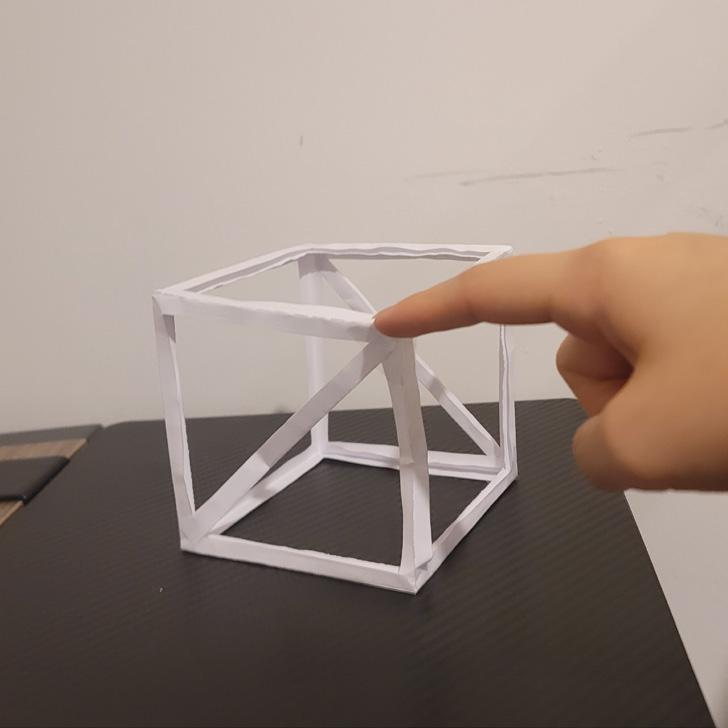
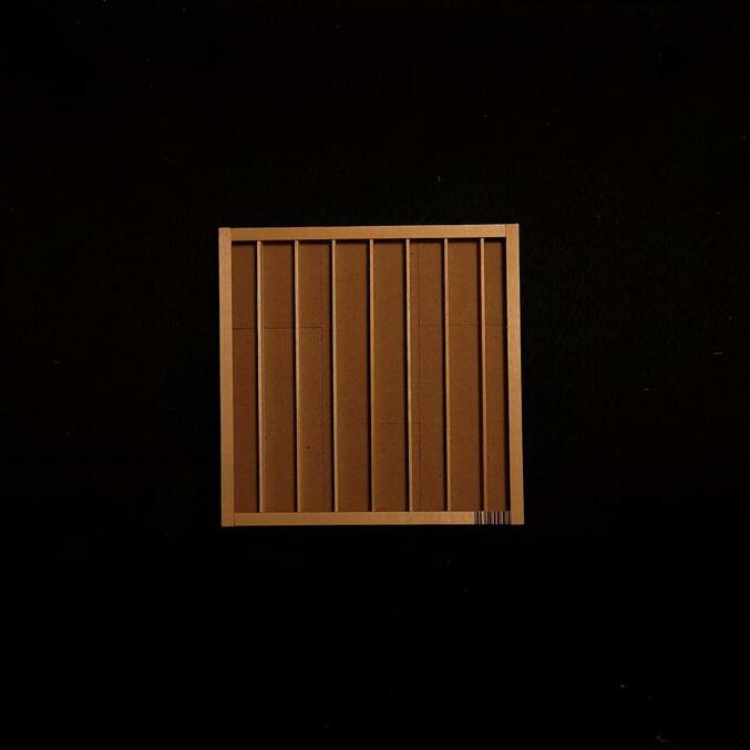
My second attempt was a success, and I folded it to be the form of a rectangular prism, while the legs would make up 3 sides of the prism. While folding it, I made sure to fold all the legs to be the same height. A golf ball was able to pass all three openings, and it was securely able to hold up the weight of a pen.


Conclusion
The biggest change I made was making sure that all legs would stay perpendicular to my surface. I made the roof and legs stay at a right angle, and that was the factor that allowed this structure to be sturdy. Due to the minimal friction I would have at the bottom, I would have to rely on each side holding up the weight, and they should not be a slanted angle, so that the weight of the pen would not naturally push the sides out.