14 PowerTransmission
Motion on Rails Factors to consider when choosing a crossed roller bearing.
I
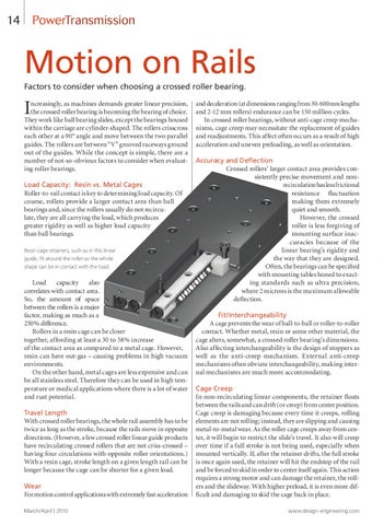
ncreasingly, as machines demands greater linear precision, the crossed roller bearing is becoming the bearing of choice. They work like ball bearing slides, except the bearings housed within the carriage are cylinder-shaped. The rollers crisscross each other at a 90° angle and move between the two parallel guides. The rollers are between “V” grooved raceways ground out of the guides. While the concept is simple, there are a number of not-so-obvious factors to consider when evaluating roller bearings. Load Capacity: Resin vs. Metal Cages Roller-to-rail contact is key to determining load capacity. Of course, rollers provide a larger contact area than ball bearings and, since the rollers usually do not recirculate, they are all carrying the load, which produces greater rigidity as well as higher load capacity than ball bearings. Resin cage retainers, such as in this linear guide, fit around the roller so the whole shape can be in contact with the load.
Load capacity also correlates with contact area. So, the amount of space between the rollers is a major factor, making as much as a 250% difference. Rollers in a resin cage can be closer together, affording at least a 30 to 58% increase of the contact area as compared to a metal cage. However, resin can have out-gas – causing problems in high vacuum environments. On the other hand, metal cages are less expensive and can be all stainless steel. Therefore they can be used in high temperature or medical applications where there is a lot of water and rust potential. Travel Length With crossed roller bearings, the whole rail assembly has to be twice as long as the stroke, because the rails move in opposite directions. (However, a few crossed roller linear guide products have recirculating crossed rollers that are not criss-crossed – having four circulations with opposite roller orientations.) With a resin cage, stroke length on a given length rail can be longer because the cage can be shorter for a given load. Wear For motion control applications with extremely fast acceleration March/April | 2010
and deceleration (at dimensions ranging from 30-600mm lengths and 2-12 mm rollers) endurance can be 150 million cycles. In crossed roller bearings, without anti-cage creep mechanisms, cage creep may necessitate the replacement of guides and readjustments. This affect often occurs as a result of high acceleration and uneven preloading, as well as orientation. Accuracy and Deflection Crossed rollers’ larger contact area provides consistently precise movement and nonrecirculation has less frictional resistance fluctuation making them extremely quiet and smooth. However, the crossed roller is less forgiving of mounting surface inaccuracies because of the linear bearing’s rigidity and the way that they are designed. Often, the bearings can be specified with mounting tables honed to exacting standards such as ultra precision, where 2 microns is the maximum allowable deflection. Fit/Interchangeability A cage prevents the wear of ball-to-ball or roller-to-roller contact. Whether metal, resin or some other material, the cage alters, somewhat, a crossed roller bearing’s dimensions. Also affecting interchangeability is the design of stoppers as well as the anti-creep mechanism. External anti-creep mechanisms often obviate interchangeability, making internal mechanisms are much more accommodating. Cage Creep In non-recirculating linear components, the retainer floats between the rails and can drift (or creep) from center position. Cage creep is damaging because every time it creeps, rolling elements are not rolling; instead, they are slipping and causing metal-to-metal wear. As the roller cage creeps away from center, it will begin to restrict the slide’s travel. It also will creep over time if a full stroke is not being used, especially when mounted vertically. If, after the retainer drifts, the full stroke is once again used, the retainer will hit the endstop of the rail and be forced to skid in order to center itself again. This action requires a strong motor and can damage the retainer, the rollers and the slideway. With higher preload, it is even more difficult and damaging to skid the cage back in place. www.design-engineering.com