A. Baird/A. Palermo/St. Pampanin · Façade damage assessment of concrete buildings in the 2011 Christchurch earthquake
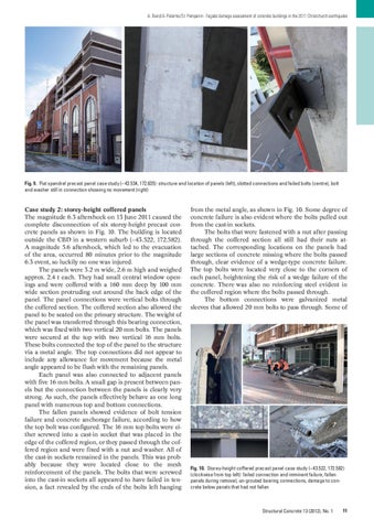
Fig. 9. Flat spandrel precast panel case study (–43.534, 172.635): structure and location of panels (left), slotted connections and failed bolts (centre), bolt and washer still in connection showing no movement (right)
Case study 2: storey-height coffered panels The magnitude 6.3 aftershock on 13 June 2011 caused the complete disconnection of six storey-height precast concrete panels as shown in Fig. 10. The building is located outside the CBD in a western suburb (−43.522, 172.582). A magnitude 5.6 aftershock, which led to the evacuation of the area, occurred 80 minutes prior to the magnitude 6.3 event, so luckily no one was injured. The panels were 3.2 m wide, 2.6 m high and weighed approx. 2.4 t each. They had small central window openings and were coffered with a 160 mm deep by 100 mm wide section protruding out around the back edge of the panel. The panel connections were vertical bolts through the coffered section. The coffered section also allowed the panel to be seated on the primary structure. The weight of the panel was transferred through this bearing connection, which was fixed with two vertical 20 mm bolts. The panels were secured at the top with two vertical 16 mm bolts. These bolts connected the top of the panel to the structure via a metal angle. The top connections did not appear to include any allowance for movement because the metal angle appeared to be flush with the remaining panels. Each panel was also connected to adjacent panels with five 16 mm bolts. A small gap is present between panels but the connection between the panels is clearly very strong. As such, the panels effectively behave as one long panel with numerous top and bottom connections. The fallen panels showed evidence of bolt tension failure and concrete anchorage failure, according to how the top bolt was configured. The 16 mm top bolts were either screwed into a cast-in socket that was placed in the edge of the coffered region, or they passed through the coffered region and were fixed with a nut and washer. All of the cast-in sockets remained in the panels. This was probably because they were located close to the mesh reinforcement of the panels. The bolts that were screwed into the cast-in sockets all appeared to have failed in tension, a fact revealed by the ends of the bolts left hanging
from the metal angle, as shown in Fig. 10. Some degree of concrete failure is also evident where the bolts pulled out from the cast-in sockets. The bolts that were fastened with a nut after passing through the coffered section all still had their nuts attached. The corresponding locations on the panels had large sections of concrete missing where the bolts passed through, clear evidence of a wedge-type concrete failure. The top bolts were located very close to the corners of each panel, heightening the risk of a wedge failure of the concrete. There was also no reinforcing steel evident in the coffered region where the bolts passed through. The bottom connections were galvanized metal sleeves that allowed 20 mm bolts to pass through. Some of
Fig. 10. Storey-height coffered precast panel case study (–43.522, 172.582) (clockwise from top left): failed connection and imminent failure, fallen panels during removal, un-grouted bearing connections, damage to concrete below panels that had not fallen
Structural Concrete 13 (2012), No. 1
11