www.weg.net
Adapting device
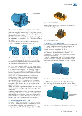
Figure 11 - Six-pin terminal block
Motors in frame size 355A/B are provided with the terminal block indicated in figure 12. Figure 9 - Terminal box mounted on the left side viewing from shaft end
When supplied from the factory with a side mounted terminal box arrangement, this can be positioned on the opposite side simply by rotating the adaptor. Similarly, by removing the adaptor and adjusting the length of the motor leads, the terminal box can be positioned on top of the motor. The flexibility of terminal box positions on the W22 motor offered by the adaptor can be seen in figure 10.
Figure 10 - Terminal box mounted on both sides and on top (versatility)
Conversely, factory supplied motors with the terminal box position on top can be modified to side mounting by fitting the adaptor and extending the motor leads. For the frame size range 63 to 200 the terminal box position is centralized on the motor frame and can be supplied in two configurations - top (standard) or left / right side (optional). A motor with a side mounted terminal box (B3R or B3L) can have the terminal box position located on the opposite side through modification. Please Note: For all terminal box position modifications please contact WEG or your local WEG service centre. For all frames, the terminal box can be rotated in 90째 increments. Motors in IEC frame sizes 315L, 355M/L and 355A/B are supplied as standard with removable cast iron cable gland plates. As an option, the gland plates can be supplied undrilled. Motors are supplied with plastic threaded plugs in the cable glands to maintain the degree of protection during transport and storage. In order to guarantee the degree of protection, cable glands must comply with at least the same degree of protection as that indicated on the motor nameplate. Lack of compliance with such detail can invalidate the motor warranty. If required, please contact the WEG Service Area for further advice. 3.6 Power Supply Connection Leads Motor power supply leads are marked in accordance with IEC 60034-8 and are connected to a terminal block made from a polyester based resin BMC (Bulk Moulding Compound), duly reinforced with fibre glass (see figure 11).
Figure 12 - 355A/B terminal block
3.7 Accessory Connection Leads Accessory terminals are assembled on connectors whenever the motor is supplied with a terminal block. They may be assembled inside the main power terminal box or in a separate accessory terminal box (figure 13). Whether the accessory terminals are assembled inside the main power or a separate terminal box, an M20 x 1.5 threaded hole is provided for fitting of cable glands for the incoming connection leads. In the Terminal Box Drawings section of this catalogue it is possible to check the quantity of connectors that may be assembled inside the main power and accessory terminal boxes.
Figure 13 - Accessory terminal box attached to power terminal box
For all frame sizes, there is also the option of providing a dedicated terminal box for the connection of space heaters, or two separate accessory terminal boxes, as shown in figure 14.
Dedicated space heater box
Figure 14 - Two accessory terminal boxes attached to power terminal box
W22 Electric Motor
11