TAPERED ROLLER BEARING TYPE E HOUSED UNITS ENGINEERING • LOAD AND SPEED RATING TABLES
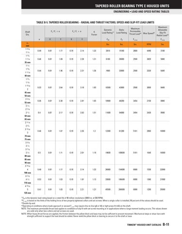
TABLE B-5. TAPERED ROLLER BEARING – RADIAL AND THRUST FACTORS; SPEED AND SLIP-FIT LOAD LIMITS Fa / Fr ≤ e
Shaft Dia. e in. mm 1 3 ⁄ 16 1 1⁄4 1 3⁄8 1 7 ⁄ 16 35 mm 1 1⁄2 1 5⁄8 1 11 ⁄ 16 40 mm 1 3⁄4 1 7⁄8 1 15 ⁄ 16 2 45 mm 50 mm 2 3 ⁄ 16 55 mm 2 1⁄4 2 7 ⁄ 16 2 1⁄2 60 mm 65 mm 2 11 ⁄ 16 2 3⁄4 2 15 ⁄ 16 3 70 mm 75 mm 3 3 ⁄ 16 3 1⁄4 3 7 ⁄ 16 3 1⁄2
X
Fa / Fr > e Y
X
K Factor Y
Maximum Permissible (3) Thrust Load (2) Max Speed
Maximum Allowable Slip-Fit Radial Load (4)
Dynamic Load Rating (1)
Static Load Rating
C90
C0
Fa-max
lbs.
lbs.
lbs.
RPM
lbs.
Fr-max
0.49
0.87
1.77
0.70
2.14
1.23
3810
15760
2000
4490
3100
0.46
0.87
1.89
0.70
2.28
1.31
6100
26000
2590
3820
5000
0.44
0.87
1.96
0.70
2.37
1.36
7860
33000
2590
3320
6400
0.33
0.87
2.64
0.70
3.18
1.83
10300
43000
2590
3050
8400
0.36
0.87
2.38
0.70
2.87
1.65
10900
48200
3454
2730
8900
0.4
0.87
2.17
0.70
2.63
1.51
11600
54000
3454
2420
9500
0.46
0.87
1.87
0.70
2.26
1.3
12300
61200
5181
2060
10000
0.5
0.87
1.71
0.70
2.07
1.19
19600
108600
5181
1640
16000
0.49
0.87
1.77
0.70
2.14
1.23
26900
154000
6908
1530
22000
0.53
0.87
1.63
0.70
1.97
1.13
33000
188400
6908
1360
27000
0.47
0.87
1.83
0.70
2.21
1.27
45500
266000
6908
1200
35000
80 mm 85 mm 90 mm 3 15 ⁄ 16 4 100 mm 4 7 ⁄ 16 4 1⁄2 110 mm 4 15 ⁄ 16 5 125 mm
C90 is the dynamic load rating based on a rated life of 90 million revolutions (3000 hrs. at 500 RPM). Fa-max is based on the limits of the holding force of two properly tightened collars and set screws. When a single collar is installed, 50 percent of the values should be used. (3) Double-lip seal. (4) Operating at conditions where loads approach or exceed Fr-max may require line-to-line (g6 or h6) or light press-fit (m6) on the shaft. NOTE: The maximum permissible thrust load applies to conditions of slip-fit with set screw mounting or in applications where a large moment loading occurs. The values shown are valid only when two collars and set screws are used. NOTE: When heavy thrust forces are applied, the friction between the pillow block and base may not be sufficient to prevent movement. Mechanical stops or shear bars with strength sufficient to support the load should be added. Never weld the pillow block or bearing to secure it to the shaft or base. (1) (2)
TIMKEN® HOUSED UNIT CATALOG
B-11