Thrust Bearings Thrust
Type TSR SPHERICAL ROLLER THRUST BEARINGs D1 H
S
d r T2 T
T1
BA
T3 r
d1 D
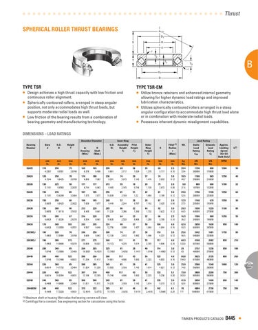
TYPE TSR
• •
Type TSR-EM
• Utilize bronze retainers and enhanced internal geometry
Design achieves a high thrust capacity with low friction and continuous roller alignment. Spherically contoured rollers, arranged in steep angular position, not only accommodates high thrust loads, but supports moderate radial loads as well. Low friction of the bearing results from a combination of bearing geometry and manufacturing technology.
•
• •
allowing for higher dynamic load ratings and improved lubrication characteristics. Utilizes spherically contoured rollers arranged in a steep angular configuration to accommodate high thrust load alone or in combination with moderate radial loads. Possesses inherent dynamic misalignment capabilities.
DIMENSIONS – LOAD RATINGS Shoulder Diameter Inner Ring Load Rating Bearing Bore O.D. Height O.D. Assembly Pilot Outer Fillet (1) Wt. Static Dynamic Approx. D1 Height Height Ring S Radius Load Load Limiting d D T d1 H Number Housing Shaft T1 T2 Height r Rating Rating Speed (Max.) Coa Ct (for Oil (Min.) (Max.) T3 Bath Only)
mm in.
mm in.
mm in.
mm in.
mm in.
mm in.
mm in.
mm in.
mm in.
mm in.
29422
110
230
73
162
165
220
69
26
35
69
29424
120
250
78
174
180
236
74
29
37
74
29326
130
225
58
171
177
215
55
19
29
75
29426
130
270
85
187
195
255
81
31
42
81
29330
150
250
60
194
195
240
57
20
29
87
29430
150
300
90
213
220
285
86
32
44
92
29334
170
280
67
216
220
270
64
23
32
96
29434
170
340
103
243
245
324
99
37
50
104
29338EJ
190
320
78
246
250
308
74
27
38
110
29438EJ
190
380
115
271
275
360
111
41
55
117
29340
200
340
85
264
265
325
81
29
40
114
29440
200
400
122
286
290
380
117
43
59
122
29344
220
360
85
280
285
345
81
29
41
125
29444
220
420
122
307
310
400
117
43
59
133
29348
240
380
85
300
300
365
81
29
41
135
29448EM
240
440
122
315
322
385
87
46
61
142
4.3307 4.7244 5.1181 5.1181 5.9055 5.9055 6.6929 6.6929 7.4803 7.4803 7.8740 7.8740 8.6614 8.6614 9.4488 9.4488
9.0551 9.8425 8.8583
10.6299 9.8425
11.8110 11.0236 13.3858 12.5984 14.9606 13.3858 15.7480 14.1732 16.5354 14.9606 17.3228
2.8740 3.0709 2.2835 3.3464 2.3622 3.5433 2.6378 4.0551 3.0709 4.5276 3.3465 4.8031 3.3464 4.8031 3.3464 4.8031
6.378 6.850 6.744 7.375 7.638 8.405 8.504 9.567 9.685
10.669 10.3937 11.254 11.024 12.106 11.811 12.4016
6.496 7.087 6.963 7.677 7.677 8.661 8.661 9.646 9.843
10.827 10.4331 11.417 11.220 12.205 11.811 12.6772
8.661 9.291 8.465
10.039 9.449
11.220 10.630 12.756 12.126 14.173 12.7953 14.961 13.583 15.748 14.370 15.1575
2.717 2.913 2.165 3.189 2.244 3.386 2.520 3.898 2.913 4.370 3.4252 4.606 3.189 4.606 3.189 3.4252
1.024 1.142 0.748 1.22 0.787 1.260 0.906 1.457 1.063 1.614 1.1417 1.693 1.142 1.693 1.142 1.8110
1.378 1.476 1.130 1.669 1.142 1.732 1.280 1.968 1.496 2.185 1.5748 2.323 1.614 2.323 1.614 2.4016
2.717 2.933 2.972 3.189 3.425 3.622 3.780 4.094 4.331 4.606 4.4882 4.803 4.921 5.236 5.315 5.5906
mm in.
kg. lbs.
2.5
33.4
3.0
18.5
0.10 0.12
2.0
33.4 40.7
9.8
0.08
21.6
3.0
23.9
2.0
12.5
3.0
29.3
2.5
16.5
4.0
42.4
3.0
25.6
0.12 0.08 0.12 0.10 0.16 0.12
4.0
52.6 27.5 64.5 36.3 93.5 56.5
60.3
0.16
133.0
3.0
29
0.12
4.0
63
69.8
0.16
154.0
3.0
33.9
0.12
5.1
74.8
73.9
0.20
163.0
3.0
41.9
0.12
6.1
0.24
92.4
78
171
kN lbs. 1150
260000
1180
256000
880
197000
1730
388000
1140
255000
1930
440000
1500
340000
2650
600000
2442
549000
4168
937000
2157
485000
3625
815000
2500
550000
3800
865000
2650
600000
4884
1098000
k(2)
kN RPM lbs. 800
1500
30
965
1350
40
600
1700
22
1120
1250
60
670
1550
30
1220
1100
80
880
1350
50
1630
950
140
1481
1150
80
2482
850
210
1236
950
100
2135
800
260
1340
1000
120
2200
750
300
1400
950
140
2736
750
350
176000 216000 132000 253000 150000 275000 196000
365000 333000 558000 278000 480000 300000 500000 315000 615000
(1) Maximum shaft or housing fillet radius that bearing corners will clear.
TIMKEN PRODUCTS CATALOG
B445
•
(2) Centrifugal force constant. See engineering section for calculations using this factor.
A