Telescopic pillars
TELEMAG
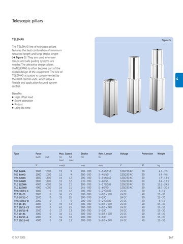
Figure 5
The TELEMAG line of telescopic pillars features the best combination of minimum retracted length and large stroke length (➔ figure 5). They are used wherever robust and safe guiding systems are needed.The attractive design allows theTELEMAG to often become part of the overall design of the equipment. The line of TELEMAG actuators is complemented by the KOM control units, which allow a flexible and application focused system control.
4
Benefits: ● High offset load ● Silent operation ● Robust ● Long life time
Type
Force push
pull
N TGC 8AWA TGC 8AWD THC 8AWA THC 8AWD TLC 12ZWA TLC 12ZWD THG 10/11-C TLT 10-C1 TLG 10/11-C THG 10/11-B TLT 10-B1 TLT 10/11-C2 TLG 10/11-B TLT 10-A1 TLG 10/11-A TLT 10/11-A2
© SKF 2005
1000 1000 1800 1800 4000 4000 1000 1000 1500 2000 2000 2000 2500 3000 4000 4000
1000 1000 1800 1800 4000 4000 0 0 0 0 0 0 0 0 0 0
Max. Speed no full load load
Stroke (S)
Retr. Length (L)
Voltage
Protection
Weight
mm/s
mm
mm
V
IP
kg
200 - 700 300 - 700 200 - 700 230 - 700 100 - 700 255 - 700 200 - 700 300 - 700 200 - 700 200 - 700 300 - 700 300 - 700 200 - 700 300 - 700 200 - 700 300 - 700
S + 145/150 S + 45/50 S + 155/160 S + 60/65 S + 175/185 S + 60/70 S + 270/180 S × 0.5 + 170 S + 180 S + 270/180 S × 0.5 + 170 S × 0.5 + 240 S + 180 S × 0.5 + 170 S + 180 S × 0.5 + 240
120/230 AC 120/230 AC 120/230 AC 120/230 AC 120/230 AC 120/230 AC 24 DC 24 DC 24 DC 24 DC 24 DC 24 DC 24 DC 24 DC 24 DC 24 DC
30 30 30 30 30 30 30 40 30 30 40 40 30 40 30 40
4.5 - 7.5 5.9 - 9.5 7.9 - 13.5 8.6 - 17.5 15.2 - 24.5 18.3 - 30.5 8 - 14 15 - 30 15 - 30 8 - 14 15 - 30 15 - 30 15 - 30 15 - 30 15 - 30 15 - 30
11 11 15 15 16 16 15 36 33 7 19 42 17 16 14 19
9 9 12 12 11 11 12 25 25 5 13 25 13 11 10 13
167