7
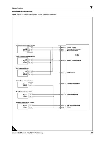
2800 Series Analog sensor schematic Note: Refer to the wiring diagram for full connection details.
Atmospheric Pressure Sensor +5V Signal Return
A C B
J2/2 J2/14 J2/3
+5VDC Supply Atmospheric Pressure Analogue Return
ECM
Turbo Outlet Pressure Sensor +5V Signal Return
A C B
J2/40
Turbo Outlet Pressure
A C B
J2/24
Oil Pressure
J2/32
Coolant Temperature
J2/33
Fuel Temperature
J2/35 J2/18
Inlet Air Temperature Return
Oil Pressure Sensor +5V Signal Return
Water Temperature Sensor Signal Return
C B
Fuel Temperature Sensor Signal Return
C B
Inlet Air Temperature Sensor Signal Return
C B
A Diagnostic Manual, TSL4247, Preliminary
89
