Fuel System - Operation and Tests
General Operation (MICO in-Line Fuel Injection Pump)
PY2222
–UN–13MAR04
120 17
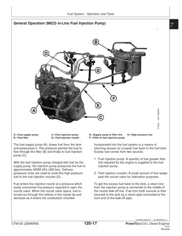
A—Fuel supply pump B—Fuel filter
C—Fuel injection pump D—Fuel injection nozzle
E—Supply pump to filter line F—Filter to fuel injection pump
Incorporated into the fuel system is a means of returning excess (or unused) fuel back to the fuel tank. Excess fuel comes from two sources:
The fuel supply pump (A), draws fuel from the tank and pressurizes it. This pressure permits the fuel to flow through the filter (B) and finally to fuel injection pump (C). With the fuel injection pump charged with fuel by the supply pump, the injection pump pressurize the fuel to approximately 45000 kPa (450 bar). Delivery (pressure) lines are used to route this high pressure fuel to the fuel injection nozzles (D). Fuel enters the injection nozzle at a pressure which easily overcomes the pressure required to open the nozzle valve. When the nozzle valve opens, fuel is forced out through the orifices in the nozzle tip and atomizes as it enters the combustion chamber.
G—High pressure line
1. Fuel injection pump: A quantity of fuel greater than that required by the engine is supplied to the fuel injection pump. 2. Fuel injection nozzles: A small amount of fuel seeps past the nozzle valve for lubrication purposes. To get the excess fuel back to the tank, a return line from the injection pump is connected to the middle of the nozzle leak-off line. Fuel from both sources is then returned to the tank by a return pipe connected to the front end of the leak-off pipe.
CD03523,0000142 –19–20SEP04–1/1
CTM125 (22MAR06)
120-17
POWERTECH 2.9 L Diesel Engines 032306
PN=259