Camshaft and Timing Gear Train
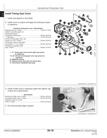
Install Timing Gear Cover 1. Install new gasket on front plate. 2. Install cover on engine and apply the following torques in sequence. (11 lb-ft)
(22 lb-ft) (52 lb-ft) (35 lb-ft) (35 lb-ft) (70 lb-ft)
CD30609
1...17—Timing gear cover-to-front plate cap screws (in sequence) 18...23—Oil pan-to-timing gear cover cap screws (in sequence) A—Magnetic pick-up B—Injection pump drive gear nut access plug C—Oil pressure regulating valve plug
–UN–16JUN98
Aluminum timing gear cover—Specification Magnetic pick-up—Torque .............................................. 15 N•m Injection pump drive gear nut access plug torque— Composite material plug.................................................. 30 N•m — Steel plug .................................................................... 70 N•m Oil pan to timing gear cover, cap screws (18—23)—Torque ............................................... 50 N•m Timing gear cover to front plate, cap screws (1—17)—Torque .......................................... 50 N•m Oil pressure regulating valve plug—Torque ................................................................... 95 N•m
CD,CTM125,128 –19–30JUL04–1/2
Specification Aluminium oil filler neck—Torque ................................... 50 N•m (35 lb-ft) Composite oil filler neck—Torque ................................... 30 N•m (22 lb-ft) Obturation plate for oil filler orifice—Torque ................................................................ 50 N•m (35 lb-ft)
4. Cut off protruding edge of gasket.
–UN–04MAY98
3. Install oil filler neck or obturation plate then tighten cap screws (A) to specification.
CD30610
20 18
CD,CTM125,128 –19–30JUL04–2/2
CTM125 (22MAR06)
20-18
POWERTECH 2.9 L Diesel Engines 032306
PN=138