Camshaft and Timing Gear Train
Remove Front Plate 1. Proceed as follows in case of front plate replacement:
CD30186
–UN–07MAR95
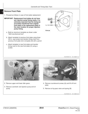
IMPORTANT: Replacement front plates do not have any injection pump timing marks. It is extremely important that the timing be accurately transferred from original front plate to the replacement plate in the exact location for proper injection pump timing. a. Build an aluminum template as shown under “Self-manufactured tool”. b. Attach template to previous front plate using three 3/8 in. cap screws and transfer timing mark from previous front plate (A) to template (B) with a pencil. c. Attach template to new front plate and transfer timing mark to the new front plate (C) using a scriber.
2. Remove upper and lower idler gears. 3. Remove camshaft, fuel injection pump and oil pump.
–UN–04MAY98 CD30598
–UN–19MAY98
CD,CTM125,118 –19–17JAN01–1/2
CD30597
20 8
4. Remove countersunk screws (A) and lift off front plate. 5. Remove oil by-pass valve and spring (B).
CD,CTM125,118 –19–17JAN01–2/2
CTM125 (22MAR06)
20-8
POWERTECH 2.9 L Diesel Engines 032306
PN=128