Polymer Products
Î Our products are used by customers in over 40 countries to protect the electrical supply to vital operations and ensure systems keep running safely and securely in the event of a short circuit.
Î Our products are specified and installed across a broad spectrum of industries and installation types, from nuclear power plants to oil rigs; city centre substations to major rail, road and air transport infrastructure projects.

Î Our in-house engineering capabilities allow for constant product development and innovation, and the creation of bespoke solutions for individual project specifications.
Î Our manufacturing headquarters in North Yorkshire, England are ISO9001, 14001 and 45001 certified and all our cable cleats are manufactured to IEC 61914:2015 and short circuit tested as standard prior to being brought to market. We also offer project specific short circuit testing.

Î Our brand is built upon a culture of trust and integrity, and our reputation reflects this.
Î We are an equal opportunities employer, and are committed to lessening our environmental impact and carbon footprint in every aspect of our business.
HOLDING POWER – TRIED, TESTED, TRUSTED AND RELIED UPON
02
We are widely recognised as the global leader in the design and manufacture of safety critical electrical cable cleats and fixing solutions.
Trident® 12 Trident® with spacer 14 Solus Clamp 16 No Bolts Cleat™ 18 2F+ 20 Triple Cable Surround 22 1F 24 Fixings are not supplied as standard but are available on request. 03
QUICK SELECTION GUIDE
Trident® page 12 Solus Clamp page 16 Trident® with spacer page 14 No Bolts Cleat™ page 18 Triplex Cable Surround™ page 22 2F+ page 20 1F page 24
04
MATERIAL OPTIONS
ELLIS CODE GFN: GLASS FILLED LSF NYLON
Î High grade glass filled black nylon polymer. Heat stabilised – suitable for 120oC installations. Low smoke and fume (LSF), UL94 V-0 classified, zero halogen and phosphorus free. Very good mechanical and electrical properties. Excellent UV performance.
ELLIS CODE LSF: LSF NYLON
Î High grade unreinforced nylon polymer. Low smoke and fume (LSF), UL94 V-0 classified, zero halogen and phosphorus free. Good mechanical and electrical properties. Very good UV performance.
ELLIS CODE LUL: LONDON UNDERGROUND APPROVED MATERIAL
Î Specially formulated polymer to comply with the stringent material performance requirements of the London Underground 1-085 standard, in relation to limited oxygen index, smoke density and toxicity.
ELLIS CODE B: BLACK POLYPROPYLENE
Î Standard black Polypropylene. The material is extremely tough and durable. It has excellent impact resistance, is resistant to water and chemicals and has good UV performance.
Ellis offers products in a range of materials to suit the requirements of the specific application.
05
WORLDWIDE DISTRIBUTORS
Ellis is represented by a network of International distributors, providing our customers with local and knowledgeable support.
06
07
TECHNICAL ADVANTAGES
All our products are designed in house. Our Design team use the latest CAD and FEA software to develop and refine designs to meet and exceed industry requirements. Following manufacture of the products our design team build the short circuit testing rigs. This important step allows them to see first-hand how easy the products are to install and implement any design changes required to further improve the product.
CUSTOMER SPECIFIC DESIGNS
Here at Ellis Patents we understand that different markets and varying situations demand different product solutions. As problem solving engineers and a leading manufacturer of cable cleats we thrive on new challenges. When our standard product range isn’t quite what you need, we can design, develop test and manufacture project specific, bespoke products to suit your specific requirements. We call this the Ellis Innovation Hub.
REFINED DESIGN AND EASE OF USE SAFETY IS OUR PRIORITY
All of our cleats are tested in line with the international standard IEC 61914. Each product goes through six individual tests including short circuit testing in order to meet the requirements of this standard.
08
LONG TERM UV TESTING
In addition to the tests carried out to meet IEC 61914 we also carry out long term UV testing. This allows us to confidently recommend products that will be suitable for outdoor applications. Ellis products are designed with an allowance for this degradation over time to ensure they are still within acceptable safety limits even at the end of their design life.
USE OF LINERS
A number of Ellis products are available with the option of liners. Liners are project and product specific and can be useful in the following situations:
Î VIBRATION DAMPING.
Î PROVIDES A COMPLIANT SURFACE FOR CABLES THAT HAVE A SENSITIVE OUTER SHEATH.

Î THE LINERS HELP ABSORB ANY DIMENSIONAL CHANGES CAUSED BY CHANGES IN TEMPERATURE OR OPERATIONAL LOAD.

FIXING SOLUTIONS
Ellis supply a variety of fixings and our team are happy to help you select the correct type for your chosen product and installation. We also have a fixing calculator tool on our website to assist with this.


09
MECHANICAL STRENGTH VS DYNAMIC STRENGTH
The international standard IEC 61914 includes a formula in Annex B that enables a designer to calculate the force between two conductors during a fault. If the strength of a particular cable cleat is known, the optimum spacing of the cable cleat along the cable can be calculated in order to restrain the force created by the fault.
The strength of a cable cleat is often determined using a mechanical tensile test (tensile to failure), the results may be misleading because the force is applied in a slow and controlled manner which does not replicate fault conditions. In a short circuit fault the forces are applied almost instantaneously and oscillate in every direction. Experience shows that a cable cleat that survives a mechanical tensile test at a given force will not necessarily survive a short circuit test, even if forces are the same.
Consider the properties of glass; immensely strong under tension but subject to brittle failure when impacted.
CALCULATION OF CLEAT SPACING AND SELECTION OF CLEAT TYPE
Where the system peak fault current and the cable diameter are known the following formula, taken from the International standard (IEC 61914), can be used to calculate the forces between two conductors in the event of a three phase fault.
Where:
Ft = force in Newton/metre (N/m)
ip = peak short-circuit current in kiloamp (kA)
S = distance between the centrelines of
the conductors in metres (m)
The preferred method of selection is based on a short circuit test. Ft = 0.17 x ip 2 S
Once Ft in N/m has been determined then the force for each potential cleat can be calculated. Metric ladder typically has rungs at 300mm intervals, so cleat spacing is usually a multiple of this distance. So, Ft x 0.3 gives the force a cleat will see if spaced at 300mm, Ft x 0.6 for 600mm etc.
Ft x cleat spacing can then be compared to the cable cleat resistance to electromechanical force and then the cleat type and spacing can be selected.
Please refer to the Ellis Patents Black Book for more examples and information on the calculation of cable cleat spacing. Alternatively Ellis also provide an online cleat calculator to simplify selection: www.ellispatents.co.uk/cleat-calculator/
10
CABLE CLEAT RESISTANCE TO ELECTROMECHANICAL FORCE
ALWAYS REMEMBER
Whole job cost should always be considered as costs can often be reduced by using a stronger, more expensive cable cleat at a wider spacing than a cheaper option at more regular intervals.
CLEAT SELECTION QUESTIONS
CABLE DIAMETER
Cable diameter is critical to selecting the appropriate product. Cables have a tolerance that affects the diameter. This should be considered to ensure the cleat selected will still fit the cable even if the cable arrives on site at the limits of its size range.
MAX PEAK SHORT CIRCUIT CURRENT
Knowing the maximum peak short circuit current as specified by the system designer allows the appropriate cleat and spacing to be selected. The calculation formula uses peak current, however this is often unavailable with a Root Mean Square (RMS) value given instead.
To calculate the peak current from the RMS, IEC 61439-1 Low voltage switchgear and control gear assemblies is commonly referred to, which uses the following multiples:
CABLE ARRANGEMENT
Cables are generally laid side by side or in trefoil formation. For accurate SC levels to be calculated the layout is required. Knowing the formation allows the correct style of cleat to be selected. Triplex is a variant of trefoil cable formation where the cables are twisted together. This can present a challenge for cleating. To remedy this Ellis offer a triplex cable surround.
RMS value of SC Multiple current (kA) 10 < I ≤ 20 2 20 < I ≤ 50 2.1 50 < I 2.2 CLEAT SPACING CLEAT TYPE 300mm 600, 900, 1200mm Strength (N) SC Level (kA) Strength (N) SC Level (kA) Alpha 9,500 82 15,000 73 Vulcan+, Protect and SD Flexi-strap 25,000 13436,000115 Emperor, Colossus and HD Flexi-strap 51,000 19563,000149 Trident 24,500 13225,00094 Trident with insert 11,400 106-Solus GFN 11,000 164--
11
The values in the above table are derived from actual short circuit tests carried out by Ellis. Test report numbers are detailed on individual product data sheets and are available upon request. At 300mm spacing significantly more force is transmitted to the cleat by the cable compared to 600mm spacing and above.
Î MANUFACTURED AS STANDARD IN A HIGH STRENGTH
LSF GLASS FILLED NYLON

Î SINGLE OR TWO BOLT CLEAT FIXING OPTIONS
Î SHAPING OF THE CLEAT ENSURES CABLES ARE HELD IN A TREFOIL FORMATION ACROSS THE RANGE


Î SHORT CIRCUIT AND MECHANICALLY TESTED TO IEC 61914
TR24-292429122917792.5M10360
TR27-322732126957798.5M10370
TR30-36303613410477104.5M10383
TR34-41344114411277114.5M10485
TR39-47394715612477125M12568
TR45-54455417213877145M12666
TR52-62526219015377160M12793
TR60-72607221517798182M121100
TR69-83698323819898205M121300
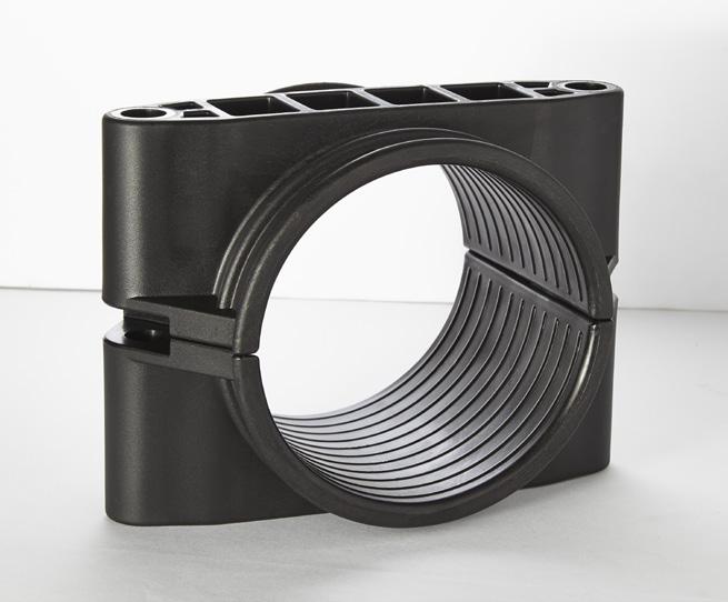
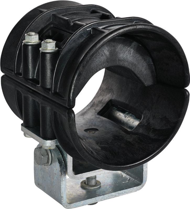
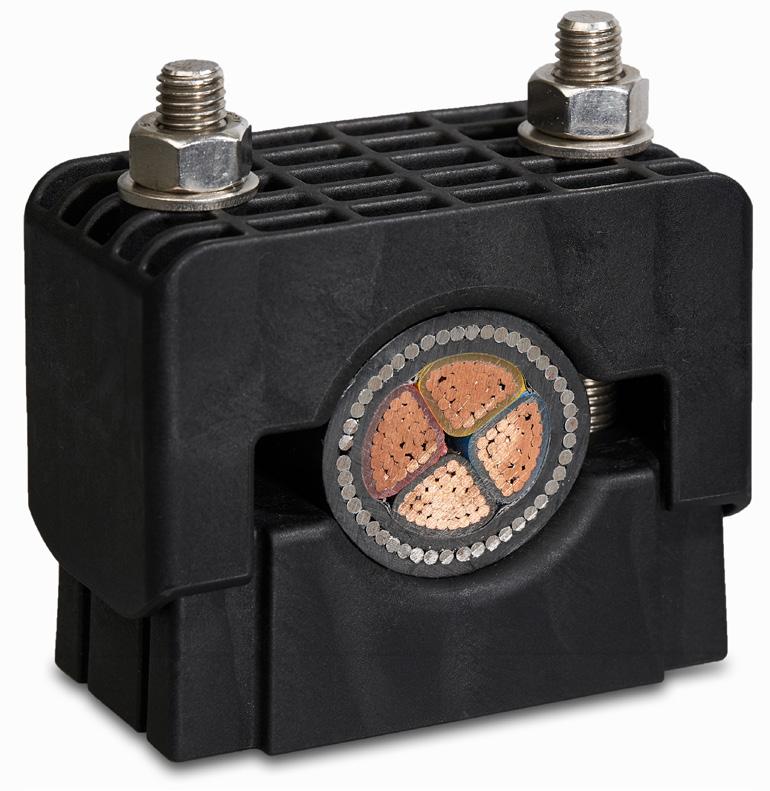
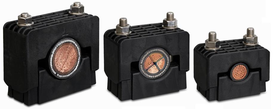
SHAPING OF THE TRIDENT CLAMPS ENSURES CABLES ARE MAINTAINED IN A TRUE TREFOIL FORMATION ACROSS ITS RANGE-TAKE, UNLIKE SIMILAR POLYMERIC CLAMPS ON THE MARKET.
TRIDENT ®
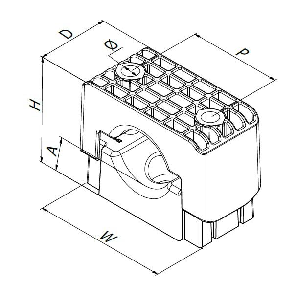
PART NO. CABLE RANGEDIMENSIONS (mm) WEIGHT (g) MIN Ø (mm) MAX Ø (mm) WHDPF
Polymeric Trefoil Cleat
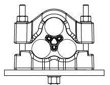
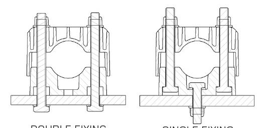
FIXING OPTION 1: 2
M10/M12 FIXINGS
12
x
FIXING OPTION 2: 1 X M12 FIXING
TESTING SUMMARY
Trident Cleats have been tested in line with the International Standard ‘Cable Cleats for Electrical Installations’ IEC 61914:2015. Typical results are detailed below, please note that these testing values are maximums and safety factors appropriate to your application should be used.
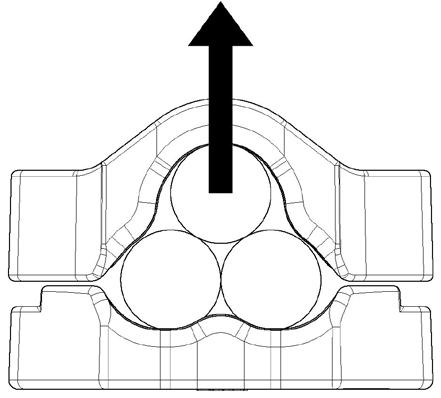
LATERAL LOAD ‘VERTICAL’ DIRECTION
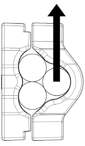
LATERAL LOAD ‘HORIZONTAL’ DIRECTION
PROPERTY CLASSIFICATION CLAUSE IEC 61914 UNITS / CLASSIFICATION TEST DATA CLEAT TYPE 6.1.2 NON-METALLICTEMP. FOR PERMANENT APPLICATION 6.2 °C -40 to +120 UV RESISTANCE 6.5.1.2 XENON ARC METHOD A PASS CORROSION RESISTANCE 6.5.2 N/A N/A IMPACT RATING 6.3.5 VERY HEAVY PASS FLAME PROPAGATION TEST 10.0, 10.1 APPLICATION TIME ≥30s PASS AXIAL LOAD RATING 6.4.3, 9.4 NEWTONS (N) 1100 LATERAL LOAD RATING 6.4.2, 9.3 NEWTONS (N) HORIZONTAL - 2250N VERTICAL -2250N RESISTANCE TO ELECTROMECHANICAL FORCE (SHORT CIRCUIT TESTING) 6.4, 6.4.5, 9.5 CLEATS AT 300MM INTERVALS (WITHSTANDING MORE THAN ONE SHORT CIRCUIT) 134kA (REPORT No. PDL-18.071.6) CABLE OD= Ø36mm RESISTANCE TO ELECTROMECHANICAL FORCE (SHORT CIRCUIT TESTING) 6.4, 6.4.5, 9.5 CLEATS AT 600MM INTERVALS (WITHSTANDING MORE THAN ONE SHORT CIRCUIT) 94kA (REPORT No. PDL-18.071.5) CABLE OD= Ø36mm
This information is subject to change without notice. The information provided has been generated in laboratory conditions and as such results in use may vary. 13
TRIDENT WITH SPACER
Î MANUFACTURED AS STANDARD IN A HIGH STRENGTH LSF GLASS FILLED NYLON
Î SINGLE OR TWO BOLT CLEAT FIXING OPTIONS
Î SHAPING OF THE CLEAT ENSURES CABLES ARE HELD IN A TREFOIL FORMATION ACROSS THE RANGE
Î SHORT CIRCUIT AND MECHANICALLY TESTED TO IEC 61914

Î SPACER PIECE ENSURES EQUIDISTANT CABLE SPACING WHILST PROVIDING A LARGE CLAMP RANGE-TAKE WHEN USED WITH THE STANDARD TRIDENT CLAMP
Î FIXINGS ARE NOT SUPPLIED AS STANDARD BUT ARE AVAILABLE ON REQUEST
TR29-41SP293414411577114.5M10530
TR33-47SP333915612777125M12618
TR41-54SP414517214177145M12706 TR45-54
NOTE: REMOVAL OF THE SPACER PIECE CAN BE UTILISED TO PROVIDE A PRODUCT WITH A LARGE RANGE-TAKE. REFER TO THE STANDARD TRIDENT DATA SHEET.

PART NO. CABLE RANGEDIMENSIONS (mm) WEIGHT (g) CORRESPONDING TRIDENT MIN Ø (mm) MAX Ø (mm) WHDPF
TR34-41
TR39-47
14
Polymeric Trefoil Cleat
Trident cleats have been tested in line with the international standard ‘Cable Cleats for Electrical Installations’ IEC 61914:2015. Typical results are detailed below, please note that these testing values are maximums and safety factors appropriate to your application should be used.
CLEATS AT 300MM INTERVALS (WITHSTANDING MORE THAN ONE SHORT CIRCUIT)

106kA (REPORT No. PDL21.085.03)
CABLE OD= Ø36mm CABLE SPACING = 50mm
1)SP VARIANTS HAVE A DIFFERENT LOAD WITHSTAND TO STANDARD VARIANTS, PEASE CONTACT ELLIS FOR FURTHER INFORMATION.

2)‘FIXING OPTION 1’ S/C STRENGTH IS DERATED. REFER TO ELLIS FOR ‘FIXING OPTION 1’ SHORT CIRCUIT WITHSTANDS. PLEASE CONTACT ELLIS.
3)THE OPERATING TEMPERATURE IS BASED ON THE TEST REQUIREMENTS OF IEC 61914:2015 ONLY.
TRIDENT
OTHER PRODUCTS
SHAPING OF THE TRIDENT CLAMPS ENSURES CABLES ARE MAINTAINED IN A TRUE TREFOIL FORMATION ACROSS ITS RANGE-TAKE, UNLIKE SIMILAR POLYMERIC CLAMPS ON THE MARKET. UNEQUAL TREFOIL FORMATIONS CAN CAUSE ADDITIONAL VOLTAGE DROP.
‘SP’ VARIANTS UTILISE A DISTANCE WEDGE TO INCREASE RANGE-TAKE. EQUAL SPACING BETWEEN THE CABLES IS MAINTAINED.
FIXING OPTION 1: 2 x M10/M12 FIXINGS FIXING OPTION 2: 1 X M12 FIXING
PROPERTY CLASSIFICATION CLAUSE IEC 61914 UNITS / CLASSIFICATION TEST DATA CLEAT TYPE 6.1.2 NON-METALLICTEMP. FOR PERMANENT APPLICATION 6.2 °C -60 to + 60 UV RESISTANCE 6.5.1.2 XENON ARC METHOD A PASS CORROSION RESISTANCE 6.5.2 N/A N/A IMPACT RATING 6.3.5 VERY HEAVY PASS FLAME PROPAGATION TEST 10.0, 10.1 APPLICATION TIME ≥30s PASS AXIAL LOAD RATING 6.4.3, 9.4 NEWTONS (N) REFER TO ELLIS LATERAL LOAD RATING 6.4.2, 9.3 NEWTONS (N) REFER TO ELLIS RESISTANCE TO ELECTROMECHANICAL FORCE (SHORT CIRCUIT TESTING) 6.4, 6.4.5, 9.5
This information is subject to change without notice. The information provided has been generated in laboratory conditions and as such results in use may vary. 15
TESTING SUMMARY
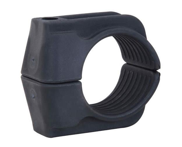
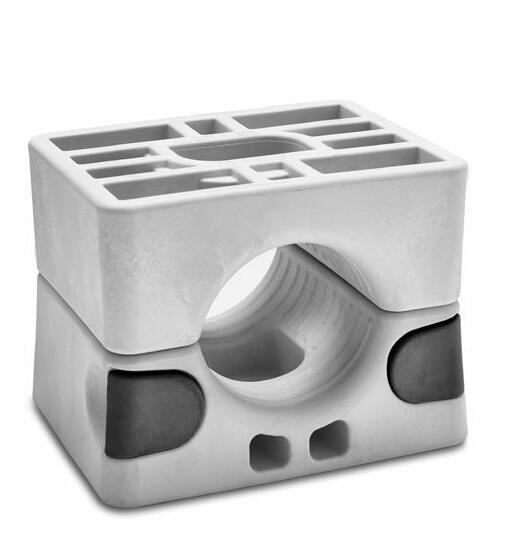
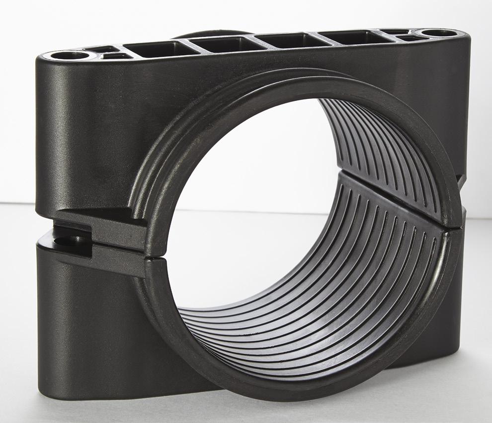
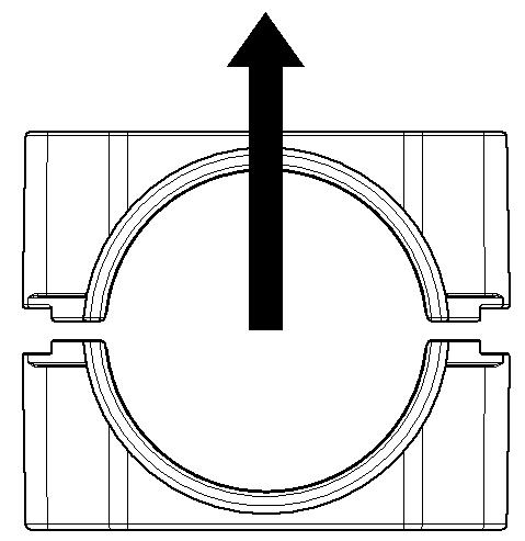
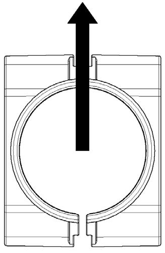
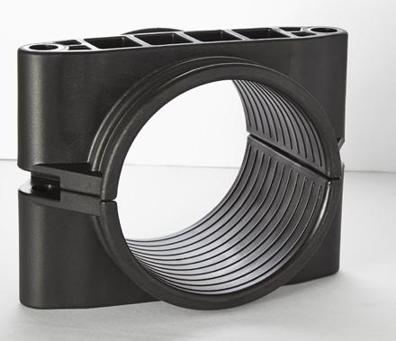
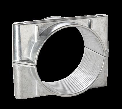
SOLUS CLAMP
EU Design Reg No: 008307425
UK Design Reg No: 90083074250001
Î RANGE ACOMODATES Ø19 - Ø75MM CABLES
Î SUITABLE FOR INDOOR AND OUTDOOR USE
Î SHORT CIRCUIT AND MECHANICALLY TESTED IN ACCORDANCE TO IEC 61914
Î SINGLE OR TWIN BOLT FIXING OPTIONS
Î MANUFACTURED IN A HIGH STRENGTH LSF GLASS FILLED NYLON OR NON GLASS REINFORCED POLYMER
Î FIXINGS ARE NOT SUPPLIED AS STANDARD BUT ARE AVAILABLE ON REQUEST

SINGLE FIXING STYLE POLYMERIC LINER CAN BE SUPPLIED
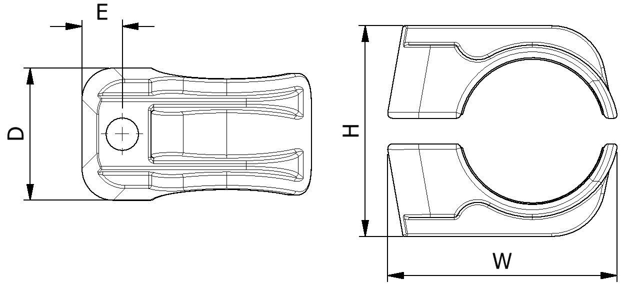
PART NO. CABLE RANGE LINER SIZE (mm) CABLE RANGE WITH LINER DIMENSIONS AXIAL LOAD (KN) LATERAL LOAD - HORIZONTAL (KN) LATERAL LOAD - VERTICAL (kN) WEIGHT (g) SINGLE FIXING TWIN FIXING SINGLE FIXING TWIN FIXING SINGLE FIXING TWIN FIXING MIN Ø (mm) MAX Ø (mm) MIN Ø (mm) MAX Ø (mm) WHDAPØ SL25-38GFN25383193210080602460M120.91.2456.510285 SL36-52GFN36523304611695 60 2475M121.21.845.5610356 SL49-75GFN497534369138124 60 2695M121.61.64106.59485 SL25-38LSF25383193210080602460M121.11.36.571025232 SL36-52LSF36523304611695 60 2475M121.11.868925287 SL49-75LSF497534369138124 60 2695M121.11.16810.526395
TWIN FIXING STYLE 16
NOTE: FOR CLAMP WITH LINER ADD ‘L’ SUFFIX E.G. SL25-38GFNL.
TESTING SUMMARY
Solus clamps have been tested in line with the international standard ‘Cable Cleats for Electrical Installations’ IEC 61914:2021. Typical results are detailed below, please note that these testing values are maximums and safety factors appropriate to your application should be used.
CLEATS AT 300MM INTERVALS
157kA (REPORT No. PDL22.079.02)
CABLE OD = Ø35mm PHASE SPACING = 125mm
NOTE: THE WITH LINER VERSION HAS A LOWER RATING TO THE STANDARD VERSION AS FOLLOWS: 1)TEMPERATURE RANGE OF -60 to +85°C
2)AXIAL PERFORMANCE LOWER THAN STANDARD VERSION, CONTACT ELLIS FOR FURTHER INFORMATION..


164kA (REPORT No. PDL-22.079.01)
CABLE OD = Ø35mm PHASE SPACING = 125mm
LATERAL LOAD ‘VERTICAL’ DIRECTION
LATERAL LOAD ‘HORIZONTAL’ DIRECTION
PRODUCT CAN BE STACKED FLAT USING HEX RECESS ON BASE OF PRODUCTREFER TO INSTALLATION INSTRUCTIONS

This information is subject to change without notice. The information provided has been generated in laboratory conditions and as such results in use may vary. PROPERTY CLASSIFICATION CLAUSE IEC 61914 UNITS / CLASSIFICATION TEST DATA LSF GFN CLEAT TYPE 6.1.2 NON-METALLICTEMP. FOR PERMAMENT APPLICATION 6.2 °C -60 to +60 -60 to +120 IMPACT RATING 6.3.5 VERY HEAVY PASS FLAME PROPAGATION TEST 10.0, 10.1 APPLICATION TIME ≥30S PASS AXIAL LOAD RATING 6.4.3, 9.4 NEWTONS (N) SEE TABLE ON PAGE 16 SEE TABLE ON
16 LATERAL LOAD RATING6.4.2, 9.3 NEWTONS (N) SEE TABLE ON PAGE 16 SEE TABLE ON PAGE 16 RESISTANCE TO ELECTROMECHANICAL FORCE (SHORT CIRCUIT TESTING) 6.4, 6.4.5, 9.5
PAGE
ONE SHORT CIRCUIT)
(WITHSTANDING MORE THAN
17
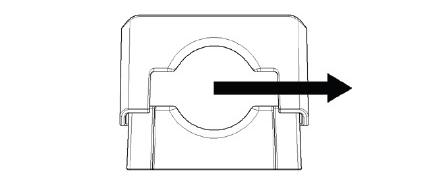
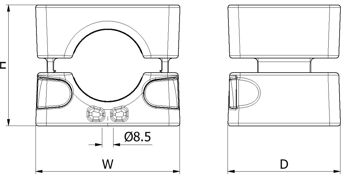
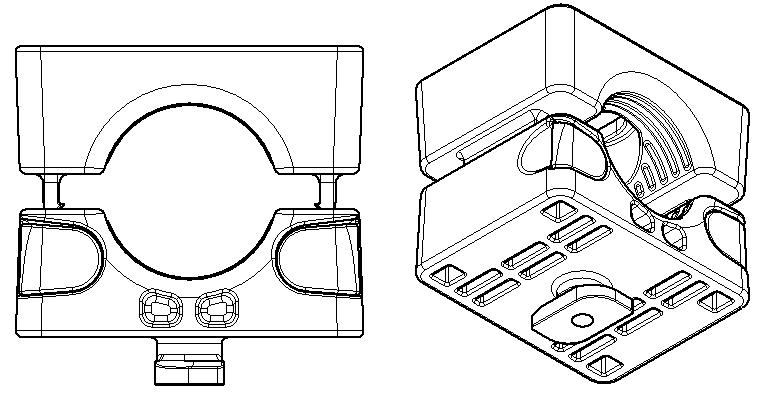
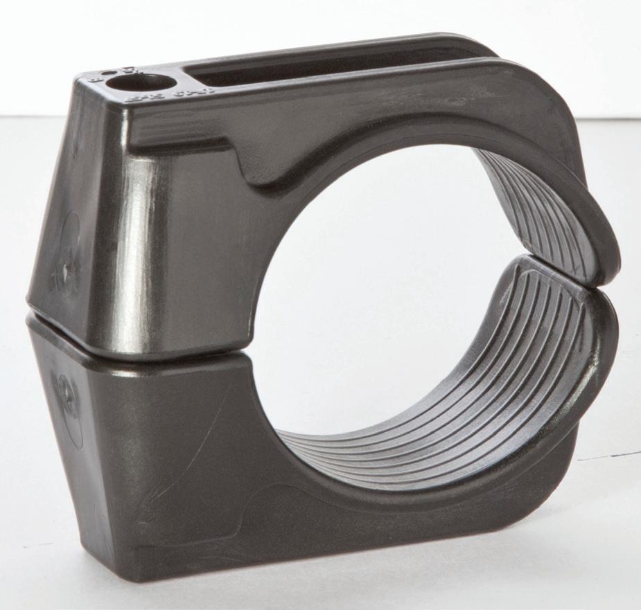
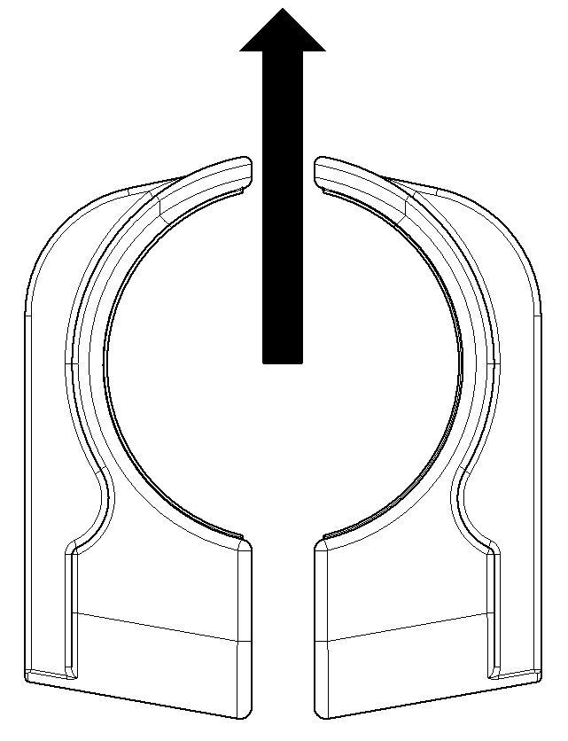
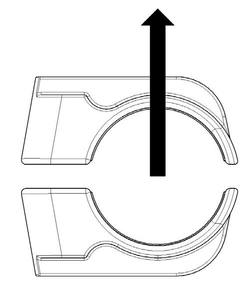
NO BOLTS CLEAT ™
Patent Pending (Application Number 1804174.9)
Î FULLY POLYMERIC CONSTRUCTION ELIMINATES THE RISK OF SNAGGING CABLE ON FIXING BOLTS
Î “NO TOOLS NEEDED” DESIGN ALLOWS FOR FAST INSTALLATION
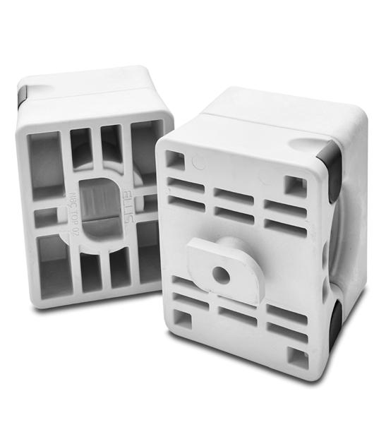
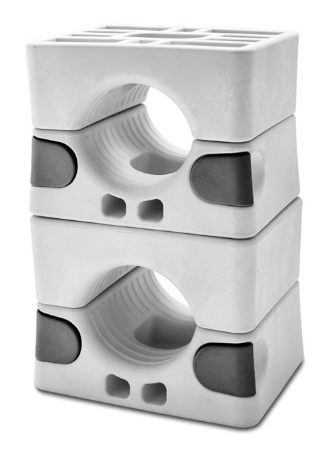
Î PRODUCT CAN BE STACKED THREE CLAMPS HIGH USING TWIST FOOT FEATURE
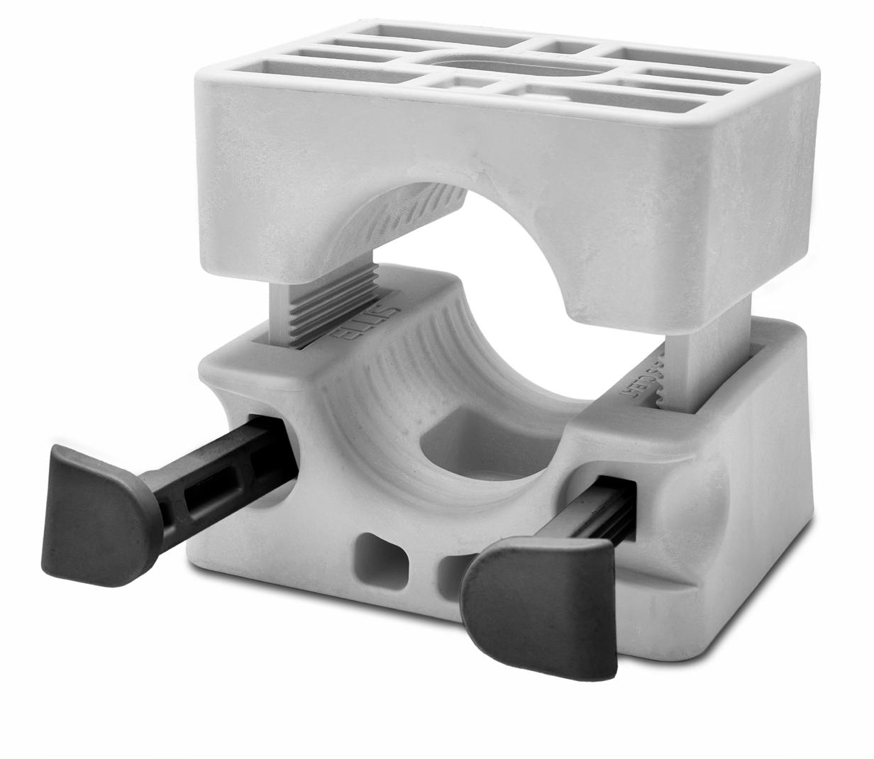
Î SHORT CIRCUIT AND MECHANICALLY TESTED TO IEC 61914
0111/120321NBC18-22TF (for 18-22mm cables)
0111/120322NBC20-26TF (for 20-26mm cables)
0111/120323NBC24-30TF (for 24-30mm cables)
0111/120324NBC28-34TF (for 28-34mm cables)
0111/120325NBC32-39TF (for 32-39mm cables)
0111/120133NBC37-47TF (for 37-47mm cables)
0111/120134NBC45-55TF (for 45-55mm cables)
PART NO. CABLE RANGE DIMENSIONS (mm) FIXING HOLES WEIGHT (g) W H D NBC18-2218 - 221099190 1 x M8830 NBC20-2620 - 261099190 1 x M8815 NBC24-3024 - 30 1099190 1 x M8808 NBC28-3428 - 341099190 1 x M8801 NBC32-3932 - 391099190 1 x M8792 NBC37-4737 - 471099190 1 x M8758 NBC45-55*45 - 551099185 1 x M8675 PADS NO. ELLIS PART NO.
PRODUCT CAN BE STACKED A MAXIMUM OF THREE HIGH BY USING THE TWIST FOOT VARIANT. THIS VERSION LOCKS INTO THE RECESS PROVIDED IN THE TOP OF THE CLAMPS.
DUE TO THE TOLERANCES OF STANDARD UNISTRUT PROFILE, ELLIS RECOMMEND USING FIXINGS TO FASTEN THE CLAMP TO THE CHANNEL.
FOR THE TWIST FOOT VERSION ADD A 'TF' SUFFIX E.G. NBC18-22TF
18
NOTE: THE CLEAT RANGE IS COVERED BY A SET OF INSERTS THAT SIT INSIDE THE MAIN BODY, THEREFORE ALL OUTSIDE DIMENSIONS ARE THE SAME. *NBC45-55 DOES NOT USE INSERTS.
TESTING SUMMARY
No Bolts Cleat has been tested in line with the International Standard of ‘Cable Cleats for Electrical Installations’ IEC 61914: 2015. Typical results below.
CLEATS AT 300MM INTERVALS (WITHSTANDING MORE THAN ONE SHORT CIRCUIT)
101kA (REPORT No. PDL16.106)
PHASE SPACING = 110mm CABLE OD= Ø36mm
71kA (REPORT No. PDL-16.106)
CLEATS AT 300MM INTERVALS (WITHSTANDING MORE THAN ONE SHORT CIRCUIT)
TESTED IN STACKED FORMATION
PHASE SPACING = 75mm CABLE OD= Ø36mm
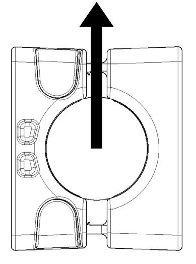
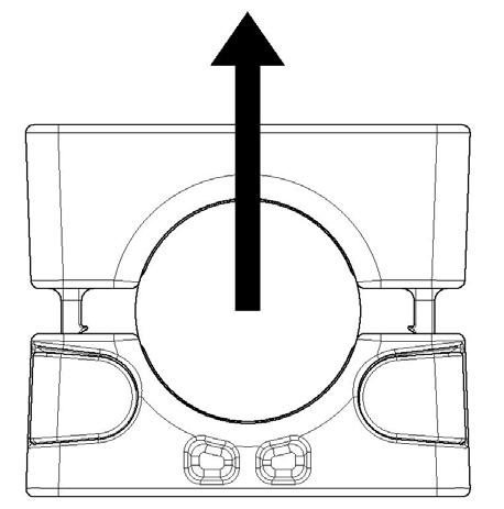
LATERAL LOAD 'VERTICAL’ DIRECTION
LATERAL LOAD 'HORIZONTAL' DIRECTION
This information is subject to change without notice. The information provided has been generated in laboratory conditions and as such results in use may vary. PROPERTY CLASSIFICATION CLAUSE IEC 61914 UNITS / CLASSIFICATION TEST DATA CLEAT TYPE 6.1.2 POLYMERICTEMP. FOR PERMANENT APPLICATION 6.2 °C -40 to +60 IMPACT RATING 6.3.5 VERY HEAVY PASS FLAME PROPAGATION TEST 10.0, 10.1 APPLICATION TIME ≥30s PASS AXIAL LOAD RATING 6.4.3, 9.4 NEWTONS (N) REFER TO ELLIS LATERAL LOAD RATING 6.4.2, 9.3 NEWTONS (N) REFER TO ELLIS
TO ELECTROMECHANICAL FORCE (SHORT CIRCUIT TESTING) 6.4, 6.4.5, 9.5
RESISTANCE
TO ELECTROMECHANICAL FORCE (SHORT CIRCUIT TESTING) 6.4, 6.4.5, 9.5
RESISTANCE
NO BOLTS CLEAT IS A NETWORK RAIL APPROVED PRODUCT. EXAMPLE PADS NUMBER (NBC45-55): 011/120134
19
*TESTING CARRIED OUT ON NBC45-55 ONLY
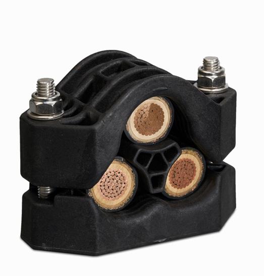
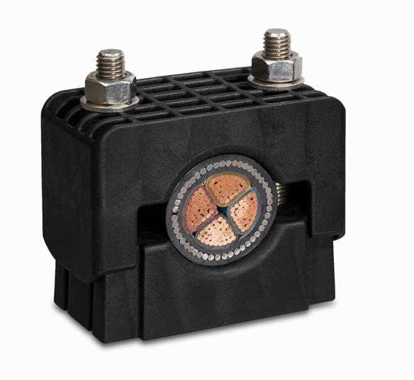
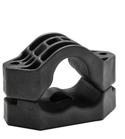
2F+ CABLE CLAMPS
UK Design Reg. No: 355854
Î 2 HOLE CLAMPS MANUFACTURED IN LSF NYLON OR STANDARD POLYPROPYLENE

Î ROBUST DESIGN OFFERS GOOD RESISTANCE TO CABLE FORCES
Î CLAMPING RANGE OF Ø32 - Ø168MM ACHIEVED ACROSS 18 SIZES
Î SHORT CIRCUIT AND MECHANICALLY TESTED TO IEC 61914
Î FIXINGS ARE NOT SUPPLIED AS STANDARD BUT ARE AVAILABLE ON REQUEST
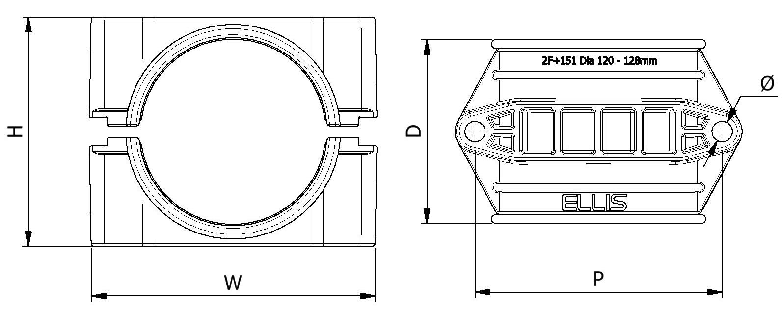
TO SPECIFY MATERIAL ADD SUFFIX TO PART NO. E.G. 2F+07LSF A CLAMP MANUFACTURED IN LONDON UNDERGROUND APPROVED MATERIAL CAN BE SUPPLIED ON REQUEST. CONTACT ELLIS FOR FURTHER DETAILS. PART NO. CABLE RANGE LINER THICKNESS (mm) CABLE RANGE WITH LINER DIMENSIONS (mm)WEIGHT (g) PACK QTY AXIAL LOAD LATERAL LOADHORIZONTAL LATERAL LOADVERTICAL MIN Ø (mm) MAX Ø (mm) MIN Ø (mm) MIN Ø (mm) WHDPØLSFB LSFBLSFBLSFB 2F+07384633240926854682 x M10917325200N150N1.75kN1.5kN15kN4kN 2F+084651340451037654792 x M101108125200N150N1.75kN1.5kN15kN4kN 2F+095157345511038254792 x M101199525200N150N1.75kN1.5kN15kN4kN 2F+105764351581038954792 x M101238925200N150N1.75kN1.5kN15kN4kN 2F+1164703586413095541062 x M1015711610200N150N1.75kN1.5kN15kN4kN 2F+1200707646268128101751042 x M1019016010500N500N5kN1.5kN15kN6kN 2F+1201768346875135107751112 x M1020717410500N500N5kN1.5kN15kN6kN 2F+1202839047582143115751192 x M1022918810500N500N5kN1.5kN15kN6kN 2F+1319097580871651221001382 x M1242333652kN700N5kN3kN18.5kN10kN 2F+13297105587951711301001442 x M1244135552kN700N5kN3kN18.5kN10kN 2F+1411051125951021781371001512 x M1251038252kN700N5kN3kN18.5kN10kN 2F+14211212051021101871461251602 X M1262249652kN1.3kN5kN4.5kN18.5kN8kN 2F+15112012851101181961561251682 X M1271653752kN1.3kN5kN4.5kN18.5kN8kN 2F+15212813551181252031651251762 X M1277257952kN1.3kN5kN4.5kN18.5kN8kN 2F+16113514451251342221771501902 X M16110983152.5kN2kN30kN8kN40kN15kN 2F+16214415251341422321871502002 X M16120390252.5kN2kN30kN8kN40kN15kN 2F+17115216051421502421981502102 X M16130297652.5kN2kN30kN8kN40kN15kN 2F+17216016851501582522091502202 X M161403105252.5kN2kN30kN 8kN40kN15kN 20
TESTING SUMMARY
2F+ Clamps have been tested in line with the International Standard ‘Cable Cleats for Electrical Installations’ IEC 61914:2015. Typical results are detailed below, please note that these testing values are maximums and safety factors appropriate to your application should be used.
2F+07LSF CLEATS AT 600MM INTERVALS (WITHSTANDING ONE SHORT CIRCUIT)
CLEATS AT 1M INTERVALS (WITHSTANDING MORE THAN ONE SHORT CIRCUIT)
No. PDL-18.071.1)
No. PDL-15.025.1) (BASED ON IEC 61914: 2009)
OD= Ø117mm
SPACING = 200mm
The LUL version of 2F+ Clamps are compliant with the requirements of LUL-1085. Product register number 364.
This information is subject to change without notice. The information provided has been generated in laboratory conditions and as such results in use may vary.
LATERAL LOAD ‘VERTICAL’ DIRECTION LATERAL LOAD ‘HORIZONTAL’ DIRECTION LONDON UNDERGROUND
The test data provided above is for the standard version only, for test data with the liner option please contact Ellis.
PROPERTY CLASSIFICATION CLAUSE IEC 61914 UNITS / CLASSIFICATION TEST DATA CLEAT TYPE 6.1, 6.1.3 POLYMERICTEMP. FOR PERMANENT APPLICATION 6.2 °C LSF: -40 to +60 B:-40 to +40 UV RESISTANCE 6.5.1.2 XENON ARC METHOD A PASS IMPACT RATING 6.35 VERY HEAVY PASS FLAME PROPAGATION TEST 10.0, 10.1 APPLICATION TIME ≥30s LSF: PASS B: NOT COMPLIANT AXIAL LOAD RATING 6.4.3, 9.4 NEWTONS (N) REFER TO THE DATA TABLE OPPOSITE LATERAL LOAD RATING 6.4.2, 9.3 NEWTONS (N) REFER TO THE DATA TABLE OPPOSITE RESISTANCE TO ELECTROMECHANICAL FORCE (SHORT CIRCUIT TESTING) 6.4, 6.4.5, 9.5
80.2kA (REPORT
CABLE
PHASE
RESISTANCE TO ELECTROMECHANICAL FORCE (SHORT CIRCUIT TESTING) 6.4, 6.4.5, 9.5 2F+142LSF
113kA (REPORT
CABLE
21
OD= Ø36mm
SPACING = 100mm
PHASE
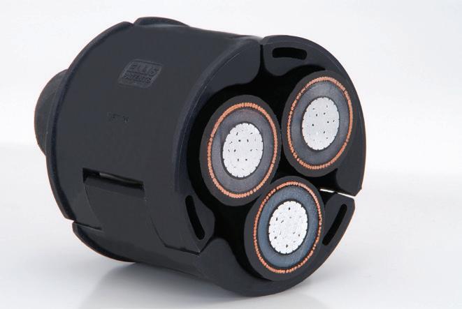
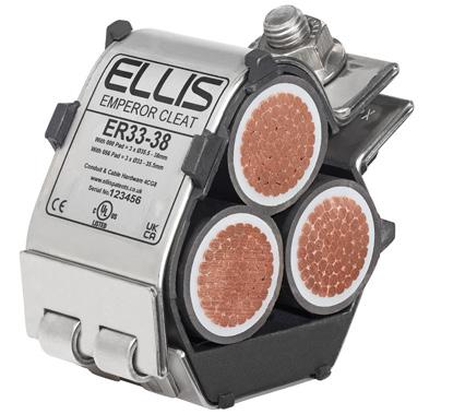
TRIPLEX CABLE SURROUND

UK (2514384), EUROPEAN (2806198) and US (9,404,605) Patent
Î TRIPLEX CABLE SURROUND OVERCOMES THE TWIST IN TRIPLEX CABLE TO ALLOW THE CABLE TO BE CLEATED AT ANY POINT ALONG ITS LENGTH
Î ADAPTOR MANUFACTURED IN A LSF V0 POLYMER
Î CAN BE USED WITH EMPEROR SINGLE, VULCAN+, 2F+ AND 2A CLEATS
Î REFER TO INDIVIDUAL PRODUCT DATA SHEETS FOR PERFORMANCE TO IEC 61914
Î SOLD SEPARATELY TO THE CLEATS AS STANDARD BUT CAN BE PROVIDED ASSEMBLED INSIDE THE CLEAT ON REQUEST
SFT31 / SFT2F+31283462 / 8487 / 125
SFT36 / SFT2F+36333962 / 84113 / 160
SFT43 / SFT2F+43 394762 / 109140 / 272
SFT51 / SFT2F+51475562 / 134212 / 447
NOTE:
SFT2F+XX part numbers refer to a deeper SFT+ moulding to be used with 2F+ and 2A clamps, see table for more detail.
NOTE: ‘CABLE RANGE’ REFERS TO THE OUTSIDE DIAMETER OF THE INDIVIDUAL CABLES INSIDE THE TRIPLEX BRAID

THIS PRODUCT HAS BEEN SHORT CIRCUIT TESTED IN LINE WITH EN 50368:


CONFIGURATION: 2F+LSF CLEAT WITH SFT
PEAK CURRENT: 76kA
CLEAT SPACING: 600mm
PART NO. CABLE RANGE DEPTH (mm) WEIGHT (g) MINMAX SFT26 24286267.3
22
CABLE CLEAT SELECTION DETAIL FOR CLEATS
THE TRIPLEX CABLE SURROUND
***FOR PART NUMBERS IN RED THE WIDER SFT2F+ NEEDS TO BE USED TO SUIT THE INCREASED DEPTHS OF THE CLAMPS***
CABLE OD (mm) SFT OD (mm) ADAPTOR TYPE VULCAN+ EMPEROR 2F + CLAMP 2A CLAMP 24 56 SFT26 VRT+03 ES51-59 2F+09 2A-09 25 58 SFT26 VRT+03 ES51-59 2F+10 2A-10 26 59 SFT26 VRT+03 ES51-59 2F+10 2A-10 27 61 SFT26 VRT+04 ES58-66 2F+10 2A-10 28 63 SFT26 VRT+04 ES58-66 2F+10 2A-10 28 64 SFT31 VRT+05 ES58-66 2F+11 2A-11 29 66 SFT31 VRT+05 ES65-73 2F+11 2A-11 30 68 SFT31 VRT+05 ES65-73 2F+11 2A-11 31 70 SFT31 VRT+06 ES65-73 2F+1200 2A-1200 32 71 SFT31 VRT+06 ES65-73 2F+1200 2A-1200 33 73 SFT31 VRT+06 ES65-73 2F+1200 2A-1200 34 75 SFT31 VRT+06 ES73-85 2F+1200 2A-1200 33 76 SFT36 VRT+06 ES73-85 2F+1201 2A-1201 34 78 SFT36 VRT+06 ES73-85 2F+1201 2A-1201 35 80 SFT36 VRT+07 ES73-85 2F+1201 2A-1201 36 82 SFT36 VRT+07 ES73-85 2F+1201 2A-1201 37 83 SFT36 VRT+07 ES73-85 2F+1202 2A-1202 38 84 SFT36 VRT+07 ES73-85 2F+1202 2A-1202 39 86 SFT36 VRT+08 ES84-94 2F+1202 2A-1202 39 88 SFT43 VRT+08 ES84-94 2F+1202 2A-1202 40 89.5 SFT43 VRT+08 ES84-94 2F+1202 2A-1202 41 93 SFT43 VRT+08 ES84-94 2F+131 2A-131 42 94 SFT43 VRT+09 ES84-94 2F+131 2A-131 43 95 SFT43 VRT+09 ES94-118 2F+131 2A-131 44 97 SFT43 VRT+09 ES94-118 2F+131 2A-131 45 99 SFT43 VRT+10 ES94-118 2F+132 2A-132 46 102 SFT43 VRT+10 ES94-118 2F+132 2A-132 47 104.5 SFT43 VRT+11 ES94-118 2F+132 2A-132 47 105 SFT51 VRT+11 ES94-118 2F+132 2A-132 48 107 SFT51 VRT+11 ES94-118 2F+141 2A-141 49 110 SFT51 VRT+12 ES94-118 2F+141 2A-141 50 112 SFT51 VRT+12 ES94-118 2F+141 2A-141 51 114 SFT51 VRT+12 ES94-118 2F+142 2A-142 52 117 SFT51 VRT+12 ES94-118 2F+142 2A-142 53 119.5 SFT51 VRT+13 ES118-130 2F+142 2A-142 54 121 SFT51 VRT+13 ES118-130 2F+151 2A-151 55 123.5 SFT51 VRT+13 ES118-130 2F+151 2A-151
TO BE USED
This information is subject to change without notice. The information provided has been generated in laboratory conditions and as such results in use may vary. 23
WITH
1F CABLE CLAMPS
UK Design Reg. No: 355854
Î 1 HOLE CLAMPS MANUFACTURED IN LSF NYLON OR STANDARD POLYPROPYLENE
Î ACCOMMODATES Ø10MM - Ø57MM CABLES ACROSS 10 SIZES
Î SHORT CIRCUIT AND MECHANICALLY TESTED TO IEC 61914
Î FIXINGS ARE NOT SUPPLIED AS STANDARD BUT ARE AVAILABLE ON REQUEST
Î OPTIONAL LSF POLYMERIC LINER AVAILABLE
PART NO. MATERIAL SUFFIX CABLE RANGE (mm) DIMENSIONS (mm) FIXING HOLES PACK QTY WEIGHT (g) W H D E B LSF LUL MIN MAX 1F-10 B/LSF/LUL 10 13 37.8 30.0 41.4 10.2 1 x M10 100 14.6 19.6 23.8 1F-11 B/LSF/LUL 13 16 41.2 33.0 41.4 10.4 1 x M10 100 17.0 23.0 27.7 1F-12 B/LSF/LUL 16 19 44.3 36.0 41.4 10.7 1 x M10 100 19.6 26.4 32.0 1F-13 B/LSF/LUL 19 23 48.2 40.0 41.4 10.9 1 x M10 100 22.4 30.2 36.5 1F-14 B/LSF/LUL 23 27 52.2 44.0 41.4 11.3 1 x M10 100 25.8 34.6 42.0 1F-15 B/LSF/LUL 27 32 57.1 49.0 41.4 11.6 1 x M10 100 29.2 39.0 47.6 1F-16 B/LSF/LUL 32 38 63.1 55.0 41.4 12.1 1 x M10 100 34.2 46.2 55.7 1F-17 B/LSF/LUL 38 46 71.3 66.0 41.4 12.9 1 x M10 50 47.8 64.0 77.9 1F-18 B/LSF/LUL 46 51 77.3 73.0 41.4 13.5 1 x M10 50 54.0 73.2 88.0 1F-19 B/LSF/LUL 51 57 83.2 78.0 41.4 13.9 1 x M10 50 59.0 80.4 96.2 24
TESTING SUMMARY
1F Clamps have been tested in line with the International Standard ‘Cable Cleats for Electrical Installations’ IEC 61914:2015. Typical results are detailed below, please note that these testing values are maximums and safety factors appropriate to your application should be used.
AT 300MM INTERVALS (WITHSTANDING MORE THAN ONE SHORT CIRCUIT)
No. PDL17.137.2)
LATERAL LOAD ‘VERTICAL’ DIRECTION
LATERAL LOAD ‘HORIZONTAL’ DIRECTION
APPROVALS:
THE LUL VERSION OF THE 1F ONE HOLE CABLE CLAMPS ARE COMPLIANT WITH THE REQUIREMENT OF LONDON UNDERGROUND STANDARD 1-085. PRODUCT REGISTER NO. 363.
This information is subject to change without notice. The information provided has been generated in laboratory conditions and as such results in use may vary.
PROPERTY CLASSIFICATION CLAUSE IEC 61914 UNITS / CLASSIFICATION TEST DATA LSF B CLEAT TYPE 6.1.2 POLYMERIC -TEMP. FOR PERMANENT APPLICATION 6.2 °C -40 to +60 -40 to +40 UV RESISTANCE 6.5.1.2 XENON ARC METHOD A PASS PASS IMPACT RATING 6.3.5 VERY HEAVY REFER TO ELLIS REFER TO ELLIS FLAME PROPAGATION TEST 10.0, 10.1 APPLICATION TIME ≥30s PASS NOT COMPLIANT AXIAL LOAD RATING 6.4.3, 9.4 NEWTONS (N) REFER TO ELLIS REFER TO ELLIS LATERAL LOAD RATING 6.4.2, 9.3 NEWTONS (N) REFER TO ELLIS REFER TO ELLIS RESISTANCE TO ELECTROMECHANICAL FORCE (SHORT CIRCUIT TESTING) 6.4, 6.4.5, 9.5 CLEATS
10.4kA (REPORT
(IEC
PHASE SPACING
CABLE OD= Ø36mm NOT SHORT
25
61914:2015)
= 100mm
CIRCUIT TESTED
IEC 61914 – CABLE CLEATS FOR ELECTRICAL INSTALLATIONS
IEC 61914 specifies requirements and tests for cable cleats and intermediate restraints used for securing cable in electrical installations. Cable cleats provide resistance to electromechanical forces. Products achieve conformance to the standard after being subjected to a range of tests.
The tests are designed to simulate real world installation conditions and provide designers with data that can be used to aid with system design. Relevant sections of the standard and Ellis’ testing regime are detailed below.
1. CLEAT TYPE
The three cleat classifications are:
Î METALLIC
Î COMPOSITE
Î NON-METALLIC
Î 1. CLEAT TYPE
Î 2. TEMPERATURE FOR PERMANENT APPLICATION
Î 3. UV RESISTANCE
Î 4. CORROSION RESISTANCE
Î 5. IMPACT RATING
Î 6. FLAME PROPAGATION TEST
Î 7. AXIAL LOAD RATING
Î 8. LATERAL LOAD RATING TEST
Î 9. RESISTANCE TO ELECTROMECHANICAL FORCE
Metallic cleats are all metal, composite cleats contain a combination of metallic and polymeric parts and non-metallic cleats contain no metallic parts and are fully polymeric.
2. TEMPERATURE FOR PERMANENT APPLICATION
DEFINITION:
The ambient temperature range that a cleat is capable of operating within.
IEC 61914 provides set temperatures to specify against. These values are ambient and are not representative of the expected maximum cable conductor temperature.
METALLIC CLEAT NON METALLIC CLEAT COMPOSITE CLEAT MINIMUM TEMPERATURE °C +5 -5 -15 -25 -40 -60 MAXIMUM TEMPERATURE °C +40 +60 +85 +105 +120 26
3. UV RESISTANCE
Composite and non-metallic type cleats are subject to UV resistance testing. Samples are exposed to a minimum of 700 hours of ‘Xenon-arc’ UV light in accordance with ISO 48922:2006. Products are deemed to have passed if they show no signs of cracking or degradation to normal vision and pass the requirements of the impact test.
Cleats deemed as being UV resistant are certified only to the requirements of IEC 61914 and as such their classification may not extend to harsher criteria (e.g. desert installation). Ellis have UV testing capabilities in house and can test conditions which are more onerous than detailed in IEC 61914.

4. CORROSION RESISTANCE:
Metallic or composite type cleats are subject to corrosion resistance testing. Any metal components that are non-ferrous (e.g. aluminium) or are ferrous but contain more than 16% chromium (e.g. 316L stainless steel) need not be tested and are assumed to meet the classification for high resistance to corrosion. Any metallic components that do not meet this criteria are subject to a minimum of 192 hours of salt spray according to ISO9227 (for ‘high corrosion classification’). After the exposure the cleats are visually checked and deemed to have passed if ‘no red rust visible to normal or corrected vision.’
Similar to the UV test data the classification of ‘high corrosion resistance’ is limited to the criteria of the standard and therefore for applications in harsh environments contact Ellis for guidance.

IN ADDITION TO THE CORROSION TESTING TO IEC 61914 ELLIS CARRIES OUT EXTENDED TESTING ON ITS OUTDOOR WEATHERING STATION.
5. IMPACT RATING
A cleat’s impact rating is established by dropping a set weight onto a product from a set height. The rating relevant to the weight and height characteristics are detailed below. For composite and non-metallic cleats this is conducted at the minimum declared temperature for the cleats. For metallic cleats the testing is done at room temperature. A cleat is deemed to have passed providing there is no damage that would affect the cleats load holding capability.
The impact test is reflective of the resistance to items dropping on it whilst on site, or it being dropped during install.
 ELLIS’ IN HOUSE UV WEATHERING TEST STATION
CLASSIFICATIONNOMINAL IMPACT ENERGY (J)EQUIVALENT MASS (KG)HEIGHT (MM) Very light 0.5 0.25 200 Light 1.0 0.25 400 Medium 2.0 0.5 400 Heavy 5.0 1.7 300 Very Heavy 20.0 20.0 400 27
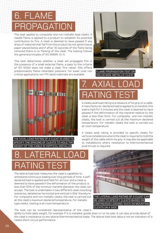
6. FLAME PROPAGATION
This test applies to composite and non-metallic type cleats. A needle flame is applied to a product to establish its potential contribution to fire. A cleat is deemed to have passed if any drips of material that fall from the product do not ignite tissue paper placed below and if after 30 seconds of the flame being removed there is no flaming of the cleat. The testing follows the general principles of IEC 60695-11-5.
This test determines whether a cleat will propagate fire in the presence of a small external flame, a pass to the criteria of IEC 61914 does not make a cleat ‘fire rated’. Ellis offers predominantly flame-retardant polymers, for lower cost non critical applications non FR rated materials are available.


7. A XIAL LOAD RATING TEST
A cleats axial load rating is a measure of its grip on a cable. A manufacturer-declared load is applied to a mandrel, this load is held for 5 minutes and the cleat is deemed to have passed if the deformation of the mandrel relative to the cleat is less than 5mm. For composite and non-metallic cleats, the test is carried out at the maximum declared temperature. For metallic cleats the test is carried out at room temperature.
THE AXIAL LOAD RATING OF A CLEAT IS USED TO SPECIFY THE SPACING OF CLEATS TO HOLD THE WEIGHT OF THE CABLE IN VERTICAL INSTALLS
A cleats axial rating is provided to specify cleats for vertical installations where the cleat is required to hold the weight of the cable within its grip. It may also be applicable to installations where resistance to thermomechanical axial thrust is required.

8. L ATERAL LOAD RATING TEST
The lateral load test measures the cleat’s capability to withstand continuous loading over long periods of time. A selfdeclared load is applied and held for an hour and a cleat is deemed to have passed if the deformation of the product is less than 50% of the minimum mandrel diameter the cleat can accept. The test is undertaken in two different cleat mounting scenarios, detailed as horizontal and vertical in Ellis’ literature. For composite and non-metallic cleats, the test is carried out at the cleat’s maximum declared temperature, for metallic type cleats, testing is at room temperature.
THE LATERAL LOAD RATING OF A CLEAT CAN BE USED TO SPECIFY CLEATS BASED ON CONTINUOUS LOADING, SUCH AS MOUNTING CLEATS ON A SIDE.
The test can be considered representative of the cleat’s ability to hold cable weight, for example if it is installed upside down or on its side. It can also provide detail of the cleat’s resistance to any lateral thermomechanical loads. The lateral load test data is not an indication of a cleats short circuit performance.
FLAME PROPAGATION TEST ON SOLUS NON-METALLIC CLEAT.
28
9. RESISTANCE TO ELECTROMECHANICAL FORCE
Perhaps the most important function of a cable cleat is to withstand the electromechanical forces generated during a short circuit. IEC 61914 short circuit testing specifies a three phase fault with one cable per phase. One end of the cables is connected to a three phase supply and the other end to a short-circuit busbar connecting all three phases. Some key requirements of the testing are as follows:
Î The short circuit peak current is carried out to a manufacturer declared peak current and lasts no less than 0.1s.
Î The test cable must be unarmoured single core 600 V /100 V stranded copper conductor cable with a 35(±5 mm or 50 (±5)mm outside diameter.
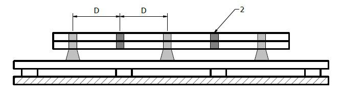
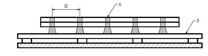
Key Description
1 Cable Cleats
2 Intermediate Restraints
3 Mounting Surface

D Lineal Spacing
Î Testing is carried out at the prevailing ambient temperature of the laboratory.
Î A minimum of 5 test cleats are to be used for fully cleated tests and at least 4 cleats and 3 intermediate straps must be used for cleat-strap installs, as displayed above.
Î The cable formation tested must either be trefoil or flat formation, see below:
 EXTRACT FROM IEC INTERMEDIATE RESTRAINT TEST LAYOUT.
29
After one short circuit a cleat is deemed to have passed if:
Î There is no failure that will affect the cleat or intermediate straps from holding the cables in place.
Î The cleats and intermediate straps shall be intact with no missing parts including all devices used to secure cleats to the mounting surface.
Î There shall be no cuts or damage visible to normal or corrected vision to the outer sheath of each cable caused by the cleats or intermediate straps.
A manufacturer can decide to test a second short circuit. The pass criteria for a cleat withstanding two short circuits is as follows:
Î The pass criteria for one short circuit applies.
Î The test rig must pass a 2.8kV d.c or 1.0kV a.c 60 second voltage withstand test administered between the cable cores and the mounting frame. With the cable jackets and mounting frame being pre-wetted to facilitate a current leakage path.

Ellis has over 20 years’ experience of short circuit testing. Our experience in the field precedes the inception of National and International Cable Cleat standards. The company has carried out over 1,000 short circuit tests in numerous test labs around the world to the requirements of IEC 61914 as well as specialised testing to customer requirements.

30
TYPICAL TESTING TO IEC 61914 AND BESPOKE TESTING OF A HV TEST RIG TO A CUSTOMER’S SPECIFICATION.
NOTES
31
Ellis Patents Ltd High Street, Rillington, Malton North Yorkshire YO17 8LA United Kingdom T. +44 (0)1944 758395 F. +44 (0)1944 758808 sales@ellispatents.co.uk www.ellispatents.co.uk