Chapter 1 • Raspberry Pi Pico Hardware
Chapter 1 • Raspberry Pi Pico Hardware 1.1 Overview The Raspberry Pi Pico is a single-board microcontroller module developed by the Raspberry Pi Foundation. This module is based on the RP2040 microcontroller chip. In this Chapter we will be looking at the hardware details of the Raspberry Pi Pico microcontroller module in some detail. From here on, we will be calling this microcontroller module "Pico" for short, in for appreciation and recognition though of its official name: Raspberry Pi Pico.
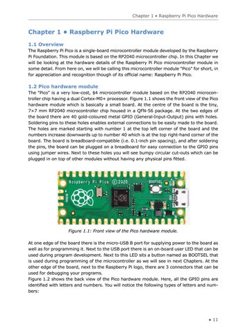
1.2 Pico hardware module The "Pico" is a very low-cost, $4 microcontroller module based on the RP2040 microcontroller chip having a dual Cortex-M0+ processor. Figure 1.1 shows the front view of the Pico hardware module which is basically a small board. At the centre of the board is the tiny, 7×7 mm RP2040 microcontroller chip housed in a QFN-56 package. At the two edges of the board there are 40 gold-coloured metal GPIO (General-Input-Output) pins with holes. Soldering pins to these holes enables external connections to be easily made to the board. The holes are marked starting with number 1 at the top left corner of the board and the numbers increase downwards up to number 40 which is at the top right-hand corner of the board. The board is breadboard-compatible (i.e. 0.1-inch pin spacing), and after soldering the pins, the board can be plugged on a breadboard for easy connection to the GPIO pins using jumper wires. Next to these holes you will see bumpy circular cut-outs which can be plugged in on top of other modules without having any physical pins fitted.
Figure 1.1: Front view of the Pico hardware module. At one edge of the board there is the micro-USB B port for supplying power to the board as well as for programming it. Next to the USB port there is an on-board user LED that can be used during program development. Next to this LED sits a button named as BOOTSEL that is used during programming of the microcontroller as we will see in next Chapters. At the other edge of the board, next to the Raspberry Pi logo, there are 3 connectors that can be used for debugging your programs. Figure 1.2 shows the back view of the Pico hardware module. Here, all the GPIO pins are identified with letters and numbers. You will notice the following types of letters and numbers:
● 11