4 minute read
to manage it

by Grupo Asís

Diode laser overview: how it is done and how to manage it
E. Ruga
Advertisement
Approaching the use of lasers in dentistry requires a preliminary discussion about the technical aspects of this “new” method.
The construction aspects of the recent diode lasers will be briefly described below, focusing attention on their functions and possible clinical implications, so as to guarantee the operator a more effective and aware use experience.
Each medical laser unit consists of several essential components (" 2.1), which are fundamental respectively for the production, emission and transmission of the laser beam.
According to the specific field of application, some units may differ in the type and specifications of the components. Units intended for intensive use and operating at high power ratings, for example, differ in shape, size and technical specifications compared to simpler and cheaper systems designed for applications requiring low power. Fixed systems with larger dimensions still differ in construction characteristics and technical specifications compared to portable and transportable systems.
The diode laser is a semiconductor laser, whose components, now increasingly miniaturized, frequently allow easy transport of the device.
A laser is essentially made up of an active medium, i.e. the element or substance that supplies the atoms, which, invested by energy emitted from an external source (pumping system), will absorb photons, which will transfer electrons from a given energy level to a higher one.1
The pumping system is represented, in the case of a diode laser, by the electric current. The active medium is confined to a structure, called “optical cavity” or “optical resonator”, which will allow the spontaneously emitted photons to trigger the stimulation mechanism and to generate the laser beam, once a certain threshold is exceeded (! 2.1). Each element will be characterized by specific energy levels and the photons emitted will, consequently, be characterized by specific energy, frequency and wavelength.2
" 2.1 Essential components of diode laser
Main unit (including optical cavity and core) Remote control unit Energy source (pumping system) Means of conduction
The optical cavity is able, given its construction specifications, to select the desired wavelength, among the various possible ones, in relation to the element considered (! 2.2).
The diode is made up of several semiconductor elements arranged according to a specific layering.
Among the most used we have gallium-arsenic, suitably doped with aluminum atoms (AlGaAs).
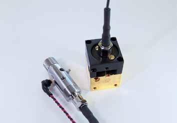
A copper block with gold plating, for better electrical conductivity, is used as a support for mounting the diode (! 2.3). The diode is then joined to the block by the interposition of a thin indium plate (! 2.4), a material with low resistivity, able to improve the behavior of the contact area and the conduction characteristics.
The diode support is, in turn, connected to a specific collimation device, used to align the beam coming out of the diode to the SMA 905 connector, where a connecting fiber capable of reaching an external connection will then be applied (! 2.5).
In the final assembly, a 200 μm fiber (patch cord) is often used to connect the collimated diode to the optical collimating device LIMO (! 2.6), which allows to coher-
Pumping system
MEANS OF CONDUCTION GaAs semiconductor
Optical cavity with EEL emitter Power
Optical cavity/Optical resonator
! 2.1 Constituents of a laser system: pumping system (orange), main unit (blue), means of conduction (yellow).
! 2.3 Support for the integration of the diode. An indium bonding plate (gray color) is visible. ! 2.2 915 nm Multi-Mode diode in C-Mount format.
! 2.4 Diode mounted and screwed on the support block. ! 2.5 Mounted diode solidarized with the collimator.

SMA 905 connector and laser output
Direction adjustment
Adjustment gear Adjustment gear
ently join two laser sources: the 915 nm source (invisible) and the source at 630 nm (red, used as a pointing system).
This last aspect is very important: in infrared and near infrared lasers, the operator is unable to view the real laser beam emitted by the main diode, as it is invisible. To overcome this drawback, the manufacturer usually applies a secondary (pointing) diode.
The function of the secondary diode is to allow the clinician to be able to correctly view the beam projection on the work area (! 2.7). Depending on your manufacturing choices, the pointer can be red, green, blue, or white. The secondary diode does not require high energy, not having a therapeutic function. The nominal power is therefore a few mW.
The patch cord is generally 200 μm to allow you to connect fibers of the same or greater cross-section to the output available to the user.
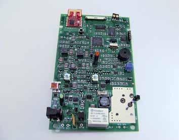
The various components listed must then be connected to the motherboard (! 2.8 and 2.9), so that they can be suitably controlled by a microprocessor, capable of interfacing the entire architecture with the user through specific software.
SMA 905 output available to the user
200 µm patch cord
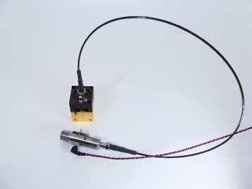
Optical collimation device LIMO
635 nm red diode laser pointer
! 2.6 Path of the laser beam inside the main unit: from the diode to the optical output.
! 2.8 Motherboard of a modern portable diode system. ! 2.7 Detail of the 915 nm C-mount diode and the SMA 905 optical output. The secondary pointer diode that is inserted into the optical output is visible.
! 2.9 Motherboard with assembled diode, patch cord, secondary diode, optical output and cooling fan.