Viscometer Control module – USER MANUAL
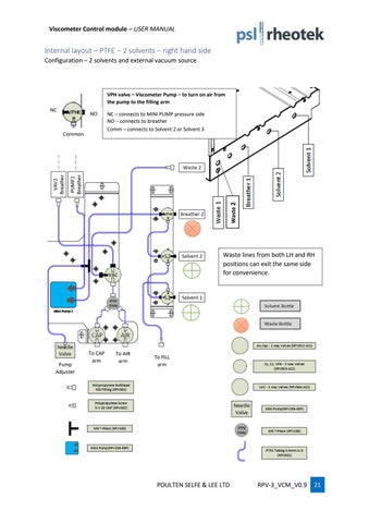
Internal layout – PTFE – 2 solvents – right hand side Configuration – 2 solvents and external vacuum source
VPH valve – Viscometer Pump – to turn on air from the pump to the filling arm NC
NO
Waste 2
Common
NC – connects to MINI PUMP pressure side NO – connects to breather Comm – connects to Solvent 2 or Solvent 3
Waste lines from both LH and RH positions can exit the same side for convenience.
Pump Adjuster
To CAP arm
To AIR arm
To FILL arm
POULTEN SELFE & LEE LTD
RPV-3_VCM_V0.9
21
