27 minute read
The effect of fin sweep angle on a model rocket’s flight: To what extent does the sweep angle of a model rocket’s fin affect its apogee?


Neeve Davies
Peel High School
Rockets are highly inefficient vehicles due to their significant weight and the substantial effects of drag. Model rockets can be used as a cost-effective method to test approaches aimed at reducing these effects, the benefit s of which can be applied also by casual hobbyists. The study examines the extent to which an increase in sweep angle of a model rocket’s swept fins increases its apogee, using both simulated data obtained via Open Rocket and practically obtained data produced by actual launches to draw conclusions. The study finds with 95% certainty that there is a high, statistically significant correlation between sweep angle and apogee, indicative in an r2 value of 0.9356 and a p-value of < 0.0001. The study recognises the significant potential of errors and uncertainties present largely within the practical data but finds that the practically obtained data adequately supports the simulated data.
Literature review
Rockets are highly useful vehicles, with their capacity to contain all of their reaction mass enabling them to carry payloads so far as the relative vacuum of space in order to carry people and scientific equipment into Earth’s orbit and beyond (Newton, 2020). Throughout the years since their development, they are being used increasingly for commercial purposes like situating satellites into orbit which perform a variety of services like GPS, weather forecasting, and radio and internet communications (Union of Concerned Scientists, 2014). There are also emerging opportunities in Australia concerning space exploration since the government has partnerships with NASA concerning fields like radioastronomy as well as in providing launch sites for NASA missions. Additionally, as of 2018, Australia officially has its own space agency. This represents a growing trend to become more ambitious and internationally competitive in regards to the commercialisation of space. Smaller sounding rockets are used professionally for the purposes of scientific research largely involving the upper atmosphere, and easily accessible model rockets are used more commonly as a casual hobby, for rocketry competitions, or for educational purposes. Each form of rocketry, irrespective of its scale, is still an application of the same core principles of science.
A rocket’s flight in atmosphere is affected by four distinct forces, namely weight, thrust, drag, and lift (Benson, 2021). A rocket’s thrust is produced by a combustion reaction which creates a constant buildup of pressure in the engine that is then channelled through the nozzle, utilising Newton’s third law of motion to push the rocket in the desired, opposite direction (Newton, 2020)(Cohen, 2020) (Rohini, et al., 2022). The weight force acts based on a rocket’s mass, which decreases based on the rate through which the engine combusts the fuel and the subsequent release as exhaust of the by-products. The forces of drag and lift are direct products of the rocket’s motion through a fluid, where drag acts in opposition to the motion and lift acts perpendicular to it.
Optimising the efficiency of the rocket involves finding ways to decrease its mass and minimise drag forces, an especially prominent issue for commercial rockets whose mass consists of about 85% fuel for most common chemical propellants (Pettit, 2012). This high ratio of propellant to total mass is due to the fact that every kilogram of fuel requires additional fuel to put the mass of the initial fuel into orbit. This acts in addition to the significant drag it experiences as a result of its high velocity. As such, the overwhelming majority of fuel is consumed simply in getting the rocket into a stable orbit. Therefore, for space exploration to become more efficient and more economically feasible as well as improve the efficacy of more accessible applications of rocketry such as the use of model rockets, it is vital to minimise the weight and the drag forces acting on a rocket.
There are a limited number of studies directly tackling this broad issue, including a 2003 study by Faustino J. Gomez and Risto Miikkulainen that considers the possibility of removing model rocket fins entirely, instead using the ESP (Enforced SubPopulations) algorithm to actively stabilise and guide the rocket in order to reduce mass and drag and subsequently increase the apogee of the rocket (Gomez & Miikkulainen, 2003). Although the study finds that using ESP is effective at increasing the apogee, such technology is not widely accessible nor widely understood, and the difficulty of using and incorporating such a system into a more basic rocket makes the method unsuitable for less sophisticated, more casual applications of rocketry such as in model rocketry competition. In addition, the extra mass of the additional required componentry would likely result in a decreased apogee, as any potential benefits of the technology would be eliminated by the increase in the weight force acting on the rocket.
In this way, despite the consequential addition of mass and drag induced by the presence of fins, they are still by and large an essential and widely accessible passive guidance system that is used to improve the stability of a model rocket. They do this by keeping the centre of pressure (the point around which the torque generated by aerodynamic forces balance (Shahir & Sapit, 2021)) below the centre of mass (the average location of the rocket’s mass (Benson, 2021)) of the rocket. Without fins, the stability of the model rocket is severely reduced, meaning its capacity to correct its course when experiencing a disturbance such as a sidewind is limited (Niskanen, 2013). This failure to minimise a change in the direction of a model rocket’s motion makes any measurements concerning its apogee unreliable and inconsistent. This is because there is far more potential for variation in its flight, in conjunction with to a heightened possibility of the model rocket causing serious injury or damage to property. As such, rocket fins, for all their restraints on apogee, are still necessary, especially on smaller scale rockets where the risks far outweighs any possible benefits.
In regards to the shape of a rocket’s fins, there is a limited number of studies considering the drag and lift achieved by differing fin shapes. A 2021 study by Mohammad Hisham Shahir and Azwan Sapit uses computational fluid dynamics (CMF) to determine the most ideal fin shape out of three different possibilities, of which it was shown that a rectangular fin produces the greatest lift and the greatest drag (Shahir & Sapit, 2021). However, the study fails to consider the magnitude of the effect of this on apogee, meaning the relevance of this data to real-life of rocketry isn’t clear. The fact that only three simplistic designs were tested is a serious limitation to the significance of the data as more geometrically complex designs that are also commonly used for rockets aren’t considered at all in the study. In addition to this, the data and results are largely inaccessible to the general population as they are far less likely to have a functional understanding of computational fluid dynamics, meaning the value of the findings cannot be understood by those who would benefit most from applying them.
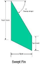
A 2019 study by Ayşenur Pektaş, et al. examines the effect of varying the sizing parameters of four frequently used and distinct fin shapes and their effect on the apogee and stability of model rockets. The study finds that certain components of a fin’s dimensions like span length and thickness consistently impact the apogee for all four types. For swept fins, the sweep angle as shown in Figure 1 measured from the horizontal directly affects its apogee (Pektaş, et al., 2019). The study uses a simulated model rocket designed to lift an 8kg payload to an altitude of 7km, which means that the data obtained about the performance of the four different types of rocket fin shapes does not necessarily apply in the same capacity to a smaller, more common model rocket. This is due to a variety of factors capable of affecting the results including the potential for substantial differences in atmospheric conditions during its flight, such as the significant differences in air density associated with a significant change in altitude. This would substantially affect the magnitude of the drag force acting upon the rocket during different parts of its flight and, thus, the applicability of the findings of the study to a smaller, less powerful rocket.
A common fallibility across the vast majority of studies in this field including those evaluated in this report is that hypotheses aren’t tested practically through the actual launch of model rockets. Data is instead obtained through use of appropriate modelling software so as to maintain the consistency and the reliability of data. However, this is not necessarily an indication of actual performance in real-life applications as atmospheric conditions are complex and rarely ideal and, as such, may only provide a generalised snapshot of a model rocket’s performance. This creates a serious disconnect between the current research and the actual real-word effects on a model rocket. This is because data is produced under a set of mathematical assumptions which are incapable of predicting the effects of minor, localised and spontaneous disparities in various factors.
Further research into this area of study is important because there are still serious inefficiencies when using rockets. The effects of this are observed most prominently in use of commercial rockets, especially in regards to getting substantial payloads into orbit. As model rockets serve as a scaled-down version, they allow for a substantially cheaper method of testing possible improvements which may be applicable to their commercial counterparts. It can also improve the fuel efficiency of model rockets when launched casually or as part of a competition, as the same mass of fuel can produce a comparatively larger apogee. These advances would potentially result in renewed interest in the field and pave the way to further scientific advancement and space exploration.
Scientific research question
To what extent does variations in sweep angle of a model rocket’s swept fins affect its apogee?
Aim
To determine the effect that the sweep angle of a model rocket’s swept fin has on its apogee.
Null Hypothesis
An increase in the sweep angle of a model rocket’s swept fins will not increase its apogee.
Scientific hypothesis
An increase in the sweep angle of a model rocket swept fins will increase its apogee.
Methodology
The experiment comprises of two primary methods of data collection, namely a practical and a simulated set of model rocket launches from which relevant data concerning the apogee is recorded. Average windspeed is monitored through accessing publicly available windspeed data recorded by a local airport at ten minute intervals throughout the launch.
The practical data set is produced using a clinometer and an altimeter to determine the apogee with the intention of using this to support the simulated data set, produced via Open Rocket software. This is because there is inherent uncertainty within the practically obtained results based on the role of other factors like windspeed that can be accounted for and monitored, but not controlled. In addition to this, there is the potential for slight inconsistencies in controlled variables which is beyond the scope of this investigation to fully account for, and the effects of this uncertainty are exacerbated by the limited size and extent of the practical data set due to time and cost restraints. However, these minor uncertainties are not implicit within the simulated data set which makes it a more reliable and accurate source by comparison, though the mathematical models that drive it fail to take such minor inconsistencies into consideration rather than account for them. As such, it acts as a theoretical prediction of the ideal apogee of a model rocket with fins of varying sweep angles and is also capable of producing a larger, more extensive data set to better observe trends in the data.
Although the practically-obtained data has inherent uncertainties that affect its reliability and accuracy, it is a vital part of the experiment as there will always be inherent uncertainties present in real world applications of model rocketry as factors like atmospheric conditions will rarely be ideal. This means that the simulated data cannot fully represent the effect of sweep angle of a model rocket’s fins on its apogee and, as such, the two data sets are necessary to gain greater insight into the extent of the proposed correlation between the dependent and independent variables.
Variables
In this experiment, the independent variable is the sweep angle of a model rocket’s swept fins, measured from the horizontal as shown in Figure 1 (page 3). This consequently impacts the total weight of the model rocket and the drag force acting on it during its flight. These subsequently affect the apogee of the model rocket, the dependent variable in the experiment. Most other factors like type
and brand of rocket engine and the surface area and mass of the base model rocket (excluding the fins) are controlled and kept constant so as to ensure that the experiment is valid and capable of producing highly accurate data. Other factors like wind speed are not able to be controlled, only recorded and accounted for in the results.
Equipment List
Equipment List – Fin Construction
1 x Sheet of pine plywood (1200mm x 810mm x 3mm)
1 x Pencil/pen
1 x 30cm Ruler (accurate to nearest mm)
1 x Engineers’ square
Power tools as required – Band saw, miter saw, jigsaw, disc sander
1 x Handheld clamp
1 x 10cm x 10cm square of 200 grit sandpaper
1 x Electronic balance/scales
Equipment list – Launch
24 x Estes B6-4 motors
24 x Estes pink B6-4 launch pins
24 x Starters
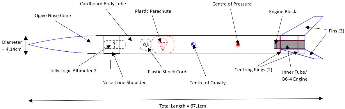
1 x Pre-made, custom built rocket body designed for B6-4 motors (see Figure 2 on page 6)
144 x Recovery wadding sheets
1 x Estes Porta-Pad II Launch Pad
1 x Estes Electron Beam Launch Controller
2 x AA Batteries
1 x Jolly Logic Altimeter 2
1 x Estes Mini AltiTrak Altitude Tracker (clinometer)
1 x Zap-A-Gap super glue
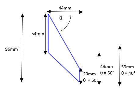
3 sets of 3 model rocket fins with sweep angles of 60°, 50°, and 40° (exact dimensions below in Figure 3)
1 x Camera
1 x Tripod
The general design of the custom built model rocket is shown below in Figure 2
The design and measurements of the swept fins are shown below in Figure 3.
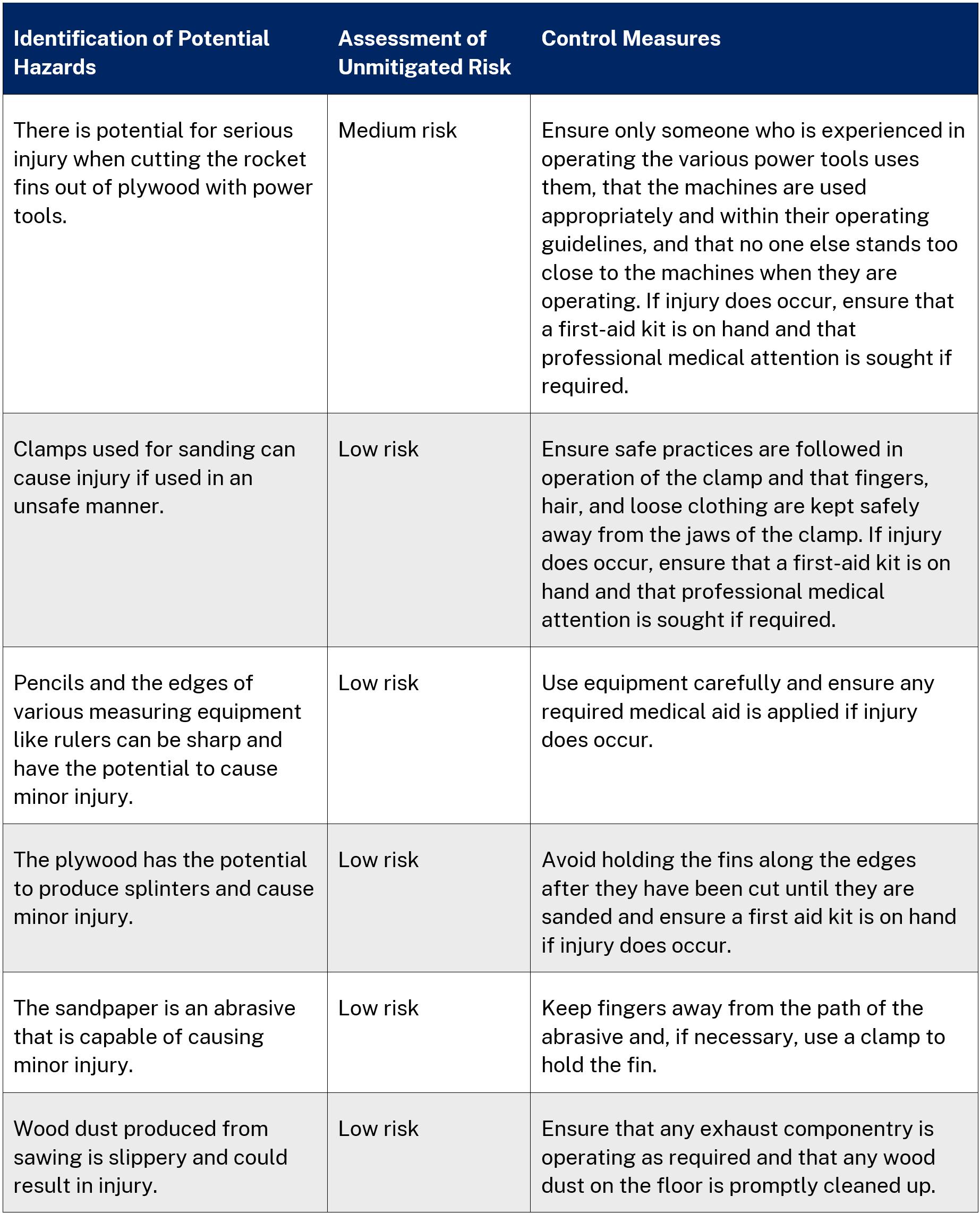
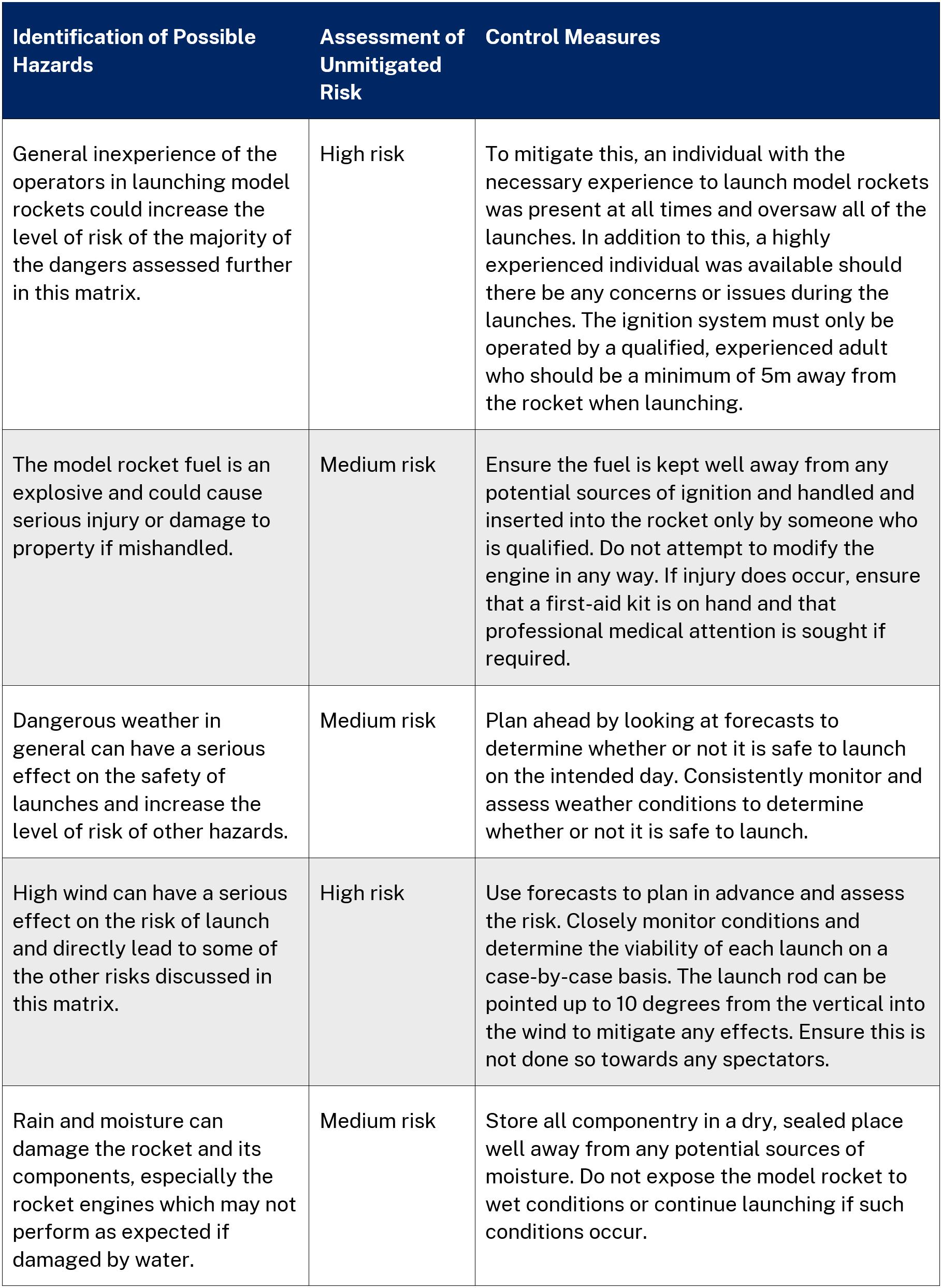
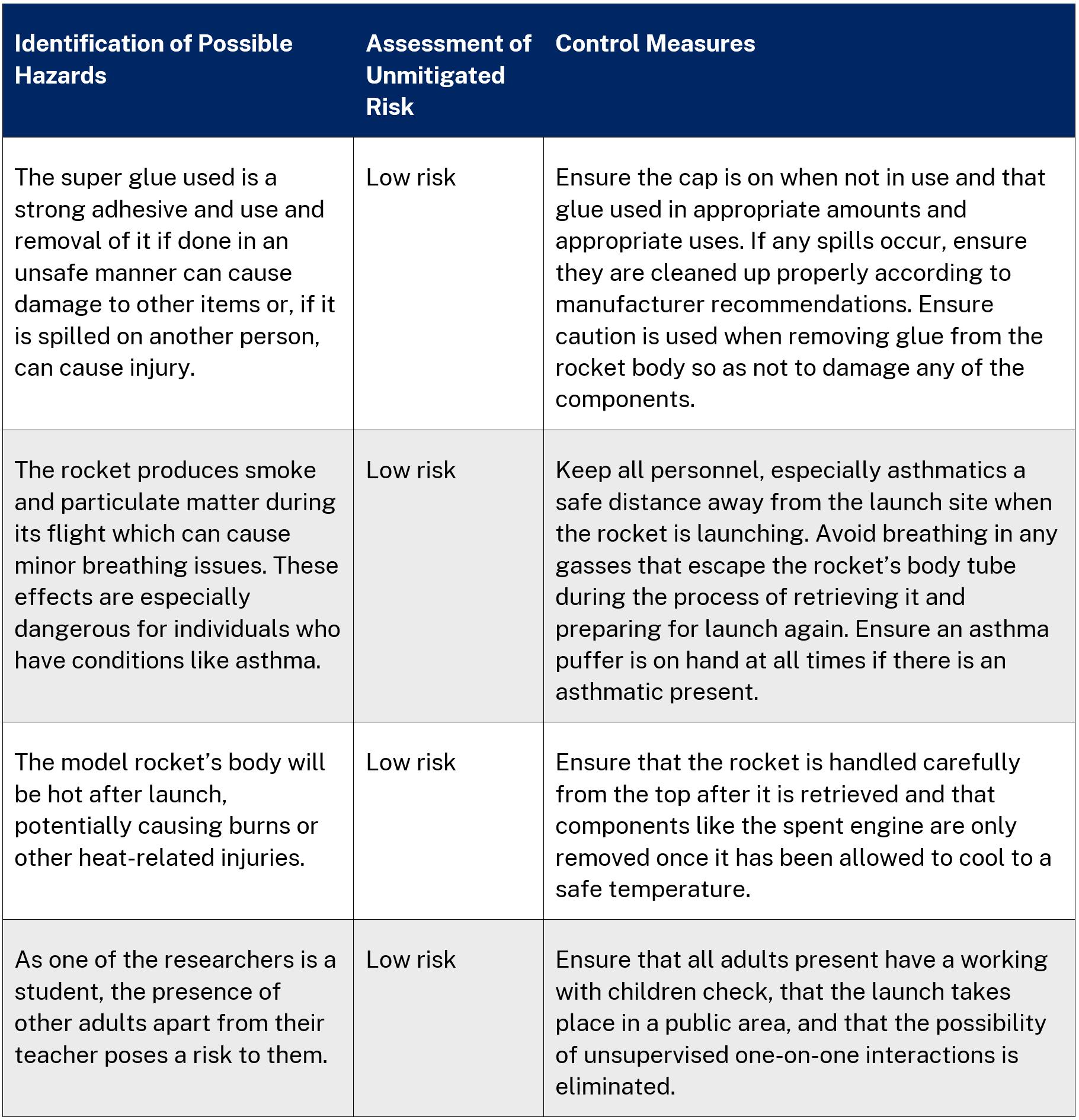
Risk assessment

Method for Fin Construction
1. Have someone experienced with using power tools use a band saw to cut a 44mm wide strip of plywood. This is to ensure precision of the span of the fins, accurate at least to the nearest mm.
2. Use a ruler, an engineers’ square, and either a pencil or a pen to mark out nine 96mm length rectangles on the strip of plywood, leaving a gap of approximately 5mm between each consecutive rectangle to ensure that there is ample room for error when cutting to ensure each fin has the right dimensions.
3. Clearly mark out the trailing edge of the 54mm long root cord measured from an upper corner of the rectangle for each fin. Using the ruler, draw a line from the marked, lowest edge of the root chord to the opposite, lower corner of the rectangle for all.
4. Mark out the length of the tip chord (60° sweep angle – 20mm, 50° – 44mm, 40° – 59mm) from that same opposite, lower corner of the rectangle, ensuring that three fins each have the same tip chord length. Ruler a line from the uppermost edge of the tip chord to the opposite, upper corner.
5. Use the miter saw to cut out each of the rectangles, ensuring the plywood is positioned so the saw blade will cut through the 5mm excess.
6. Use the jigsaw to cut along the leading and trailing edges of the fins, being sure to leave approximately a mm in excess to minimise the effects of any errors.
7. Clamp all of the fins together with the handheld clamp, lined up along their common edges, namely the trailing edge, and the root and tip chords. This is to ensure the dimensions of the fins will be as even and exact as possible.
8. Use a disc sander to accurately sand those common edges of the fins precisely down to their marked lines, adjusting the position of the handheld clamp as required in order to do so.
9. For the leading edge of the fins, separate the fins into three groups based on their sweep angle and sand each group down with the disc sander individually.
10. Lightly sand down any rough edges of the fins with the sandpaper to finish.
Method for Practical Model Rocket Launches
1. Carefully administer a line of super glue along the root chord of a given rocket fin, ensuring the glue is spread evenly along the whole edge. Press the root chord firmly and securely against the bottom of the rocket body for approximately five minutes or until the glue is fully set. Perpendicular
2. Repeat Step 1 another two times for the other two fins, checking they are all situated approximately 120° from each other.
3. Untangle the strings of the parachute then fold the parachute in half and lay it flat on the ground. Fold up the parachute by folding the two outermost quarters of the parachute into the centre. Repeat this an additional three times for the new outermost quarters. Fold the parachute in half over the centre then half again. Wrap the strings around the parachute to keep it folded.
4. Loosely pack 6 sheets of recovery wadding into the rocket body. Use a narrow pole to assist in this if required.
5. Place the parachute inside the rocket body along with the shock chord and the digital altimeter, ensuring each is securely attached to the nose cone. Place the nose cone onto the rocket body, ensuring it is reasonably loose.
6. Safely remove and discard any spent engines already in the engine block. Take a new engine and insert the starter tip as far as it will go into the side of the engine that has a small hole, the exhaust funnel. Put the pin firmly into the end to hold the starter in place. Insert the new engine into the engine block, ensuring the other wires poke out away.
7. Lower the rocket onto the launch pad, ensuring the rocket is attached to the metal launch rod via the launch lugs. Attach the launch controller’s starter clips to the two wires of the starter, making certain that neither the two wires nor any part of the two clips end up touching, else the rocket will fail to launch.
8. Check that the launch rod is pointing into the wind so as to minimise the effect of the wind which could push the rocket far away, where it could be difficult to retrieve it from.
9. Confirm all personnel are safely clear of the launch pad before pressing the pin into its place in the controller until a red light appears. Press the button to launch the rocket.
10. During the model rocket’s flight, have someone stand a safe, known distance away (for this experiment 60m was sufficient) from the launch pad to use the manual Estes Altitude Tracker, sighting along and lining up the two ridges with the rocket. Upon observing the rocket reach its apogee, press on the clinometer’s gravity protractor to measure the angle of inclination. Record the results.
11. Retrieve the model rocket from where it lands. Record the results off of the digital altimeter then reset it.
12. Repeat Steps 3 – 11 another five times for that fin set.
13. Carefully break off the fins to swap them, ensuring that minimal damage is done to the fins and the rocket body.
14. Repeat Steps 1 – 13 a minimum of eighteen successful times, excluding any failed launches.
Results
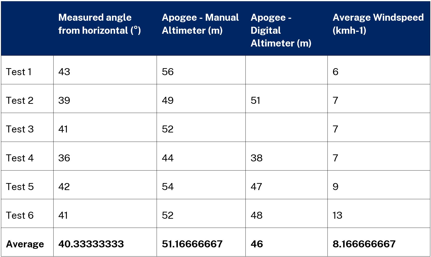

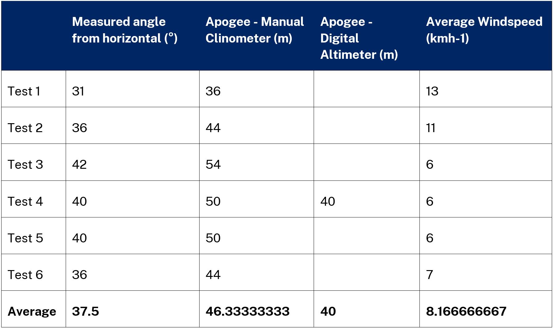
Note: any spaces in the digital altimeter column for Tables 1 – 3 are indicative of its failure to record an apogee for that test.
Discussion
In Tables 1 – 3, on pages 12 and 13 two sets of values for apogee were determined experimentally by two distinct pieces of equipment, one set by a manual clinometer and the other by a digital altimeter. Using both pieces of equipment was intended to be a fail-safe. Should the altimeter fail to record a value, the less reliable result calculated from the clinometer would suffice so useful data could be obtained from every successful launch. This method became particularly useful for Table 3 where five out of the six launches failed to produce a value on the digital altimeter.
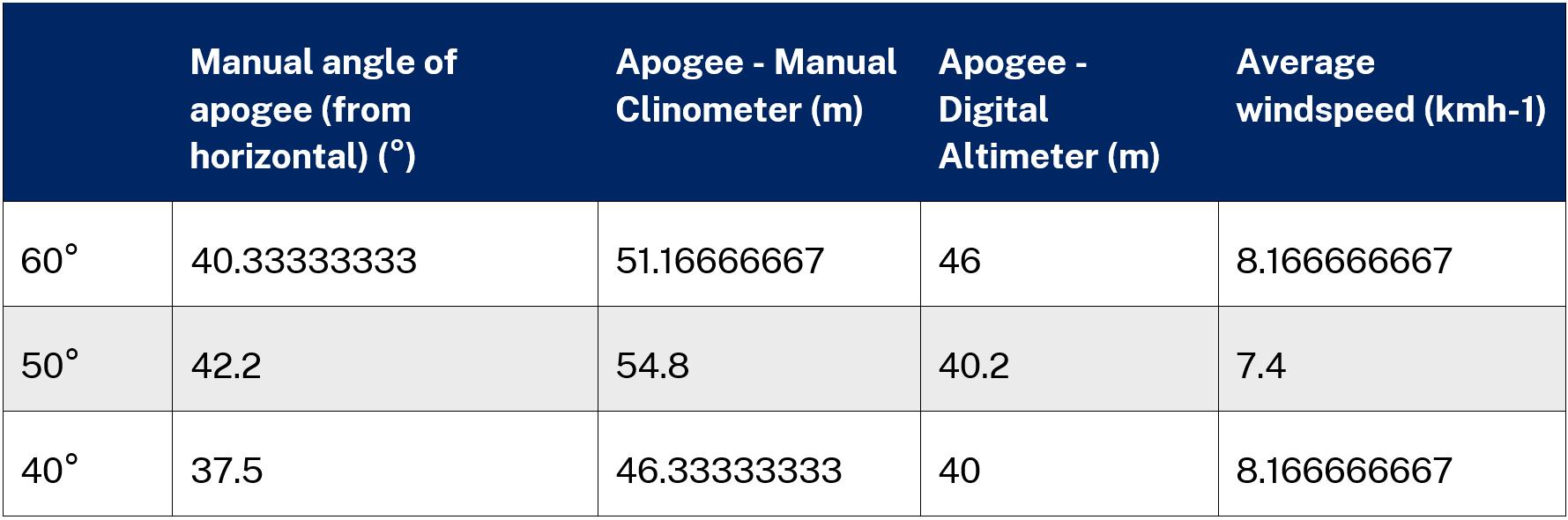
Table 4 on page 13 displays a direct comparison between the average practical results obtained. In particular, the apogees obtained by the clinometer are substantially higher in comparison with those produced by the altimeter, actually recording an increase in apogee between the 60° and 50° sweep angles where the digital altimeter records a decrease. This indicates that the clinometer is substantially less accurate and less reliable in comparison to the digital altimeter.
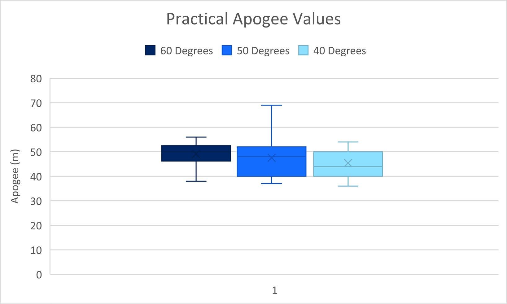
Figure 4 on page 14 demonstrates the unreliability inherently associated with the practical data as there were a large range of values obtained for the apogee for all fin types. This indicates that the reliability is relatively low. In addition to this, the interquartile ranges for all three sweep angles extend over very similar values despite the decrease in the median apogees, the latter trend being is supported by the other data.
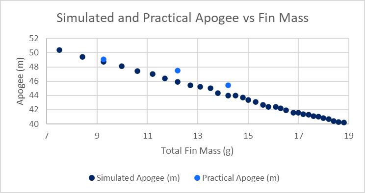
As a model rocket is acted upon by four distinct forces – weight, thrust, drag, and lift (Benson, 2021) – it can be inferred that changing the sweep angle of a model rocket’s fin will have an effect on the weight force acting of the rocket. This is supported through the graph of the simulated data, Figure 6, where it is clear that fin mass (the only source of variation of mass) and apogee are correlated. This is supported by a r value of0.999, which indicates the correlation is negative, an r2 value of 0.9979 which indicates that there is a strong correlation, and a pvalue of < 0.0001 which indicates that the correlation is statistically significant. Therefore it is evident that weight force as influenced by a change in sweep angle has a significant effect on apogee, meaning that an increase in sweep angle produces a decrease in mass, and a resultant increase in apogee.
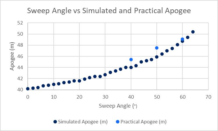
However, this does not fully explain Figure 5, which follows an exponential trend, indicating that a change in sweep angle of a model rocket’s fin is not affected solely by its mass. This cannot be a result of a change in thrust as the type of rocket motor, the source of thrust, were consistent across all trials, meaning that thrust does not account for the differences in Figure 5. Given that the lift and drag forces are both beyond the scope of this investigation to quantify, their influence can only be inferred. Lift and drag are both forces exerted on an object by a fluid flowing around it, acting based on the difference in relative velocity between the rocket and the fluid it passes through. Drag opposes the motion while lift acts perpendicular to it (Benson, 2021). As sweep angle increases, there is a smaller area on which friction can occur and the pressure exerted by the air on the fins in also reduced, thus substantially reducing drag (Benson, 2021). This in conjunction with the change in weight force accounts for the exponential increase in apogee with sweep angle. This is supported by statistical analysis, where the effect of sweep angle on simulated apogee was found to have an r value of 0.9673 indicating a positive correlation, an r2 value of 0.9356 which indicates that there is a strong correlation, and a one-tailed p-value of < 0.0001 which indicates that the correlation is statistically significant.
Although the r and r2 values determined to support the trends in Figure 5 are useful and accurate for the dataset, they only represent a linear regression. If applied over a greater data set, this would become an increasingly inaccurate representation as the curve would become progressively more prominent. In light of this, more specialised forms of statistical analysis that can account for an exponential trend should be used for more extensive datasets or for tests where drag becomes a more influential factor. Despite this issue, the curve displayed in Figure 5 is still weak enough that linear regression can still be used as an accurate representation of the statistical significance of the correlation between the sweep angle and the apogee of a model rocket.
In regards with the fin construction, there is serious issues with the validity of the methodology to produce the swept fins. This is because the fins were measured, cut, and sanded to the nearest mm even though values for components like the length of the tip chord were actually irrational numbers produced by trigonometric ratios. As such, the practically tested sweep angles were very close to the intended angles, but not exact. This along with the substantial potential for error in the actual production of the fins indicates that the dimensions entered into Open Rocket for the simulations are not precisely met by the actual fins. To mitigate the errors in manually cutting the fins as well as to significantly improve the number of decimal places of accuracy that can be cut to, a laser cutter can be used to ensure a greater degree of accuracy. This allows for more decimal places to be reached and the resultant angle closer to the intended angles.
Both the accuracy and the reliability of the practically obtained values of apogee are low as apogee was only measured by the altimeter to the nearest metre, indicating that the actual values recorded could, in actuality, be ± 0.5m. This is a substantial margin of error for apogee values that, based off the simulated data in Figure 5, could be expected to vary by just two metres between practically tested angles in some instances. To mitigate this, a more powerful rocket could be used so any change in sweep angle is more substantial and an uncertainty of ± 0.5m is less significant.
The practically obtained data has a high degree of uncertainty inherent within it, primarily relating to the differences in atmospheric conditions occurring between and during launches that for the most part cannot be meaningfully measured nor accounted for. This was mitigated in part by obtaining publicly available windspeed data from a local airport, however since the launch site was a number of kilometres away from where that data was collected and differences in geographical terrain could have influenced the viability of that data in applying to the launch site, the windspeed data serves as little more than a generalised, likely inaccurate approximation. Additionally, as the launches were conducted over a number of hours, changes in temperature throughout the time period would have affected the air density and, consequently, the drag acting on the model rocket. As the launch site was in full sunlight, even the motion of scattered, isolated clouds blocking the sun could have affected the apogee of the model rocket and, as such, consequently inhibited the usefulness of the practically obtained data. However, it is shown in Figure 5 that there is still a difference of as much as two metres between the theoretical and practically obtained apogees. Additionally, it is assumed that the fins are solidly attached to the rocket, that they are evenly placed 120° to each other and that there is no independent motion of the fins relative to the rocket or, indeed, that none of the components of the model rocket move independently to each other.
Further and more diversified testing is necessary in this field of research to improve the efficiency of rockets, in particular through model rockets. One of the most prominent directions of this field of research would be to use a fin that has an airfoil cross-section to examine the influence of lift on apogee. The recent advancement of grid fins, a type of fin that is most well-known from SpaceX’s application of them, could also be applied to a model rocket. More complex geometric shapes like curves could also be used in comparison to more traditional triangular or quadrilateral shapes to assess which is more effective in reducing drag forces.
Conclusion
With 95% confidence level and a corresponding one-tailed p-value of < 0.0001, it is evident that there is a statistically significant correlation between the sweep angle of a model rocket’s fins and its apogee. This is further supported by an r2 value of 0.9358, which indicates an extremely high linear correlation between the two variables. As such, it is clear that increasing the sweep angle of a model rocket’s swept fins does increase the apogee, thus providing sufficient grounds to reject the null hypothesis and accept the scientific hypothesis. As an increase in sweep angle also decreases a model rocket’s mass which in turn increases apogee, a comparison of mass and apogee has been used to support these findings. This is evidenced through an r value of 0.999, an r2 value of 0.9979 and a p-value of < 0.0001 which also indicates an extremely high correlation between the variables.
Acknowledgements
I would like to thank my Extension Science teacher, Erika Savage, for providing feedback in refining my ideas and in her supervision and assistance with the launches, in addition to my mentor, Matt Dodds, who provided equipment and lent his expertise and advice on the launch method. I would also like to express my gratitude towards Rodney New who helped in cutting out and sanding the rocket fins, as well as my parents, Russell Davies and Ailsa Davies, for their role in data collection and recording of the launches. I would also like to thank Amy Johnson, Michael Kellner, Byron Smith, and Brian Shumack for their advice on how to further polish my ideas.