
56 minute read
5.4 Specification of the entities


5.4 Specification of the entities
In the following tabs specifications about classes, relationships and properties are provided.
•
below and next pages
Tab. 4
Specification of entities, relations and properties in the space ontology
1. OWL Class
Entity definition WORKSPACE
A workspace represents a physical entity within the construction site. It can be used for various purposes according to the proposed sub-classes. The list of properties and motivations for their computation within the system are listed in the tabs.
hasID: type: name assignment
hasCapacityDimension: type: real number assignment
Datatype Properties:
hasDimension: type: real number assignment Indicates the dimension of the footprint area of a rectangular prism that acceptably approximates the workspace. hasSmallestUnit type: real number assignment If the workspace is divisible, this property indicates the dimension of its smallest units. For example, some construction objects such as material are in packages, boxes or other units. When being located on site, they can be located in separated units if occur. The dimension of the smallest unit is needed to decide the size of split location. Object such as equipment are rigid in size and this aspect is reflected in the flexibility property hasHeight: type: real number assignment Includes the highest point of the space hasCentroid (X-Y axis): type: real number assignment Indicates coordinates of geometric centroid of footprint hasLocation (X-Y axis): type: real number assignment Indicates coordinates of workspace location after that the site simulation is carried out and its optimal allocation is defined hasMobility: type: boolean assignment (YES/NO) Indicate if the object is mobile or stationary hasMovability: type: boolean assignment (YES/NO) Indicates if it is acceptable to change the location of object during the project hasContainability: type: boolean assignment (YES/NO) Indicates if the object can be used later to contain another object hasFexibility: type: string assignment Indicated the flexibility of object’s shape (flexible/sizable/rigid) hasOrientation: type: real number assignment The angle by which the object is rotated when located on site referred to its reference construction product hasPotenzialHazard: type: real number assignment A value which represents a rough quantification of safety hazards related to the activity whose workspaces are simulated
Object Properties:
imposes:
Properties
Domain: Workspace Range: Constraint
FU
hasTopologicalInteraction:
Domain: Workspace Range: Workspace
TR
Define the interconnectivity level among two workspaces using a set of standardized values.
hasInteractionValue:
Domain: Workspace Range: Workspace
The Interaction Value defines the proximity level which occurs between two workspace in a range scale from 0 to 10. isRequiredBy: Domain: MicroSpace Range: Activity FU-TR
isRequiredBy:
Domain: MacroSpace Range: Phase
FU-TR
Follow the list of subclasses that describe all kinds of workspaces considered by the proposed ontological model.
1.1 Sub-Class Macro WorkSpace
Entity Definition: spaces located across sites in terms of site-layout requirements. Phases require Macro-Level workspaces, Activities require Micro-Level Workspaces.
1.1.1 Sub-Class StorageArea
Entity Definition: The area required to keep material or tools for the time between they are delivered to site to the their use.
1.1.2 Sub-Class GenericArea
Entity Definition: Whatever area which is required for the site layout organization to ensure Phase progress.
1.2 Sub-Class Micro WorkSpace
Entity Definition: workspaces required by an activity which are located within the proximity of the components (construction products) being installed.
1.2.1 Sub-Class LaborCrew Space
Entity Definition: represents the space required by the labor crew installing the construction product
generates:
Domain: LaborCrew Space Range: Hazard Space
1.2.2 Sub-Class Equipment Space
Entity Definition: represents the space required by the equipment supporting either the Construction Product or the labor crews.
generates:
1.2.3 Sub-Class
Domain: LaborCrew Space Range: Hazard Space
Hazard Space TR
Entity Definition: represents a hazard space generated by a Labor Crew space or Equipment space
1.2.4 Sub-Class Protected Space
Entity Definition: Represents the space required to protect the construction product for a given time interval.
1.2.5 Sub-Class Safety Space
Entity Definition: Represents a tolerance (safety distance) between two workspaces to prevent safety hazards such as collision between two spaces or a tolerance space from objects falling from height.
1.3 Sub-Class Bound Space
Entity Definition: A bound space is a physical entity which represent the site boundary and objects that reside on site before the commencement of construction and hence have a known location on site. For examples Bound Spaces could comprise trees, existing buildings, marked areas on site such as unavailable, unsafe areas, life lines. They occupy space on site and their space is deduced from the total site land. Their Topological Interaction with other workspaces is disjoint and their Interaction Value with other workspaces is 0, the smallest.
In the figure below is printed the visualization of the ontology computation with all the aforementioned properties as extracted from the ontology editor Protégé by using the VOWL visualization functionalities.
•
5.7 Space Ontology implementation in the modeling environment (Snippet from the Ontology Modeling Environment Protégé)

•
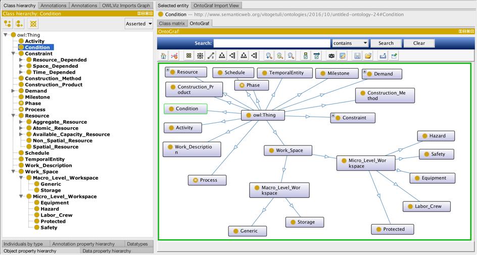
5.8 Space ontology edited in Protégé and visualized with VOWL notations (Lohmann, 2014) in a forcedirected layout. The graphical representation of OWL entities is made of visual elements. Blue circles represent classes and sub-classes; blue rectangles represent property labels of relations, the ones with no border represent datatypes, and green rectangles represents the property label of data-types (Snippet from Protégé)
chapter 6
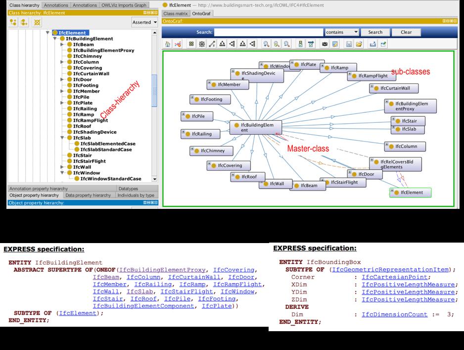
A Building Information Model (BIM) is provided with a standardized interface for data exchange which is nowadays widely accepted in AEC Industry: the so-called IFC (Industry Foundation Classes) standard. The IFC serves as a basis for the exchange of building model data where building components are expressed in terms of objects with attributes. The proposed approach aims to make use of this information in order to link the knowledge base to the IFC-data schema. To achieve this goal different methods have been proposed in literature with the common approach to extract and reuse building data (Dhillon et al., 2014). Unlike in these methods, the presented approach tries to merge entities and relations required for the space scheduling purposes as included in the IFC. This would be desirable in order to define an ontology-based common data structure that is at once completely integrated with the other previously presented modeling domains (scheduling and space ontologies). This is achieved by using the ifcOWL ontology (Buildingsmart, 2014) which is precisely meant to allow extensions towards other structured data sets made available using semantic web technologies such as the one used in our system (OWL language). Since the ifcOWL ontology is quite complex because of the huge number of classes and properties it contains (Figure 6-1), an in-depth study has been carried out in order to filter only the required entities for achieving our construction planning purposes.
This approach produced a reduced ontology, here called ‘Construction Product Ontology’, for the description of the building structure in the proposed system together with the required building objects information. In the next paragraph is presented the sub-ontology after a brief exploration of the IFC structure.
6.1 IFC-based Building Model exploration
Industry Foundation Classes (IFC) represents an object-oriented format which provides a universal base for data exchange in building lifecycle. It has been developed by the
•
6.1 Ontology metrics of IFC-schema visualized within the ontology editing environment (Snippet from Protégé)

International Alliance for Interoperability (IAI) on the basis of EXPRESS language as a part of the STEP standard [ISO 103030] for the product data exchange. The schema of IFC is quite complex. Concerning the scope of this work, in order to represent just an IFC building model, it is essential to show only the objects needed to formulate the construction planning domain. The IFC building model is represented with a hierarchical spatial structure to organize a building project which is comprised in a so-called IfcProject. First element within the structure is included in the class of IfcSite which defines the area of land on which the project construction will be completed. A building (IfcBuilding) in IFC may have one or multiple stories (IfcBuildingStorey). Each building storey may have zero or multiple storeys. Each building storey may have assigned zero or more spaces with certain functions (IfcSpace) related to it -i.e., a building structure which has only one wall is a building with zero spaces-. For example, rooms in IFC are represented by the IfcSpaces class with a predefined PropertySet. Building elements and opening elements are represented as subtypes of spatial structure elements (IfcSpatialStructureElement). Each building element (IfcBuildingElement) has zero or more opening elements (IfcOpeningElement) i.e., a wall without any door or window has zero openings, whereas each opening element (like door, window) is attached to only one building element. IfcSpatialStructureElement links between building elements and upper structure of building (project, site, building, storey and space) as it defines spatial structure of a building and its parts.
Each IfcProduct, that is an abstract representation of any object that relates to a geometric or spatial context, is located in IfcGrid which is a planar design grid defined in 3D space used as an aid in locating structural and design elements. The position of the grid (ObjectPlacement) is defined by a 3D coordinate system. The relative placement of a product in relation to the placement of another product or the absolute placement of a product within the geometric representation context of the project is defined by the class IfcLocalPlacement. The particular geometric representation of a product is defined by IfcShapeRepresentation which includes several RepresentationIdentifier. It is derived from refers to geographic locations (IfcLocalPlacement) of building elements and their geometries. Geometric representation in IFC is built on solid geometries.
6.2 Topological structure
The entities and properties that have been selected are able to define a link between a given application, that may work on the construction planning domain by using the proposed Knowledge, and a BIM IFC-based, and are listed and graphically depicted below (Figure 6.4). Moreover, the main topological relations with the other sub-ontologies are specified. a. IfcBuildingElement. This abstract class, that works as super-type, comprises all elements that are primarily part of the construction of a building, i.e., its structural and space separating system. Sub-types are IfcBeam, IfcColumn, IfcCurtainWall, and so forth. The classes included in the knowledge base of the presented system architecture are graphically represented in (Figure 7-3). They are defined as sub-classes of the master-class ConstructionProduct. In this way, for each of them a different ConstructionMethod will be defined and, in turn, will consist of a number of individuals grouped within classes (i.e., Labor-
Crew-Space, Protected-Space, Equipment-Space, etc.) and properties, as described in the
Construction Space Ontology. By doing so, each building objects composing the given
BIM, will be allocated to a specific construction method via the transitive relation isProducedBy. b.Then, within the IFC-based data structure, each element is specified by using a number of capabilities, mainly through property sets (e.g., Material, classification, documentation, boundary, coverings, etc.). For our scheduling purpose, in order to provide the system with information able to support the rule-engine in the automatic generation of the structural construction sequence, the objectified relationship IfcRelConnectsElements has been selected. It handles the connectivity between elements with a 1 to 1 relationship. The connectivity may be related to the shape representation of the connected entities by providing a connection geometry or a point connection with attributes with assigned values on X, Y
•
6.2 Typologies of building objects considered in the System as imported from the IFC structure (Snippet from Protégé)
and Z-axis. If such a relation exists between two building objects, making a comparison between the height attribute on Z-axis, a rule-engine -which works by using such ontologies- could establish a time relation IntervalBefore between the items with a higher
Z-value and the other one, automating the generation of a structural sequence. c. Furthermore, for spatial planning purposes, a reduced BIM, which includes space availability in site -building objects and workspaces- should be generated in order to: • simplify the representation of the geometries of building elements and • find the optimal workspaces allocation in respect to the location of the building elements to which they are related. Therefore, every IfcBuildingElement will be represented in the proposed space ontology as a bounding box, which shows the maximum extent of the body within the coordinated system established by the attributes of the IfcLocalPlacement class. The bounding box representation is the simplest geometric representation available. It is defined by a Corner, as three-dimensional Cartesian point, along with three oriented length measures defining the X, Y and Z values of the box as depicted in point (2) and (5) of Figure 6.3.

•
6.3 Selected entities and properties in the ifcOWL ontology to link scheduling and space ontology to a BIM Model IFC-based
6.3 Introduction of BIM data in the KB
In specifying the Knowledge-Base, two sources of information are considered: building data from a given BIM according to aforementioned specifications, and user’s experience. Their integration in the knowledge base by means of ontologies –OWL individuals-, has been designed as later specified and graphically represented in the figure below (Figure 6.4). 1. The configuration process starts having a Building Information Model to be processed, whatever the Level of Development (LOD) is made. 2. The given BIM, with parsing IFC schema defined in EXPRESS format (ISO 1030311:20041)1, is converted in OWL format (later called ifcOWL*). Doing so, the expert system is provided with BIM in an ontological structure (classes, relations, properties, individuals). 3. The ifcOWL* is merged with our ‘construction scheduling ontology’ so that only the needed ontological components are captured (i.e., geometry information of building objects with their bounding boxes and local placements, structural connections among objects). This process is carried out by using a functionality of the editing environment Protégé. In this way OWL-individuals are generated using BIM project information. 4. The user, at this point, can add individuals to the ontology structure in terms of construction methods (see Scheduling Ontology in Chapter 4) and their workspaces with their related property sets (see Space Ontology in Chapter 5). It should be noted that, at the beginning of the configuration process, the ‘construction process ontology’ works as a neutral model which contains no specific object but only abstract entities. 5. At this point, the reasoner updates the ontology, the Knowledge base is uniquely populated with specific individuals and is ready to support reasoning mechanisms.
1 ISO 10303 specifies a language by which aspects of product data can be defined. The language is called EXPRESS. ISO 10303-11:2004 also specifies a graphical representation for a subset of the constructs in the EXPRESS language. This graphical representation is called EXPRESS-G. EXPRESS is a data specification language as defined in ISO 10303-1. It consists of language elements that allow an unambiguous data definition and specification of constraints on the data defined.

•
6.4. Designed information-flow implemented to introduce BIM data (as filtered according to the Product ontology) and user experience within the Knowledge-Base
chapter 7
The representation of temporal relationships and temporal properties in the proposed model is fundamental considering that a schedule describes the construction process across time. In this regard, we are concerned with the exploration of temporal relationships between ontological entities. Therefore, we will adopt a discrete, linearly-ordered time domain, and we will focus on absolute time. The specific time relations we are interested in are those of Allen’s interval algebra (Allen and Ferguson, 1997). Time dimension is incorporated into the model by associating time intervals to relationships between entities. Finally, the time ontology presented in (Cox and Little, 2016) have been chosen after reviewing the most used by other authors and customized for our purposes. In the following paragraph its structure is presented.
7.1 Topological temporal entities
Four key points have driven the modelling of the time variable in the knowledge-base with the aim to manage the time progression of entities in site and the translation of spatial constraints (e.g., workspaces conflict, etc.) into temporal constraints (time interval between conflicted entities) to be imposed into the schedule generation: i. Temporal Relations between entities included in the other sub-ontologies; ii. Representation of time positions; iii. Duration of construction intervals; iv. Temporal Reference System of the Expert System. By doing so, unlike traditional Gantt Chart and network diagrams, temporal relationships with properties can be established between two entities and, moreover, each entity can be linked to more than one entity at the same time and with different relationships types. Therefore, with reference to (i), the TIME ONTOLOGY is based on binary relations on intervals in order to represent the temporal information on which a schedule may be structured and on which the problem of automatic reasoning can rely. This is carried out in the ontology by using the class TemporalEntity which has object-properties able to assign temporal
instants to the individuals (e.g., building objects, workspaces, etc.) for the definition of their beginning and end (i.e. hasBeginning and hasEnd). This class defines the time properties of each Activity which, in turn, is related with other classes, i.e., Resources and Workspaces via the relationships handles and requires respectively. Such a network allows the ontology to automatically assign the same temporal interval of an Activity to the Resources and Workspaces which handle the Activity itself when a time interval has been assigned to only one of them. This is achieved assigning the transitive property to the object-properties hasBeginning and hasEnd. Interval and Instant are two subclasses of TemporalEntity. This specification allows the system to mark a distinction between a Milestone and an Activity in the Schedule, in fact: a Milestone is an Instant -that can be seen as an interval with zero length- while an Activity is an Interval having an actual duration. The object-property isA is used to define these logical connections. ProperInterval is a subclass of Interval and is used to define possible binary connections between two intervals (i.e. intervalMeets, intervalOverlaps, intervalBefore, intervalDuring etc.), and therefore between to Activities and their related classes, (e.g., resources and workspaces). In this respect, the interested relations are those of (Allen and Ferguson, 1997). Such classes are the most important for the construction schedule generation because they provide the rule-engine (see the following chapter) with the new relations that have to be established between all those entities included in the ‘conflicts checking process’. With reference to (ii), three classes describe the temporal position within a reference system and they all have an object property hasTRS to indicate the Temporal Reference System (TRS). TimePosition has properties to describe the position using both a number (i.e. a temporal coordinate), or a nominal value. With reference to (iii), the duration of an interval can have different descriptions: class Duration describe the duration as a number. GeneralDurationDescription has different properties to specify a duration (e.g. hours, days, months, etc.) and DurationDescription fixes the temporal reference system used in the proposed ES to the Gregorian calendar. Specifications of classes with their interaction domains and range as computerized by using OWL language in Protégé are described below in Tab.5 and graphically depicted in Figure 7.1.
7.2 Specification of entities in the Time Ontology
Below, the structure of the Time Ontology (Cox and Little, 2016) which drives the OnSITEsimu in defining (1) temporal relations, (2) temporal reference systems, (2) time position with time unit and (4) interval duration is presented.
•
below and next page
Table 5
Specification of entities, relations and properties in the time ontology
T1. OWL Class
Entity definition:
Object Properties: TEMPORAL ENTITY
This Class define a temporal interval which is assigned to each Activity.
before:
If a temporal entity T1 is before another temporal entity T2, then the end of T1 is before the beginning of T2
after:
If a temporal entity T1 is after another temporal entity T2, then the beginning of T1 is after the end of T2
hasBeginning:
hasEnd:
hasDuration:
This object property fixs the duration of a Temporal Entity expressed as a nominal value
Properties
Domain: Temporal Entity Range: Temporal Entity
Domain: Temporal Entity Range: Temporal Entity
Domain: Temporal Entity Range: Instant Domain: Temporal Entity Range: Instant Domain: Temporal Entity Range: Duration
T2. OWL Class Entity definition:
Object Properties:
T3. OWL Class
Entity definition: INTERVAL
This class define a Temporal Entity with an extent or duration
inside:
Properties
Domain: Interval Range: Instant
INTERVAL RELATION
A Temporal Entity with a duration defined by using the class Interval which is supported by the seven interval relations listed below in object properties.
Object Properties:
T4. OWL Sub-class
intervalBefore:
intervalMeets:
intervalOverlaps:
intervalStarts:
intervalDuring:
intervalFinishes:
intervalEquals:
DATE TIME INTERVAL Properties
Domain and Range: ProperInterval Inverse Property: After
Domain and Range: ProperInterval Inverse Property: MetBy
Domain and Range: ProperInterval Inverse Property: OverlappedBy
Domain and Range: ProperInterval Inverse Property: StartedBy
Domain and Range: ProperInterval Inverse Property: Containts
Domain and Range: ProperInterval Inverse Property: FinishedBy
Domain and Range: ProperInterval Inverse Property: Equals
Entity definition:
Datatype Properties:
Object Properties:
This is a subclass of ProperInterval, defined using the multi-element DateTimeDescription
xsdDateTime:
hasDateTimeDuration:
Domain: DateTimeInterval Range: xsd:DateTime
Properties
Domain: DateTimeInterval Range: GeneralDateTimeDescription
T5. OWL Sub-class Entity definition:
Datatype Properties:
Object Properties: INSTANT
This is a subclass of TemporalEntity which define a TemporalEntity with zero duration
inXsdDateTime:
Position of an instant, expressed using xsd:DateTime
inTimePosition:
Domain: Instant Range: xsd:DateTime
Properties
Domain: Instant Range: TimePosition
inDateTime: Domain: Instant
Range:
GeneralDateTimeDescription


•
7.1 Time ontology edited in Protégé and visualized in a force-directed layout by means of made of visual elements. Blue circles represent the class hierarchy; blue rectangles represent relations, the green ones represent the property label of data-types, yellow rectangles represent the data assignment (Snippet from Protégé)
chapter 8
From the theory and application sections previously presented, it has emerged that construction planning and scheduling methodologies have known obstacles in their practical application mainly because of two facts: (a) the lack of interlinking between automated models, human planning, and digital building models (b) the lack of a standardized and codified knowledge Base able to support digital and automated construction planning processes. Moreover, the complexity to hold together factors at play in simulating and scheduling construction site activities and the complexity to grinding out a detailed construction process simulation often overwhelm solving capabilities of human planners even if they have deep knowledge which could provide decisive assistance to a hypothetical integrated system architecture. However, although the total automation is being mooted in most of domains, the aforementioned components should work in synergy, bringing problem-solving strength to the table joining forces to give expression to a unique system architecture. This is complicated by the facts that human planners do not reason about construction process plans at the level of workspaces as well as their temporal-space allocations because of the off-putting amount of time to model workspaces geometries and simulate all of them across time as well as their interaction. Even if in the proposed ontologies has been clearly emerged the need to represent workspaces as a key concept. In the light of these facts, this chapter represents the conclusion of the book in which it will be presented how ontologies could be able to support planning and scheduling processes. This is carried out presenting an Expert System Architecture supported by the presented ontologies developed by the author. Due to the object of this book only the architecture of the expert system is presented in order to clarify the importance to have available a computerized knowledge base to use to design reasoning mechanisms.
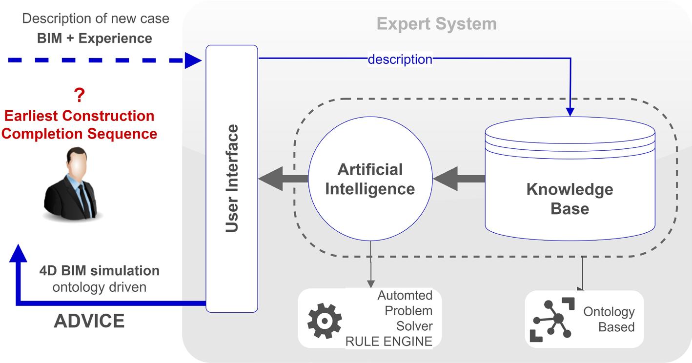
8.1 OnSITEsimu Expert System
OnSITEsimu is an expert system proposed in literature by the author which uses the ontologies presented in the previous chapters to works. In this book, which is strictly dedicated to
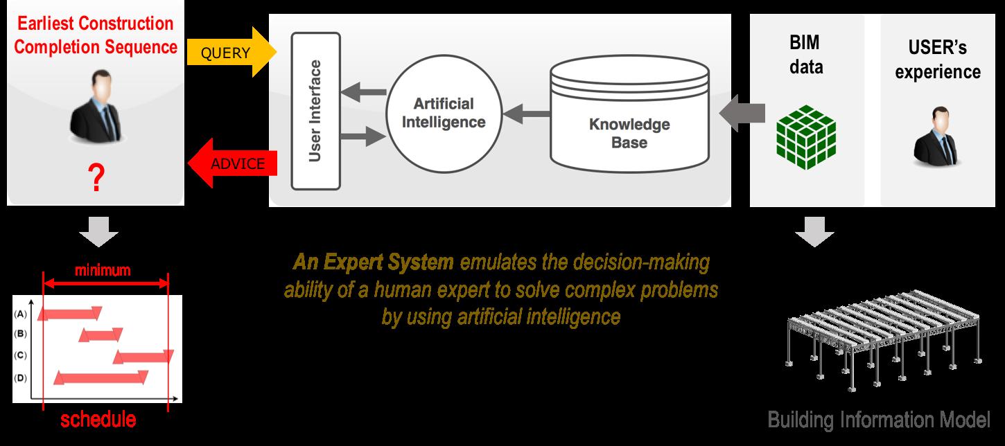
provide the reader with theory and applications of knowledge modelling and in particular of ontologies modelling, the architecture of such an expert system is presented in order to clarify how ontologies could be able to support automated reasoning processes. OnSITEsimu has been designed for computerizing a novel approach to the construction spatial scheduling (BIM-compliant) and to act as a human expert to solve the complex problem to identify the earliest construction sequence considering the temporal space allocation of resources in site. It could be considered as an intelligent workspaces planner and activities scheduler of the construction process. Its main characteristics can be expressed in terms of blocks it is composed of:
1. A knowledge base
The knowledge Base (KB) contains the domain-specific knowledge required to solve the problem. According to the goals, we consider the domain of building construction process focusing on site items, allocation and optimization of workspaces required to execute activities on site and their mutual relations as well as with the building objects.
Once, such a knowledge -construction site entities- is organized so that it will be ready for use for the knowledge representation. It involves the preparation of a knowledge map, by using a specific computational language, and its own encoding in the KB. For this purpose, it has been used ontologies for modelling and the OWL language (Web
Ontology Language) for computerizing –produce a script- such a KB and make it machine-readable. Just a KB alone is not of much use if there are no facilities for manipulating the knowledge to deduce something from the KB itself. This is carried out by the Inference Engine.
2. An inference engine
The Inference Engine (IE) carries out the reasoning whereby the expert system reaches a solution. The system is designed to automate the generation of the shortest schedule given a number of input data (e.g., information on building objects, construction methods, resources and workspaces dimensions, etc.). It utilizes a set of spatial heuristics and predefined rules to schedule the activities in a chronological manner.
To do this, the KB and information provided by both an user and a given Building Information Model have combined in order to infer new knowledge (i.e., the shortest possible total duration) by using a pre-designed rule-set.
3. A user interface
Generally, the user interface is the block where the user interacts with the expert system. In the proposed model, two main user interface have been identified:
•
8.1 OnSITEsimu: Expert System architecture
• the ontology-editing environment that works as repository of the KB where the user adds individuals within the conceptual knowledge the system is equipped with. Those individuals describe construction methods he has in mind to use for each type of building object the given BIM is composed of; • a Virtual Construction (VC) application able to simulate dynamic construction scenarios in a 4D BIM-based environment. This is crucial to visualize the result of the reasoning mechanisms (e.g., workspaces allocation and dimension as well as the activities scheduling), in terms of building production sequence with related workspaces availability. When dealing with an expert system the first step is to define the development issues in terms of goals, role, and problem-solving approach. In order to guide the reader in understanding how to develop an ontology-based expert system the development issues of OnSITEsimu are listed below. The main goals of the model are: • To develop a unified ontological model; that means to capture the main items, also called entities, in construction site, as well as their attributes and interrelationships. It is an attempt to propose a taxonomy for construction site concepts in order to wrap the existing product model in construction, the so-called Industry Foundation Classes (IFC) which doesn’t contain that structure by now;
• In addition, the following categories should be considered extensively –properties- to support a fuller semantic representation of construction site activities: (a) Building Products, (b) Resources and workspaces, (c) Time Relations between entities, (d)
Scheduling Constraints; • Implement such a Knowledge-Based structure in a computer interpretable language in order to attach automated reasoning mechanisms. Up to this point, the system thus might add pieces to a more extensive building project control in which constructability, site conditions management and productivity gain are the major objectives. By continuing: • Introduce a theoretical spatial scheduling algorithm to find the temporal-space allocation of workspaces and define a new taxonomy to codify workspace typologies and their mutual relations; • Reach logical and technological interoperability with a given Building Information
Model (BIM) to be processed, according to the international standards of IFC; • Automate the extraction of the shortest construction sequence. Therefore, the scope of the listed goals can be considered to provide flexibility to construction process simulation by using a predefined structure without running manual modeling to represent and operate on site conditions. The role of the model, as depicted in the following figure, is that the ES can be seen as an intelligent blackboard that allows to reason on a solution of a construction sequence providing both (a) visualization functionalities in terms of 4D BIM simulation, model-enrichment with site workspaces, flexibility and easily updating and (b) artificial intelligence mechanisms. In defining the problem-solving approach, the following points have been considered: • the modeling approach of the construction process because of its structure across time.
This is carried out dividing the problem into identifiable variables at play which have drawn up the modeling domains. These domains are: (a) Building-Model, (b) Workspaces-Model, (c) Scheduling-Model and (d) Time-Model. These ontologies, presented in the previous chapters will be filled in with specifications from the application domain (the given BIM) and it will compose the Knowledge Base ready to feed the
Rule-Engine; • the combination of such a knowledge base with a workspace planning algorithm and an activity scheduling algorithm. In this sense the system should combine the actions of an automated planner which guides the system when it comes to finding a solution of the optimal workspace allocation for all those construction methods the given BIM
•
8.2 Graphical representation of the general architecture of the system and its functionality
requires and an automated solver which guides the scheduling strategy by using a rule-engine, again based on ontological reasoning.
8.2 Operational framework and model computerization
In the following paragraph, an overview which describes -step-by-step- the proper functioning of the Expert System is presented. It integrates a number of operation modules that encompass the identification of problem domain, the analysis of knowledge content as well as the development of reasoning processes aiming to automate production of the shortest schedule as graphically depicted in the figure below.
1. Knowledge Base:
As it stated in the previous paragraph, all the necessary input data to launch the expert system are stored in a predefined Knowledge-Base in the form of ontologies by using classes, relationships and properties; all those traduced in Web Ontology Language (OWL) by using an ontology editor called Protégé which allows the system to define, operate and export the KB in the same format (*.OWL). Within the KB, it is important to draw a distinction between the Construction Process Ontology which contains generic entities -called neutral model- and ‘individuals’ which specify the entities for the given case study on
•
8.3 Operational modules for the proper functioning of the proposed system

which the system will need to operate – called application domain –. Their integration composes the Knowledge-Base which works as a structured knowledge repository for the system. The reason of this specification is that the knowledge representation is uncoupled from the user who simply fills it in.
a. Neutral Model
The Neutral Model provides the knowledge sources in the form of ontologies. It is generic, such as a conceptual data model which contains all the possible items a construction process simulation should consider such as type of site resources, workspaces, scheduling constraints, building elements, time relationships between entities and so forth. For each site entity, a predefined property set has been designed. Entities, relations and properties are not randomly assigned but they come from ontologies even because they are necessary to activate a Rule-Engine, which will be able to modify the KB on the inside by means of predefined rules. A badly structured knowledge-base would not allow the Rule-Engine to operate for generating the construction schedule. The result is a construction process model that includes nodes (entities) and intelligent relationships in the form of an ontology. In Figure 3-7 just a preview of some entities, as incorporated within the system, by means of the ontology editing environment, are shown in order to provide an intelligible model explanation.
b.Application Domain
The conceptual data model, represented by the ontologies, is transformed into the corresponding physical data model, called Application-Domain, with information originating from a specific building project, in the form of a Building Information
•
8.4 Ontology entities used in the model preparation to structure the knowledge base (Snippet from Protégé)
Model, on which the system will start to operate. Here, the user plays a pivotal role because he provides properties of the construction methods, he intends to use specifying entities within the ontology. The transformation takes place by using two clusters of information for building project control and workspaces control: • Products information for the Building Information Model
Having the IFC ontology1 at its disposal from the BIM application with which the digital Building Model was produced, the ES generates OWL-instances based on
IFC-instances by using a IFC-to-OWL conversion process as codified by Ghent University’s ‘IDLab’ in (IDLab 2013). By doing so the Product Ontology, as specifically codified in the ontology of the chapter 6 for the proposed system, is filled in with building objects information, specifically selected, such as ‘Local Placement’ on X, Y and Z-axis of a constrained reference system (relative to the building grid axes), ‘Bounding Box Geometry’ that surrounds the shape of the building object itself (XDIM, YDIM, ZDIM) and ‘Structural Connection’ which is the appointed entity by the IFC-schema for representing structural supports
1 Using an object-based inheritance hierarchy, IFC defines three abstract concepts as well as OWL Ontologies: object definitions, relationships, and property sets, whose specialized sub-classes are used to define a given BIM model.
•
8.5 IFC building entities included in knowledgebase in order to acquire essential building information for system operation (Snippet from Protégé)

or connecting elements (nodes) of a given Building Product with others. This step is crucial to highlight building objects types (e.g., IfcBeam, IfcColumn, IfcWall, IfcRoof, IfcRamp, IfcWindow, IfcSlab, IfcDoor, etc.) and to produce a simplified building model with a bounding box representation of the building objects as well as to automatically generate the structural schedule of the given BIM by using the Rule-Engine that will operate on such information. • Construction methods information for the workspaces control
The Space Ontology (Chapter 5), as codified in the same language (*.OWL), represents the conceptual data model which captures the workspaces properties (e.g.,
Dimensions, Orientation, Movability Level, etc.), their mutual relations (e.g.,
Topological Interaction, Interaction Value, etc.) and relations with the building objects for each Construction Method. All those properties have to be specified by the user. In the ontology framework, the number of construction methods equal the number of Object Types, thanks to a one-to-one association ratio. This data structure supports an automated reasoning mechanism via a built-in algorithm, able to find the optimal workspaces configuration pattern within the site environment. Once the Knowledge Base -Neutral model plus Application Domain- is completed, it works as a structured data source for the reasoning mechanisms as described below.

•
8.6 Bounding Box model automatically generated by using a built-in algorithm in Dynamo
2. ‘Bounding boxes model’ generation: a. Workspaces Model
Once the user defines the workspaces properties of each resource assigned to a specific construction method according to the Workspace-Ontology, the geometries are automatically generated at one time by means of a specific built-in algorithm, specifically developed by using a visual programming environment -BIM-compliant- called
Dynamo®. Therefore, the workspaces can be visualized in a BIM-based modelling environment Autodesk Revit, the same application the given BIM was produced, but only afterwards their optimal layout location will be determined.
b.Simplified building model
Just like the previous one and using the Dynamo’s script, a simplified building model, later called ‘reducedBIM’ which utilizes the bounding boxes that surround the shape of 3D elements for each building objects is generated.
3. Reasoning Mechanisms:
Once things get this far, the expert system requires three different automated reasoning mechanisms: • one able to find the optimal workspace configuration pattern for each construction method, based on constrains defined by the user and working on information include within the workspace ontology; • one able to check workspaces conflicts once that all required workspaces geometries for each building objects are sculpted via the built-in algorithm; • one able to produce a construction schedule on the base of a predefined rule-set, included in the Rule-Engine, that interacts with the knowledge-base by modifying relationships among the individuals.
An overview of each reasoning mechanism as well as their computerization are given below.
1. Workspaces planning process
Once the workspaces properties for each construction method are defined by the user (e.g., Dimensions, Interaction values, etc.), it remains to find their optimal layout allocation (constrain-based) with reference to the building objects. This is carried out by using a configurational analysis based on Space Syntax Methodology (Hillier 2007) which is a calculation technique in environment that enables parametric manipulation of geometries – Grasshopper –. The workspaces configuration pattern is generated in the form of a planar graph by using a bubble diagram, which

•
8.7 Graphical outputs of the workspaces planning process to define the spatial configuration pattern of each construction methods
is deducted by Nourian et al. (2013) algorithm and especially customized and integrated for our model. Such a built-in algorithm works on Grasshopper, a parametric modelling tool for CAD Environment. In this way, the expert system extracts the coordinates of workspaces allocations on the X-axis and Y-axis at the same height (Z-axis) of their connected building object but, this time, by using a relative reference system, centered on the reference object.
The figure below shows a preview of the graphical results of the workspaces planning process for a specific construction method –the column installation- included in the case study: • on the left side, the workspaces geometries together with the building object are automatically sculpted and randomly located in a BIM-modelling environment, • then their optimal allocation is generated and finally • the workspaces a reallocated by using the new coordinates as suggested by the algorithm itself.
2. Automated workspace conflict checking process and 4D simulation
At this point, the system is carrying a building model -stored in the form of ontologies and visualized within a BIM application- which includes the building objects and all the needed workspaces in their optimal layout allocation as defined by the previous planning process. In view of the axiom that two activities cannot run concurrently if their workspaces clash, the system requires a workspace conflict detection process. This process is carried out by temporarily getting out of the ontologies, by means of a timebased clash test supported by the scheduled structural sequence as it was generated by the Rule-Engine. This choice is judged to optimize the number of detected conflicts since, for example, the workspace that handles the activity of a column installation will certainly conflict with the workspace required by the activity of the beam installation structurally linked with the same column. If been checked, it would be an inconsistent conflict for the scheduling purpose.
Therefore, after completing the schedule overlapping identification, the physical conflict verification of the workspaces starts to review the conflicts. The activities that do not have overlapping schedules are excluded from the checking process because the two activities do not have the workspaces concurrently. The physical conflict amongst the workspaces is determined by an adjacency distance that calculates the shortest distance on the external specific surface between two workspaces.
Once the workspace conflict verification process is completed a structured clash report is extracted in the form of strings with the (*.txt) extension which is once again

•
8.8 Graphical output of the workspaces conflict detection process
imported within the ontology in the form of workspaces properties in order to provide the system with all those required data to activate again the Rule-Engine able to solve, at this time, the conflicts by establishing a new time relations between all the conflicting activities by using a pairwise comparison. The Report-Tab includes the following data for each clash result: Item ID, Clash Point, Start Date, End Date, Distance, Grid
Location.
Such a conflict checking process together with the checking rules has been computerized in Navisworks® (4D BIM-based simulation environment) and integrated within the system by establishing a coherent information flow.
Figure 8.8 shows an extrapolation of detected conflicts, considering only four columns, from the case study during their installation phase.
3. Construction Schedule Generation
The Knowledge-Base combined with a Rule-Engine compose the core of the expert system. This latter is used to apply, on the KB, a set of predefined reasoning rules that work as artificial intelligence for the system in order to generate the structural sequence first and then the earliest construction completion sequence, also called ‘shortest schedule’ of the given BIM.
The Rule Engine has been implemented in the same ontology-based editing environment Protégé® due to the fact that, doing so, rules can automatically modify relations and properties within the knowledge base. Rules provide the description of how to solve the scheduling problem by using an IF-THEN structure that relates given information – facts
•
8.9 Structural sequence visualized in 4D BIM-based simulation environment by using data provided by the knowledge base after operating the rule-engine

– in the IF part to some actions in the THEN part. The rules are written by using the
Semantic Web Rule Language (SWRL) for the reason that it is well integrated with the
OWL Language used to make the knowledge base machine-readable.
From a scheduling point of view two main characteristics of the model must be clarify: • The model considers fixed activity duration without ‘float’ also know in scheduling as ‘slack’. In further detail, we do not assume that the goal is to appropriately allocate the available resources, but the system explores the solution of resource allocation in which activity durations only depend on the type and number of resources allocated to the activities. • It is a resource allocation model, that schedule activities when there are constraints on the total amount of available resources. For example, if two column installation activities can run together because the system did not check out conflicts between their workspaces, but both require the crane availability which is however considered a Unit-Capacity-Resource able to support one activity at a time, the Rule-Engine schedules the activities by establishing an ‘IntervalBefore’ time-relation in order to execute them in two consecutive time period. An IF-THEN rule within the
Rule-Engine manages this scheduling purpose.
The Rule-Engine acts in two different time periods, according to the scheduling algorithm, but consequential in order to generate two different construction schedules as appointed below.
i. Structural Construction Sequence
On the basis of data provided in the IFC-schema, and in particular considering the information included within the entity IfcRelConnectsStructuralMember, which defines all needed properties describing the connection between structural members (Buildingsmart, 2014), the system operates, by means of the Rule-Engine, by establishing new time relations between building objects defining the structural sequence (e.g., building items included in the Objects Family IfcBeam will be related with IfcColumn via IntervalBefore time-relation, as well as IfcWall with IfcWindow and
IfcDoor, etc.). Once the knowledge base has been updated by means of new time relations according to the time-ontology, the schedule is visualized in a 4D BIM simulation environment that convert the scheduling data in visual data by means of a 4D simulation, as depicted in the figure below.
ii.Earliest Construction Completion Sequence
Having results of the ‘structural schedule’ as previously defined in point (i), the system proceeds by expanding such a schedule with data regarding the detected workspaces conflicts -included in the ‘clash report’-, primarily because the conflict checking process is carried out on the structural sequence enriched with required workspaces.
More specifically, in the same way as the previous schedule, each conflict is converted in a new temporal relationship among all those entities (Building Objects, Resources, Workspaces, etc.) somehow linked with the conflicted workspaces. Once again, this is carried out by using an IF-THEN rule implemented in the rule-based reasoning-machine. This rule, combined with the others (e.g., resource levelling), updates the ontology with new relationships or properties which compose the final schedule.
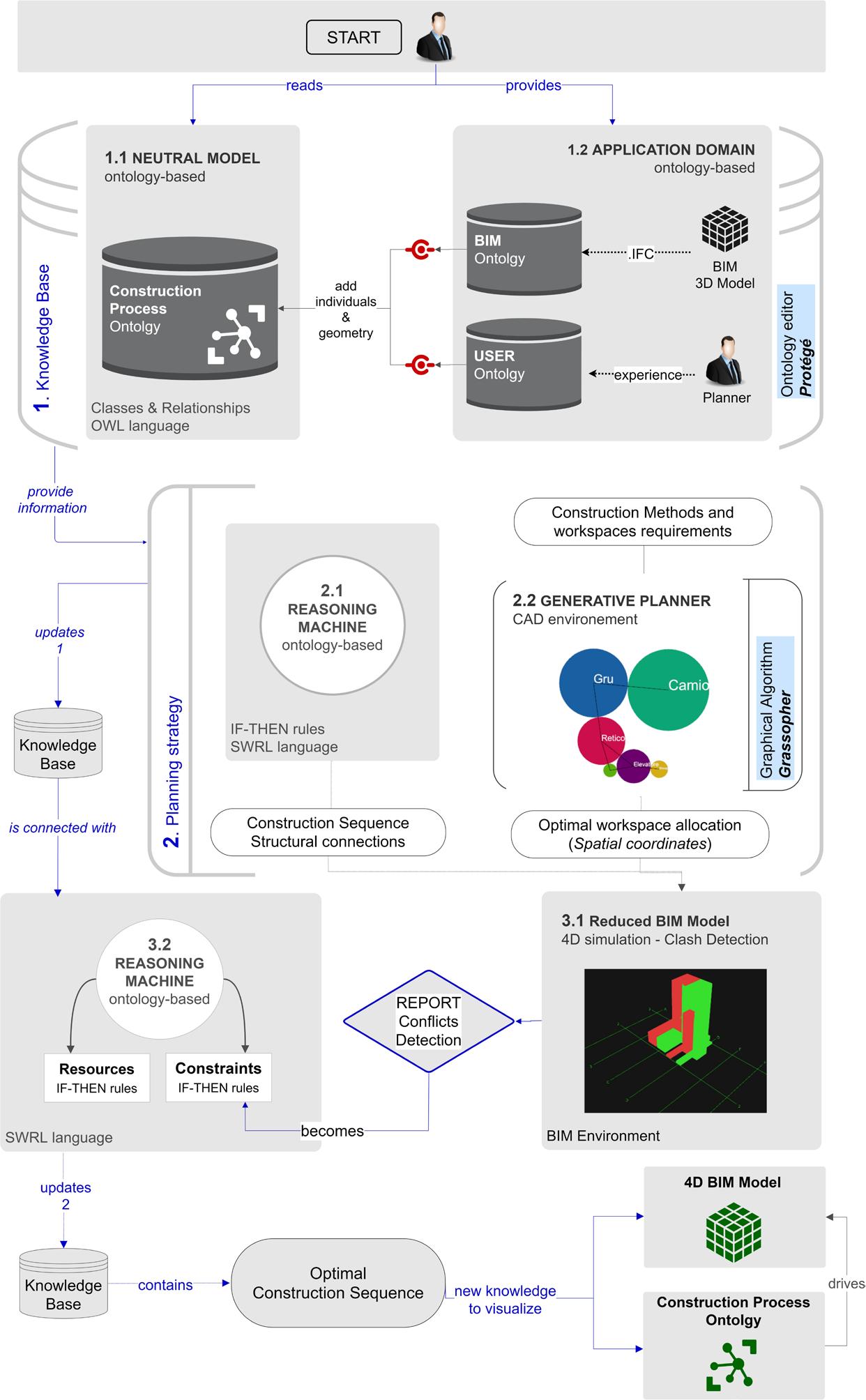
It represents the Earliest Construction Completion Sequence, the goal of the proposed expert system. Therefore, to recap, the expert system architecture is graphically represented in the figure below. The system architecture based on the ontologies clarifies the importance to have a predefined knowledge-base able to support automated reasoning mechanism.
•
8.10 Operational Framework of the proposed Expert System from the point of view of the ontology which drives the system to operate by means of a knowledge-base and a rule-engine
Akbas, R. 2004. Geometry-Based Modeling and Simulation of Construction Processes. STANFORD UNIVERSITY, CIFE Technical Report. Akinci, B., and J. Kunz, R. Levitt M. Fischer. 2000. “Representing Work Spaces Generically in Construction Method Models.” CIFE Working paper (Stanford Univeristy) DOI: 10.1061/(AS CE)0733-9364(2002)128:4(296). Akinci, B., H. Karimi, A. Pradhan, C. Wu, and G. Fichtl. 2010. “CAD and GIS interoperability through semantic web services.” Journal of Information Technology in Construction 13: 39–55. http://www.itcon.org/2008/3. Akinci, B., M. Fischer, and J. Kunz. 2000c. “Automated Generation of Work Spaces Required.” Edited by Stanford Univeristy. CIFE Working Paper. Allen, J., and G. Ferguson. 1997. Actions and events in interval temporal logic. ed., Kluwer O. Stock. http://dx.doi.org/10.1007/978-0-585-28322-7_7. Atkinson, C., M. Gutheil, and K. Kiko. 2007. “On the Relationship of Ontologies and Models.” Edited by Chair of Software Technology. ISBN: 978-3-88579-190-4. Azhar, S., M. Hein, and B. Sketo. 2008. “Building Information Modeling (BIM): benefits, risks and challenger.” Proceedings of the 44th ASC Annual Conference. Alabama. 627-634. Baader, F., D. Calvanese, D. Mcguiness, D. Nardi, and P., F. Patel-Schneider. 2003. Description Logic Handbook: Theory, Implementations, and Applications. Cambridge: Cambridge University Press. Bandwidth Market (2008), Bandwidth Market, Glossary http://www.bandwidthmarket.com/glossary/A7.html. Bargstädt, H., and A. Elmahdi. 2010. “Automatic generation of workspace requirements using qualitative and quantitative description.” Proceedings of the 10th International Conference on Construction Applications of Virtual Reality. Japan: K. Makanae, N. Yabuki, K. Kashiyama. ISBN: 978-4-9905537-0-8 C3000. http://convr2010.com/proceedings_contents Beetz, J., J. Van Leeuwen, and B. De Vries. 2009. “IfcOWL: A case of transforming EXPRESS schemas into ontologies.” Journal Artificial Intelligence for Engineering Design, Analysis and Manufacturing 23 (01): 89-101.DOI: 10.1017/S0890060409000122.
Benevolenskiy, A., K. Roos, P. Katranuschkov, and J. Scherer R. 2012. “Construction processes configuration using process patterns.” Advanced Engineering Informatics (Elsiever) (26): 727-736.DOI: 10.1016/j.aei.2012.04.003. Bordoli, A., and D. Baldwin. 2014. A Handbook for Construction Planning and Scheduling. West Sussex: John Wiley & Sons. ISBN: 978-0-470-67032-3. Brickley D, Guha RV (2003) RDF Vocabulary Description Language 1.0: RDF Schema. W3C Working Draft. http://www.w3.org/TR/PR-rdf-schema. Broekstra J, Klein M, Decker S, Fensel D, van Harmelen F, Horrocks I (2001) Enabling Knowledge Representation on the Web by Extending RDF Schema. In: Shen VY, Saito N (eds) 10th International World Wide Web Conference (WWW10). Hong Kong, pp 467–478. DOI: 10.1145/371920.372105. Buildingsmart. 2014. Industry Foundation Classes Release 4 (IFC4). http://www.buildingsmart-tech.org/ifc/IFC4/final/html/link/structural-connectivity.htm. Cai, X., Su, H. 2014. “Life Cycle Approach to Construction Workspace Modeling and Planning.” Journal of Construnction Engineering and Management (ASCE) March. DOI: 10.1061/(ASCE)CO.1943-7862.0000855 Chau, K., W., M. Anson, and J., P. Zhang. 2004. “Four-dimensional visualization of construction scheduling and site utilization.” Journal of Construction Engineering and Management (ASCE) 130: 598–606. DOI: 10.1061/(ASCE)0733-9364(2004)130:4(598). Chavada, R., N. Dawood, and M. Kassem. 2012. “Construction workspace management: the development and application of a novel nD planning approach and tool.” Journal of Information Technology Construction (ITcon) 12: 213–236. https://www.itcon.org/paper/2012/13. Cheng, T., and J. Teizer. 2013. “Real-time resource location data collection and visualization technology for construction safety and activity monitoring applications.” Automation in Construction 34: 3–15. DOI: 10.1016/j.autcon.2012.10.017. Cherneff, J., M., R. Logcher, and D. Sriram. 1991. “Integrating CAD with construction-schedule generation.” Journal of Computing in Civil Engineering (ASCE) 5 (1): 68-84. DOI: 10.1061/(ASCE)0887-3801(1991)5:1(64). CIOB. 2011. Guide to Good Practice in the Management of Time in Complex Projects. Oxford: Wiley-Blackwell. ISBN: 978-1-444-32961-2. Connor, O., and D. Martin. 2009. Importing Data into Protégé-OWL. Stanford Center for Biomedical Informatics Research. http://protege.stanford.edu/conference/2009/slides/ImportingDataProtegeConference2009.pdf. Cordier, J., M., and T. Porte. 1989. Shape Theory: Categorical Methods of Approximation. New York: Dover publications. ISBN: 9780486466231. Cox, S., and C. Little. 2016. “Time Ontology in OWL.” http://www.w3.org/2006/time.
Darwiche, A., R. Levitt, and B. Hayes-Roth. 1988. “OARPLAN: Generating Project Plans by Reasoning about Objects, Actions and Resources.” Artificial Intelligence for Engineering Design, Analysis and Manufacturing 2 (3): 169-181. DOI: 10.1017/S0890060400000639. Dawood, N., and S. Sikka. 2009. “Development of 4D based performance indicators in construction industry.” Engineering Construction and Architectural Management (Wiley) 16: 438–458. DOI: 10.1108/09699980910988357. Dawood, N., and Z. Mallasi. 2006. “Construction workspace planning: assignment and analysis utilizing 4D visualization technology,.” Computer-Aided Civil and Infrastructure Engineering (Elseiver) 21 (7): 498–513. DOI: 10.1111/j.1467-8667.2006.00454.x. Dawood, N., D. Scott, E. Sriprasert, and Z. Mallasi. 2005. “The virtual construction site (VIRCON) tools: An industrial evaluation.” Journal of Information Technology in Construction (Special Issue: From 3D to nD modelling) 10: 43-54. http://www.itcon.org/2005/5. Dhillon, R., K., M. Jethwa, and H., S. Rai. 2014. “Extracting Building Data from BIM with IFC.” International Journal on Recent Trends in Engineering and Technology 11 (1). DOI: 01.IJRTET.11.1.1500. Domingue J (1998) Tadzebao and WebOnto: Discussing, Browsing, and Editing Ontologies on the Web. In: Gaines BR, Musen MA (eds) 11th International Workshop on Knowledge Acquisition, Modeling and Management (KAW’98). Banff, Canada, KM4:1–20. http://ksi.cpsc.ucalgary. ca/KAW/KAW98/domingue/. Drogemulle, H., and R. Schevers. 2005. “Converting the Industry Foundation Classes to the Web Ontology Language.” 2005 First International Conference on Semantics, Knowledge and Grid, Beijing (China), 27-29 Nov. 2005. DOI: 10.1109/SKG.2005.59. Dudáš, M., O. Zamazal, and V. Svátek. 2014. “Roadmapping and nav- igating in the ontology visualization landscape.” Edited by Springer. Knowledge Engineering and Knowledge Management (K. Janowicz, S. Schlobach, P. Lambrix, and E. Hyvönen) 8876: 137–152. DOI: 10.1007/978-3-319-13704-9_11. Durkin, J. (1994), Expert Systems: Design and Development, Macmillan, New York. ISBN: 0-02330970-9. Dzeng, R., J., and I., E. Tommelein. 1997. “Boiler erection scheduling using product models and case-based reasoning,.” Journal of Construction Engineering and Management (ASCE) 123 (3). DOI: 10.1061/(ASCE)0733-9364(1997)123:3(338). Echeverry, D. 1991. “Factors for generating initial construction schedules.” Department of Civil Engineering, University of Illinois, PhD thesis, Urbana-Champaign. https://apps.dtic.mil/dtic/tr/ fulltext/u2/a243662.pdf. Elbeltadi, E., T. Hegazy, and A. Eldosouky. 2004. “Dynamic layout of construction temporary faciltities considering safety.” Journal of Construction Engineering and Management 130 (4): 534541. DOI: 10.1061/(ASCE)0733-9364(2004)130:4(534). El-Diraby. 2013. “Domain ontology for construction knowledge.” Journal of Construction Engineering and Management (ASCE) 768–784. DOI: 10.1061/(ASCE)CO.1943-7862.0000646.
El-Diraby, T., and h. Osman. 2011. “Automation in Construction.” A domain ontology for construction concepts in urban infrastructure products 20 (8): 1120–1132. DOI: 10.1016/j.autcon.2011.04.014. Ernstrom, B., and et al. 2006. The contractors’ Guide to BIM. Associated General Contractors of America. https://www.engr.psu.edu/ae/thesis/portfolios/2008/tjs288/Research/AGC_GuideToBIM.pdf Farquhar A, Fikes R, Rice J (1997) The Ontolingua Server: A Tool for Collaborative Ontology Construction. International Journal of Human Computer Studies 46(6):707–727. DOI: 10.1006/ijhc.1996.0121. Fensel D, van Harmelen F, Horrocks I, McGuinness DL, Patel-Schneider PF (2001) OIL: An ontology infrastructure for the Semantic Web. IEEE Intelligent Systems & their applications 16(2):38–44. DOI: 10.1109/5254.920598. Ferguson, J., Allen. 1997. “Actions and Event in interval temporal logic.” http://dx.doi. org/10.1007/978-0-585-28322-7_7. Fortineau, V., T. Paviot, L. Louis-Sidney, and S. Lamouri. 2012. “SWRL as a rule language for ontology-based models in power plant design.” DOI: 10.1007/978-3-642-35758-9_53. Friedman, E., H. 2003. Rule-Based Systems in Java – JESS IN ACTION. Greenwich: Manning Publications. ISBN: 9781930110892. Fu, B., N., F. Noy, and M., A. Storey. 2013. “Indented tree or graph? a usability study of ontology visualization techniques in the context of class mapping evaluation.” Edited by Springer. The Semantic Web (H. Alani, L. Kagal, A. Fokoue, P. Groth, C. Biemann, J. Parreira, L. Aroyo, N. Noy, C. Welty, and K. Janowicz) 8218: 117–134. DOI: 10.1007/978-3-642-41335-3_8. Gambatese, J., A., M. Behm, and J., W. Hinze. 2005. “Vviability of designing for construction worker safety.” Journal of Costruction Engineering and Management (ASCE) 131 (9): 10291036. DOI: 10.1061/(ASCE)0733-9364(2005)131:9(1029). Gasevic, D., Djuric, D., Devedzic, V., (2009). Model Driven Engineering and Ontology Development. Springer, ISBN: 978-3-642-00281-6; DOI: 10.1007/978-3-642-00282-3. Genesereth MR, Fikes RE (1992) Knowledge Interchange Format. Version 3.0. Reference Manual. Technical Report Logic-92-1. Computer Science Department. Stanford University, California. http://logic.stanford.edu/publications/genesereth/kif.pdf. Gómez-Pérez, A. & Corcho, O. (2002), “Ontology languages for the Semantic Web,” IEEE Intelligent Systems, Vol. 17, no. 1, pp. 54–60. DOI: 10.1109/5254.988453. Grosso, W., E., H. Eriksson, R., W. Fergerson, J., H. Gennari, S., W. Tu, and M., A. Musen. 1999. “Knowledge modeling at the millennium: The design and evolution of Protege-2000.” Technical Report, Stanford University, Institute for Medical Informatics, Standford. Gruber, T., R., (1992) Ontolingua: A Mechanism to Support Portable Ontologies. Technical report KSL-91-66, Knowledge Systems Laboratory, Stanford University, Stanford, California.
Gruber, T., R., (1993b) Toward principles for the design of ontologies used for knowledge sharing. In: Guarino N, Poli R (eds) International Workshop on Formal Ontology in Conceptual Analysis and Knowledge Representation. Padova, Italy. (Formal Ontology in Conceptual Analysis and Knowledge Representation) Kluwer Academic Publishers, Deventer, The Netherlands. https:// tomgruber.org/writing/onto-design.pdf. Gruber, T., R. 1995. “Toward principles for the design of ontologies used for knowledge sharing?” Edited by Elseiver. International Journal of Human-Computer Studies 43 (5): 907–928. DOI: 10.1006/ijhc.1995.1081. Gu, N., and K. London. 2010. “Understanding and facilitating BIM adoption in the AEC industry.” Automation in Construction 19: 988–999. DOI: 10.1016/j.autcon.2010.09.002. Guo, H., H. Li, G. Chan, and M. Skitmore. 2012. “Using game technologies to improve the safety of construction plant operations.” Accident Analysis and Prevention 48: 204–213. DOI: 10.1016/j. aap.2011.06.002. Guo, S., J. 2002. “Identification and resolution of work space conflicts in building construction.” Journal of Construction Engineering and Management (ASCE) 128: 287–295. DOI: 10.1061/(AS CE)0733-9364(2002)128:4(287). Guo, S., S., and C., W. Chan. 2011. “A comparison and analysis of some ontology visualization tools.” Edited by SEKE. Proceedings of the 23rd International Conference on Software Engineering & Knowledge Engineering. Knowledge Systems Institute Graduate School. 357–362. ISBN: 9781510841611. Halpin, H. & Shepard, H. (2006), Evolving Ontologies from Folksonomies:Tagging as a Complex System [Online] http://www.ibiblio. org/hhalpin/homepage/notes/taggingcss.html Hanson, B., and J. Hillier. 1984. The Social logica of space. Cambrige University Press. DOI: 10.1017/CBO9780511597237. Hegazy, T., M., and E. Elbeltagi. 1999. “EvoSite: Evolution-based models for site layout planning.” Journal of Computing in Civil Engineering (ASCE) 13 (3): 198–206. DOI: 10.1061/ (ASCE)0887-3801(1999)13:3(198). Heijst, G., A., Th. Schreiber, and B., J. Wielingua. 1997. “Using Explicit Ontolgies in KBS Development.” International Journal of Human-Computer Studies (Academic Press) 46: 183-292. DOI: 10.1006/ijhc.1996.0090. Hillier, B. 2007. Space is the Machine. London: Cambridge University Press. ISBN 978-09556224-0-3. Hori, M., Y. Nakamura, H. Satoh, K. Maruyama, T. Hama, S. Honda, T. Takenaka, and F. Sekine. 1995. “Knowledge-level analysis for elicting composable scheduling knowledge.” Artificial Intelligence in engineering (Elsiver Science Limited) 9: 253-264. DOI: 10.1016/0954-1810(95)00004-3. Horridge, M. 2011. “A Practical Guide To Building OWL Ontologies Using Protégé 4 and CO-ODE Tools Edition 1.3.” Guide, The University Of Manchester. https://gmakris.files.wordpress.com/2017/06/protegeowltutorialp4_v1_3.pdf
Horrocks, I. 2004. SWRL: A Semantic Web Rule Language Combining OWL and RuleML. https://www.w3.org/Submission/SWRL/. Horrocks I, Fensel D, Harmelen F, Decker S, Erdmann M, Klein M (2000) OIL in a Nutshell. In: Dieng R, Corby O (eds) 12th International Conference in Knowledge Engineering and Knowledge Management (EKAW’00). Juan-Les-Pins, France. (Lecture Notes in Artificial Intelligence LNAI 1937) Springer- Verlag, Berlin, Germany, pp 1–16. DOI: 10.1007/3540-39967-4_1. IDLab, Ghent Univeristy’s. 2013. IFC-to-RDF converter. IDLab. https://github.com/IDLabResearch/IFC-to-RDF-converter/wiki/IFC-to-RDF. Jagbeck, A. 1994. “MDA Planner: Interactive Planning Tool Using Product Models and Construction Methods.” Journal of Computing in Civil Engineering 8 (4): 536-554. DOI: 10.1061/ (ASCE)0887-3801(1994)8:4(536). Kalinowski, K. 2012. “Multistage decision making process of multicriteria production scheduling.” Journal of Machine Engineering 12 (3). ISSN (online): 2391-8071. http:// yadda.icm.edu.pl/baztech/element/bwmeta1.element.baztech-3b007c94-10cc-4d71bd24-135074647948 Kano, N. 1990. “A knowledge-based system for construction planning and scheduling: a prototype system based on the down-from the-top methodology.” The 7th International Symposium on Automation and Robotics in Construction. Bristol. 303-311. DOI: 10.22260/ ISARC1990/0039. Karp PD, Chaudhri V, Thomere J (1999) XOL: An XML-Based Ontology Exchange Language. Version 0.3. Technical Report. http://www.ai.sri.com/~pkarp/xol/xol.html. Kartam, N., A., and R., E. Levitt. 1990. “Intelligent planning of construction projects.” Journal of Computing in Civil Engineering (ASCE) 4 (2): 155-176. DOI: 10.1061/ (ASCE)0887-3801(1990)4:2(155). Kassem, M., N. Dawood, and R. Chavada. 2015. “Construction workspace management within an Industry Foundation Class-Compliant 4D tool.” Automation in Construction 52: 4258. DOI: 10.1016/j.autcon.2015.02.008. Katifori, A., C. Halatsis, G. Lepouras, A. Vassilakis, and E. Giannopoulou. 2007. “Ontology visualization methods – a survey.” ACM Computer Survey 39 (4). DOI: 10.1145/1287620.1287621. Katifori, A., E. Torou, C. Halatsis, G. Lepouras, and Vassilakis C. 2006. “A comparative study of four ontology visualization techniques in Protégé: Experiment setup and preliminary results.” International Conference on Information Visualisation. IEEE. 417–423. DOI: 10.1109/ IV.2006.3. Kim Jongeling, J., M. Fischer, C. Mourgues, and T. Olofsson. 2008. “Quantitative analysis of workflow, Temporary Structure Usage, and Productivity Using 4D Models.” Automation in Construction 17: 780-791. DOI: 10.1016/j.autcon.2008.02.006.
Kogut P, Cranefield S, Hart L, Dutra M, Baclawski K, Kokar M, Smith J (2002) UML for Ontology Development. The Knowledge Engineering Review 17(1):61–64. DOI: 10.1017/ S0269888902000358. Konig, M., and A. Marx. 2013. “Modeling and simulating spatial requiremts of construction activities.” Winter simulation conference 2013. R. Pasupathy et al. DOI: 10.1109/WSC.2013.6721694. Krishnamoorthy, C., S., and S. Rajeev. 1996. Artificial Intelligence and Expert Systems for Engineers. CRC Press LLC. ISBN: 978-0-8493-9125-5. Lambert, D., and C. Nowak. 2008. “The Mephisto Conceptual Framework” Command, Control, Communications and Intelligence Division DSTO Defence Science and Technology Organization. Australia. https://apps.dtic.mil/sti/pdfs/ADA515394.pdf. Lanzenberger, M., J. Sampson, and M. Rester. 2010. “Visualization in ontology tools.” Proceedings of the International Conference on Complex, Intelligent and Software Intensive Systems. IEEE. 705–711. DOI: 10.1109/CISIS.2009.178. Lee, K., J., H., W. Kim, J., K. Lee, and T., H. Kim. 1998. Case and constraint-based project planning for apartment construction. Vol. 19. 1 vols. AI Magazine. DOI: 10.1609/aimag.v19i1.1350. Liao, S.H. 2005. “Expert System methodologies and applications - a decade review from 1995 to 2004.” Expert Systems with Applications (Elsiever) (28): 93-103. DOI: 10.1016/j. eswa.2004.08.003. Lima, C., T. El-Diraby, and J. Stephens. 2005. “Ontology-based optimi- sation of knowledge management in e-construction.” Journal of Information Technology in Construction 10: 305–327. http://www.itcon.org/2005/21. Little, S., and C. Cox. 2016. Time Ontolgy in OWL. http://www.w3.org/TR/2016/WD-owl-time-20160712/. Lohmann, S., S. Negru, F. Haag, and E. Ertl. 2014. “Visualizing Ontologies with VOWL.” Semantic Web (IOS Press). DOI: 10.3233/SW-150200. Lopez, M., F., A., G. Pérez, and N. Juristo. 1997. “Methontology: From ontological art towards ontological engineering.” Ontological Engineering Spring Symp. Series. American Asso- ciation for Artificial Intelligence. 33-40. www.aaai.org/Papers/Symposia/Spring/1997/SS-97-06/SS97-06-005.pdf. Luke S, Heflin JD (2000) SHOE 1.01. Proposed Specification. Technical Report. Parallel Understanding Systems Group. Department of Computer Science. University of Maryland. http://www. cs.umd.edu/projects/plus/SHOE/ Ma, Z., Q. Shen, and J. Zhang. 2005. “Application of 4D for dynamic site layout planning and management of construction projects.” Automation in Construction 14: 369-381. DOI: 10.1016/j. autcon.2004.08.011. MacGregor R (1991) Inside the LOOM clasifier. SIGART bulletin 2(3):70–76 Maedche A, Motik B, Stojanovic L, Studer R, Volz R (2003) Ontologies for Enterprise Knowledge Management. IEEE Intelligent Systems 18(2):26–33. DOI: 10.1109/MIS.2003.1193654.
Mallasi, Z. 2006. “Dynamic quantification and analysis of the construction workspace congestion utilising 4D visualisation.” Automation in Construction (Elseiver) (15): 640–655. DOI: 10.1016/j.autcon.2005.08.005. Manola F, Miller E (2003) RDF Primer. W3C Working Draft. http://www.w3.org/TR/rdf-primer/ McGuinness, N., F. 2001. “Ontology Development 101: A Guide to Creating Your Fisrt Ontology.” Standford Univerisity, Standford. https://protege.stanford.edu/publications/ontology_development/ontology101.pdf. Mikulakova, E., M. Konig, E. Tauscher, and Beucke. K. 2010. “Knowledge-based schedule geenration and evaluation.” Advanced engineering Informatics 24: 389-403. DOI: 10.1016/j. aei.2010.06.010. Mohan, S. 1990. “Expert systems applications in construction management and engineering.” Journal of Construction Engineering and Management (ASCE) 116 (1): 87-99. DOI: 10.1061/(ASCE)0733-9364(1990)116:1(87). Moon, H., H. Dawood, and L. Kang. 2014. “Development of workspace conflict visualization system using 4D object of work schedule.” Advanced Engineering Informatics (Elseiver) 28: 50–65. DOI: 10.1016/j.aei.2013.12.001. Moon, H., H. Kim, C. Kim, and L. Kang. 2014. “Development of a schedule workspace interference management system simultaneously considering the overlap level of parallel schedules and workspaces.” Automation in Construction 39: 93–105. DOI: 10.1016/j.autcon.2013.06.001. Moon, H., H. Kim, V. R. Kamat, and Kang L. 2015. “BIM-based Construction Scheduling Method Using Optimization Theory for Reducing Activity Overlaps.” Journal of Computing in Civil Engineering (ASCE) 29 (3). DOI: 10.1061/(ASCE)CP.1943-5487.0000342. Moon, H., L. Kang, N. Dawood, and S. Ji. 2009. “Configuration method of health and safety rule for improving productivity in construction space by multi-dimension CAD system.” Proceedings of ICCEM/ICCPM. Korea. 27-30. Morad, A., A., and Y., J. Beliveau. 1991. “Knowledge-based planning system.” Journal of Construction Engineering and Management (ASCE) 117 (1): 1-12. DOI: 10.1061/ (ASCE)0733-9364(1991)117:1(1). Motawa, I., and A., Almarshad. 2012. “A Knowledge-based BIM system for building maitenance.” Automation in Construction (Elseiver) 29: 173-182. DOI: 10.1016/j.autcon.2012.09.008. Motta, E. 2000. “The knowledge modelling paradigm in knowledge engineering.” Handbook of Software Engineering and Knowledge Engineering (World Scientific Publishing) 1: 1-29. DOI: 10.1142/9789812389718_0024. Mun, D., and K. Ramani. 2011. “Knowledge-based part similarity measurement utilizing ontology and multi-criteria decision making technique.” Advanced Engineering Informatics 119130. DOI: 10.1016/j.aei.2010.07.003.
Navinchandra, D., D. Sriram, and R. Logcher. 1988. “GHOST: project network generator.” Journal of Computing in Civil Engineering (ASCE) 2 (3): 239-254. DOI: 10.1061/ (ASCE)0887-3801(1988)2:3(239). Nourian, P., S. Rezvani, and S. Sariyildiz. 2013. “Designing with Space Syntax A configurative approach to architectural layout, proposing a computational methodology.” eCAADe 31. 357-365. ISBN: 978-94-91207-04-4. Noy, N., R., W. Fergerson, and M., A. Musen. 2000. “The knowledge model of Protege-2000: Combining interoperability and flexibility.” Proceedings of the 12th international conference on knowledge engineering and knowledge management. France. DOI: 10.1007/3-540-399674_2. Noy, N.F. & McGuinness, D.L. (2001), Ontology Development 101: A Guide to Creating Your First Ontology, Knowledge Systems Laboratory, Stanford University, CA. OpenBIM, BuildingSMART. 2016. ifc-overview. http://www.buildingsmart-tech.org/specifications/ifc-overview. Rajpathak, D. 2001. “The Task Ontology Component of the Scheduling Library.” Knowledge Media Institute (The open Univeristy). Pilot Study. Rajpathak, D., E. Motta, and R. Roy. 2000. “A Generic Task Ontolgy for Scheduling Applications.” http://projects.kmi.open.ac.uk/akt/publication-pdf/generictaskontology.pdf. Riley, D., R., and V. Sanvido. 1997. “Space planning method for multistory building construction.” Journal of Construction Engineering and Management (ASCE) 171–180. DOI: 10.1061/(ASCE)0733-9364(1997)123:2(171). Sacks, R., O. Rozenfeld, and Y. Rosenfeld. 2009. “Spatial and Temporal Exposure to Safety Hazards in Construction.” Journal of Cosntruciton Engineering and Management (ASCE) 135 (8): 726-736. DOI: 10.1061/(ASCE)0733-9364(2009)135:8(726). Said, H., and G. Lucko. 2016. “Float Types in Construction Spatial Scheduling.” Journal of Construction Engineering and Management (ASCE) 142 (12): 1-12. DOI: 10.1061/(ASCE)CO.19437862.0001202. Sanvido, D. R. Riley and V. E. 1995. “Patterns of Construction-Space Use in Multistory Buildings.” J. Constr. Engine. Manage. 123 (4): 464-473. DOI: 10.1061/(ASCE)0733-9364(1995)121:4(464). Sayed, K., A. Turner, B. Hillier, S. Iida, and A. Penn. 2014. Space syntax methodologies. Edited by Bartlett School of Engineering Architecture. London. Shaked, O., and A. Warszawski. 1995. “Knowledge based system for construction planning of high-rise buildings.” Journal of Construction Engineering and Management (ASCE) 110 (2): 172182. DOI: 10.1061/(ASCE)0733-9364(1995)121:2(172). Smith, S., F., and M., A. Becker. 1997. “An Ontolgy of Constructing Scheduling Systems.” AAAI Symposium on Ontological Engineering. Stanford: AAAI Press. https://www.aaai.org/Papers/Symposia/Spring/1997/SS-97-06/SS97-06-016.pdf.
Smith, S., F., G. Cortellessa, D., W. Hildum, and D., W. Ohler. 2005. “Using a scheduling domanin ontolgy to compute user-oriented explanations.” Planning, Scheduling, and Constraint Satisfaction: From theory to Practise. Song, Y., and D. Chua. 2005. “Detection of spatio-temporal conflicts on a temporal 3D space system.” Advanced Engineering Software (36): 814–826. DOI: 10.1016/j.advengsoft.2005.03.025. Sowa JF (1999) Knowledge Representation: Logical, Philosophical, and Computational Foundations. Brooks Cole Publishing Co., Pacific Grove, California ISBN: 0-534-94965-7. Steuer, J. 1993. “Defining virtual reality: dimensions determining telepresence.” Journal of Communication 42: 73–93. DOI: 10.1111/j.1460-2466.1992.tb00812.x. Su, X., R. Andohar, J. Pan, and A. Kandil. 2012. “GIS-based dynamic construction site material layout evaluation for building renovation projects.” Automation in Construciton 27: 40-49. DOI: 10.1016/j.autcon.2012.04.007. Sure Y, Erdmann M, Angele J, Staab S, Studer R, Wenke D (2002a) OntoEdit:Collaborative Ontology Engineering for the Semantic Web. In: Horrocks I, Hendler JA (eds) First International Semantic Web Conference (ISWC’02). Sardinia, Italy. (Lecture Notes in Computer Science LNCS 2342) Springer- Verlag, Berlin, Germany, pp 221–235. DOI: 10.1007/3-540-48005-6_18. Swartout B, Ramesh P, Knight K, Russ T (1997) Toward Distributed Use of Large- Scale Ontologies. In: Farquhar A, Gruninger M, Gómez-Pérez A, Uschold M, van der Vet P (eds) AAAI’97 Spring Symposium on Ontological Engineering. Stanford University, California, pp 138–148. https://www.aaai.org/Papers/Symposia/Spring/1997/SS-97-06/SS97-06-018.pdf. Tah, J., H., M., V. Carr, and R. Howes. 1999. “Information modeling for case-based construction planning of highway bridge proj- ects.” Advances in Engineering Software (Elseiver) 30 (7): 495-509. DOI: 10.1016/S0965-9978(98)00128-8. Thabet, W., Y., and Y., J. Beliveau. 1994. “Modeling work space to schedule repetitive floors in mul- tistory buildings.” Journal of Construction Engineering and Management 120 (1): 96–116. DOI: 10.1061/(ASCE)0733-9364(1994)120:1(96). Thomas, H., R., D., R. Riley, and S., K. Sinha. 2006. “Fundamental principles for avoiding congested work areas - a case study.” Practice Periodical on Structural Design and Construction (11): 197–205. DOI: 10.1061/(ASCE)1084-0680(2006)11:4(197). Wang, H., and F. Boukamp. 2011. “Ontology-based representation and reasoning framework for supporting job hazard analysis.” Journal of Computing in Civil Engineering (ASCE) 25 (6): 442–456. DOI: 10.1061/(ASCE)CP.1943-5487.0000125. Wikipedia. 2017. Industry Foundation Classes. https://en.wikipedia.org/wiki/Industry_Foundation_Classes. Winch, G., M., and S. North. 2006. “Critical space analysis.” Journal of Construcition Engineering and Management 132: 473–481. DOI: 10.1061/(ASCE)0733-9364(2006)132:5(473).
Zhang, S., F. Boukamp, and J. Teizer. 2015. “Ontology-based semantic modeling of construction safety knowledge: towards automated safety planning for job hazard analysis (JHA).” Automation in Construction (Elseiver) 52: 29–41. DOI: 10.1016/j.autcon.2015.02.005. Zhang, S., J. Teizer, N. Pradhananga, and C., E. Eastman. 2015. “Workforce location tracking to model, visualize and analyze workspace requirements in building information models for construction safety planning.” Automation in Construction 60: 74-86. DOI: 10.1016/j.autcon.2015.09.009. Zhong, B., L. Ding, H. Luo, Y. Zhou, Y. Hu, and H. Hu. 2012. “Ontology-based semantic modeling of regulation constraint for automated construction quality compliance checking.” Automation in Construction (Elsevier) (28): 58–70. DOI: 10.1016/j.autcon.2012.06.006. Zhou, Z., Y., M. Goh, and L. Shen. 2016. “Overview and Analysis of Ontology Studies Supporting Development of the Construction Industry.” Journal of Computing in Civil Engineering (ASCE). DOI: 10.1061/(ASCE)CP.1943-5487.0000594. Zouein, P., P., and I., D. Tommelein. 1999. “Dynamic layout planning using a hybrid incremental solution method.” Journal of Construction Engineering and Management 125 (6): 400-408. DOI: 10.1061/(ASCE)0733-9364(1999)125:6(400). Zozaya-Gorostiza, C., C. Hendrickson, and D., R. Rehak. 1989. Knowledge-Based Process Planning for Construction and Manufacturing. Academic Press. ISBN: 0127819002.
ricerche | architettura, pianificazione, paesaggio, design
Published Books
1. Alessandro Brodini, Lo Iuav ai Tolentini: Carlo Scarpa e gli altri. Storia e documenti, 2020 2. Letizia Dipasquale, Understanding Chefchaouen. Traditional knowledge for a sustainable habitat, 2020
Nowadays, there is an increasing recognition of the value of knowledge management in the construction projects and ontology-based semantic modelling is seen as an important means of addressing this problem, even if a knowledge-base which maps the construction planning and scheduling domains, in a formal and machine-readable way, is still missing. Addressing this issue, the book is divided in two parts. Part I, theory, is a theoretical introduction of on ontologies concepts and expert systems. Part II, application, presents a research of ontologies development for semantic modelling of construction scheduling, workspace, product and time domains. The last chapter presents the architecture of an ontology-based expert system, to show how ontologies can support automated planning mechanisms.
Vito Getuli holds his doctorate in Civil and Environmental Engineering from University of Florence and University of Braunschweig (Germany). He is research fellow and adjunct professor at Department of Architecture (UniFI) with expertise in Construction Management, BIM, Artificial Intelligence, VR/AR.
ISBN 978-88-5518-183-9 (Print) ISBN 978-88-5518-184-6 (PDF) ISBN 978-88-5518-185-3 (XML) DOI 10.36253/978-88-5518-184-6


