COVER STORY The Sky Habitat basement is surrounded by a series of tightly-knit Contiguous Bored Piles (CBPs) and skin walls. The CBPs, each measuring 600 mm in diameter, form the basement perimeter foundation walls. The CBP wall method was chosen, taking into consideration the given twobasement construction and the site constraints, and also because it offers the best and safest solution for controlling ground movement or deformation, during excavation, while the skin walls were introduced in order to manage the groundwater seepage.
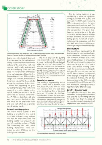
Compression tie beams were introduced at Level 14 while tension tie post-tensioned beams were introduced at Basement 2 to make sure that the load paths are closely looped effectively.
beams were introduced at Basement 2 to make sure that the load paths are closely looped effectively. The correct detailing of the splay shear walls was necessary as they play an important role in transferring down the load safely. The reinforcement for the splay shear wall was designed, based on the forces obtained from 3-D modelling, using ETABS software, and detailed in the proper way so that it was able to achieve the mentioned design intent. Other than supporting the gravity loading, the splay shear walls were designed to provide stability to the overall building as well as to the lift core walls and staircase storey shelters. A 700 mm thick floor slab acts as a diaphragm to distribute the lateral forces to the splay shear walls and core walls effectively, to provide overall building stability. Lateral resisting system The overall lateral stability of the building is provided by the central core walls, staircase storey shelters and also the splay shear walls. The building stability was analysed with the 3-D modelling software, ETABS. The inter-storey drift and overall building displacement were controlled to within 1/500, as per the building code statement.
16
The mode shape of the building was considered, where its movement in mode 1 and mode 2 is translational while that in mode 3 is rotational. The effective orientation of the lateral resisting system provides high stiffness to the building, ensuring low natural frequency of the building and, in turn, the comfort of the occupants, even at the highest level. Foundation system The building is supported by a total of 470 bored piles, of 800 mm, 1000 mm, 1200 mm, 1350 mm and 1500 mm diameter, that are cast deep under the building. Out of this total, there are 184 tension piles that have been installed to resist the hydrostatic uplift stresses below the podium area, where there is too little building mass to suppress the floating forces generated by underground water pressure.
3D modelling software was used for transfer truss design.
THE SINGAPORE ENGINEER October 2016
Substructure The lowest floor framing, at the B2 level, consists of a conventional castin-situ reinforced concrete flat slab, with a uniform thickness of 500 mm, supported by pilecaps of various sizes. The 500 mm thick slab is designed to overcome the large amount of hydrostatic uplift stresses existing underneath the lowest structures. Integrally waterproofed concrete was used at the B2 slab to prevent underground water seepage or migration through the sectional thickness. The B1 slab thickness is generally 250 mm, with pockets of 150 mm, 200 mm and 275 mm thicknesses, catering for various floor framing for different needs. Level 14 transfer truss The loading from the upper level was determined by using both the column load take and 3-D modelling software for transfer truss design. The design of the truss elements and connection detail requirements were based on BS5950.