

Metering & Energy Management Control Standards Off-Peak & Dual Fuel Wiring Diagrams Updated April 2021 2 Notes
All types of electrical self contained metering, single socket, multiple sockets, residential & commercial will be an approved heavy duty, ringless type socket with a lever by pass, clamping jaw, 200 Amp minimum interior.

All CT or current transformer type metering will be purchased and installed by Crow Wing Power. This CT metering will be outside, mounted to the transformer, pedestal or overhead pole top.
All CT services, 600 Amps and less will have a circuit breaker type disconnect. (See #5, next page)
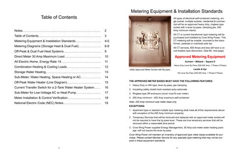
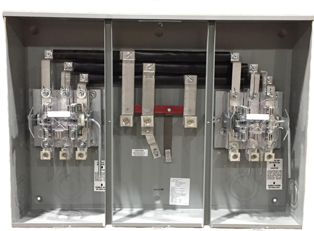
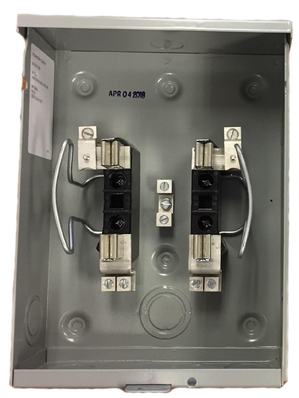
Durham ~ Milbank ~ Square D Heavy Duty Lever By-Pass (200-400 Amp, 1 Phase-3 Phase) Landis & Gyr HQ Lever By Pass (200 400 Amp, 1 Phase 3 Phase) THE APPROVED METER BASES MUST HAVE THE FOLLOWING FEATURES:
Utility Approved Meter Socket with By pass
Heavy Duty or HW type, lever by pass, jaw clamping
Insulating safety shield track resistant poly-carbonate
Ringless type 3R enclosure (cover must fit over meter)
200 Amp minimum 400 Amp maximum self contained
200 Amp minimum size meter base only EXCEPTIONS:
Apartment type or stacked multiple type metering shall meet all of the requirements above with exception of the 200 Amp minimum ampacity.
Temporary Services that will be removed and replaced with an approved meter socket will not be required to have the by pass lever. These are true temporary services that will be removed within a reasonable time period. 3. Crow Wing Power supplied Energy Management, 30 Amp sub meter water heating package will not require the lever by pass. Crow Wing Power will maintain an inventory of approved type meter bases available for purchase. Please contact Member Service for any specialty type metering that may not be covered in these equipment standards.
1. All metering equipment will be of the approved type and be mounted outside and be readily accessible.
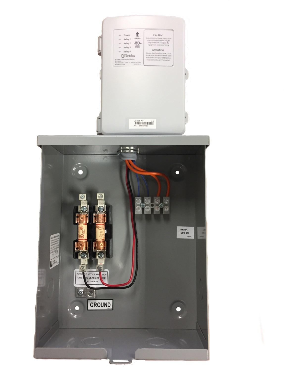
2. All Energy Management equipment must be outside and wired adjacent to the metering. Power for controls is derived from load side of Energy Management meter. Energy management equipment shall not contain any other wiring. Utility Controls are mounted in a vertical position.
3. All metering and Energy Management equipment shall be readily accessible and mounted at height of not less than 3 feet to the bottom and 6 feet to the top of the meter base.
4. All metering and Energy Management equipment shall be supplied with an equipment bonding conductor and grounding to the NEC standards.
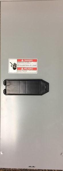
5. All direct, self contained, and CT type metering 600 Amps and less will have a service rated, weather proof, breaker type disconnect wired and attached to the load side of the meter base, mounted below, to the side, or directly behind the meter base on the pedestal. This includes irrigation equipment.
6. 3-phase, 120/240v self contained services are required to have the conductor with the higher voltage to ground (wild leg) connected to the right side meter terminal as per the NEC in all 3-phase meter bases (for accurate metering purposes).
• Crow Wing Power must have a copy of the wiring affidavit on file prior to any meter installation.
• Any electrical service not meeting these approved equipment & installation standards will not be energized.
• Services energized not meeting the requirements will be subject to disconnection until they have been corrected.
• All metering and associated Energy Management equipment that becomes enclosed or inaccessible will be moved to an outside location at the owner’s expense!
• See page 18 for Meter Installation & Control Verification
• All wiring according to the National Electrical Code.
• Copper to aluminum connections are not allowed.
Low Voltage Controls - Storage Heat or Dual Fuel
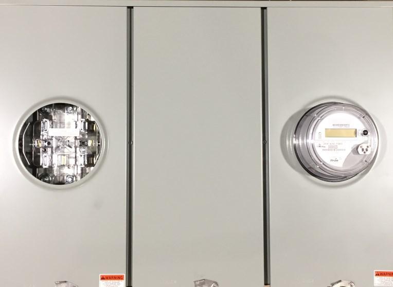
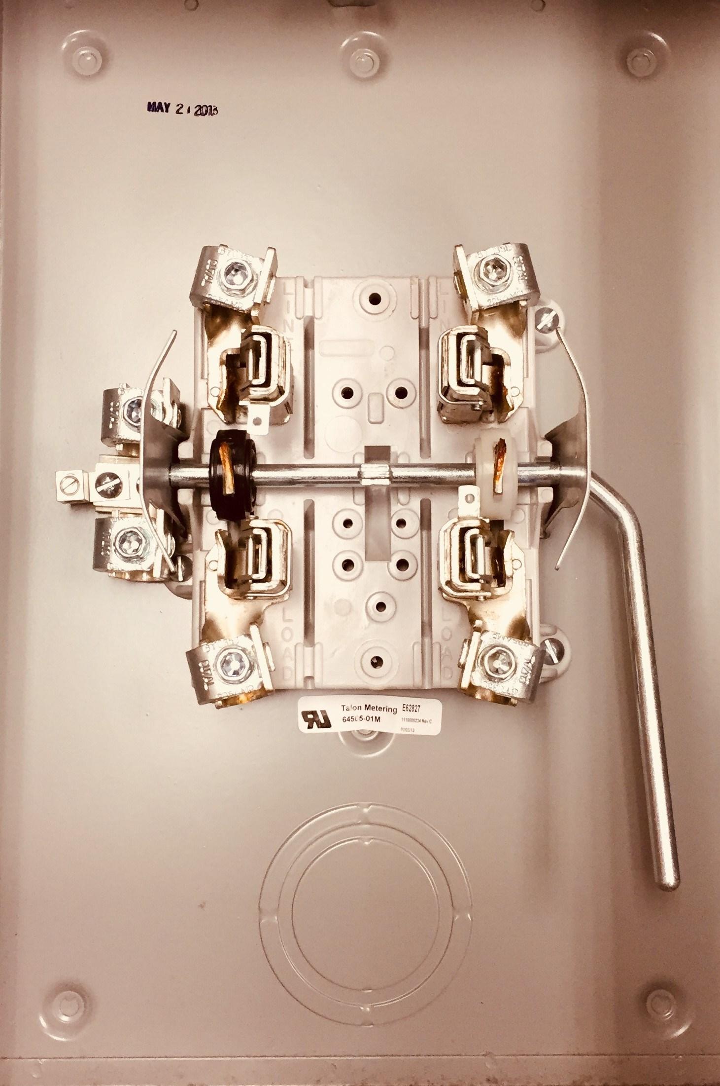
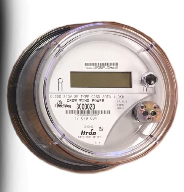
200 Amp Utility Approved Double Meter Socket Standard Form 2S Meter
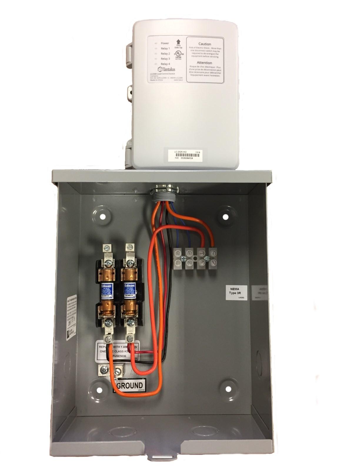
Utility Control
Utility Box
Utility Transformer
Energy Management Controls General Service Panel
Weather Proof Service Rated Circuit Breaker Type Disconnect
Energy Management Panel
Line Voltage Controls - Dual Fuel
Note: with this type of control, there can no longer be any separately controlled storage water heating from the Dual Fuel Panel.
Utility Control
Storage + Dual Fuel + General Service
Approved Type Dual Meter Socket with By-Pass Lever
Utility Transformer General Service Panel Energy Management Panel
Off Peak Panel
Utility Transformer Dual Fuel Panel
General Service Panel
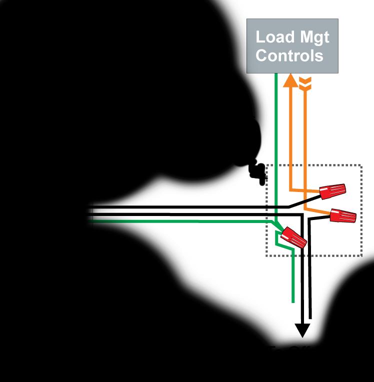
• All low voltage wiring will be controlled directly from the outside Utility Box that is connected to the Energy Management meter base, wired directly to the electric heating or AC HP equipment.
• Electric Furnaces, Plenum Heaters, Boilers, ASHP, AC units and listed manufactured low voltage control packages used to control electric heating/gas and ASHP will be allowed, provided that they are factory supplied and connected to the equipment.
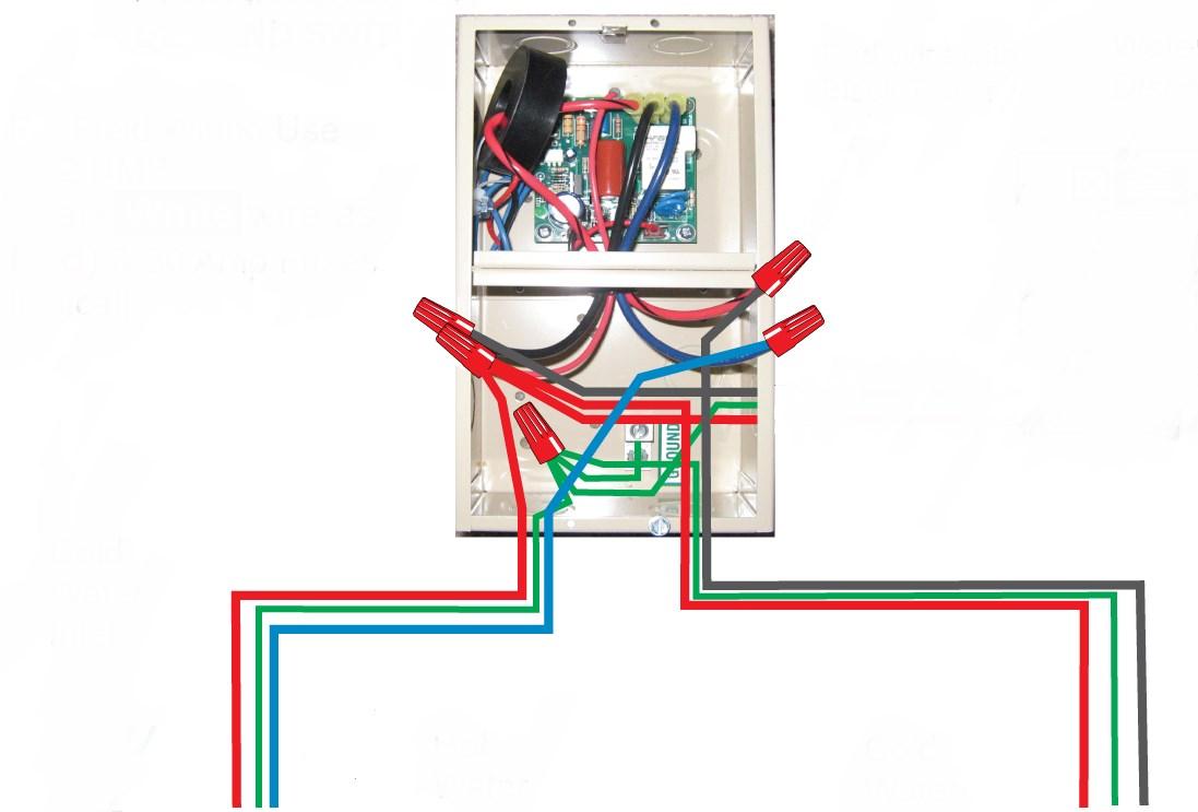
• The preferred method of all low voltage control of equipment is to utilize manufacturers contact point N.O. (normally open contacts) marked LM, Power Company, Utility Control points or the “blue” wires. Note: please mark or tape your control wires BLUE
• Contractor supplied or manufactured control packages, relays, daisy chained or interconnected systems, or any other controls mounted inside will not be allowed on the program. Note: the 11 pin 240 volt relay has the capability of 3 sets of N.O. contact points, with 2 relays there are 6 sets of contacts.
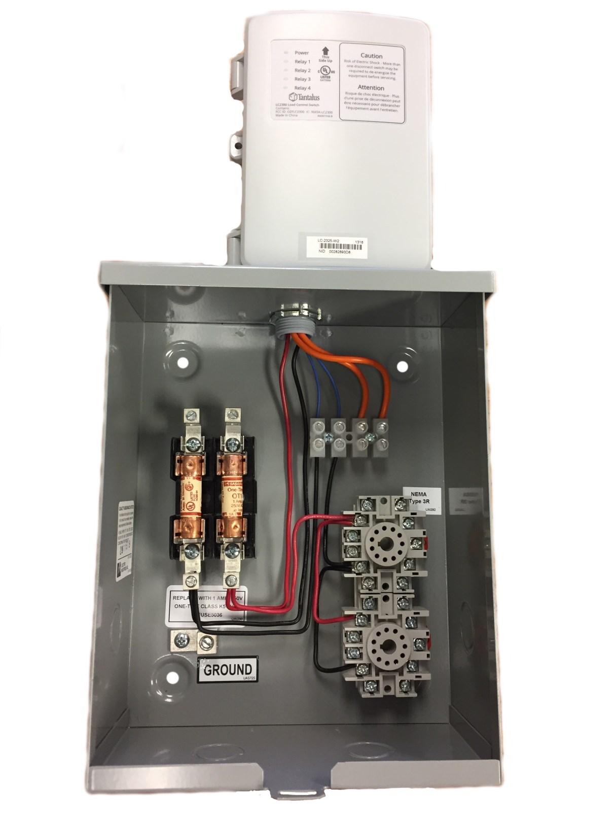
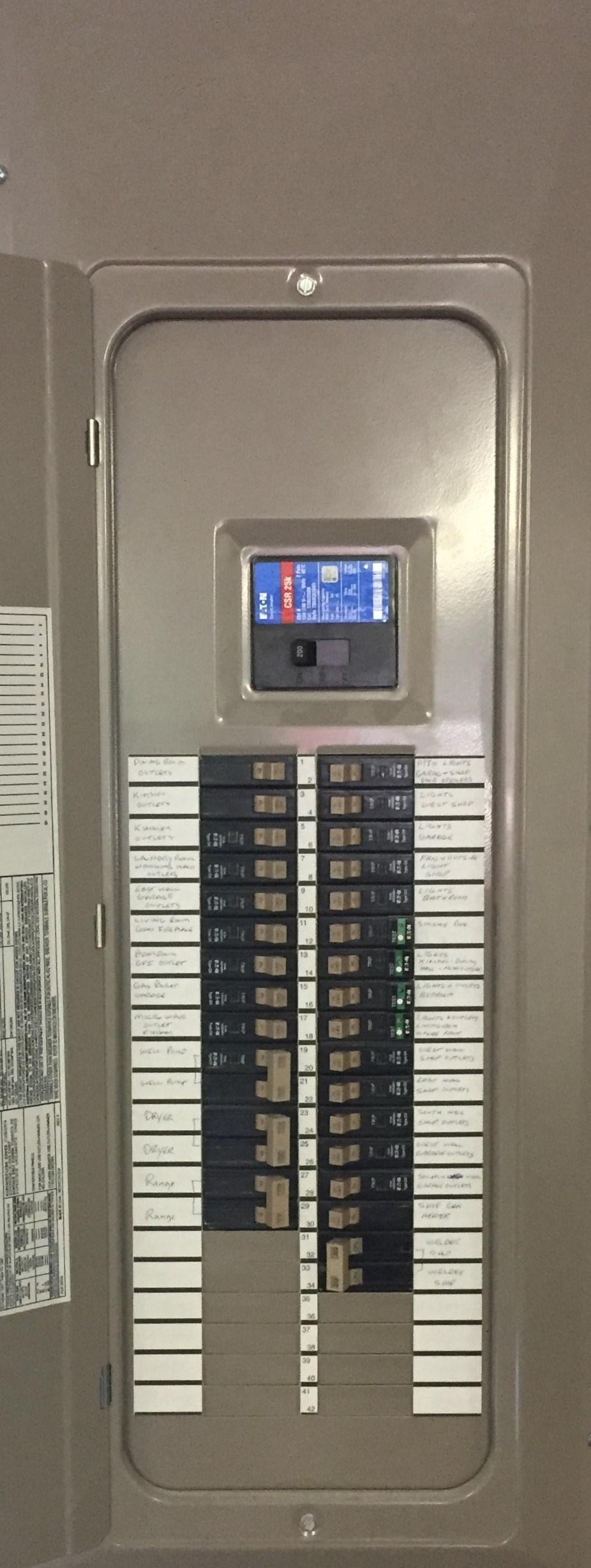
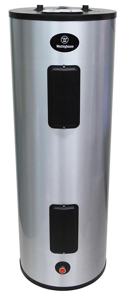
Note: Power for the Water Heater is derived from the 30 Amp breaker in the Off-Peak or Dual Fuel Heating Panel.
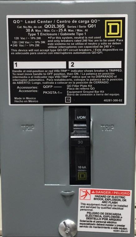
30 Amp 240 Volt 2 Pole Circuit Breaker
Grounding Electrode Connection
Note: these connections can be made in either the panel board or a J box
Off Peak Water Heater
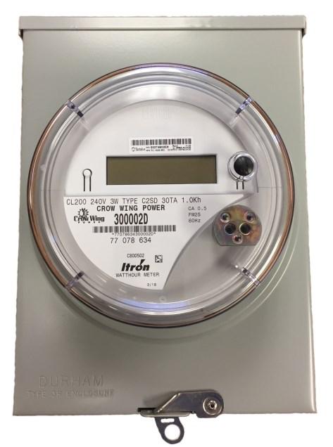
Sub-Meter for Water Heater or Space Heating
Note: 240 volt load only. Maximum ampacity 60 Amps. Crow Wing Power Special Lugs in Meter base Inside Building
Outside ”
Meter “D
Wall Wire typically installed in PVC conduit sized to the load Controlled Load General Service Panel
-
Power from the General Service Panel to the existing disconnect for the AC or Heat Pump
Size conductors to the fused capacity of the circuit. Maximum 60 Amp 240 volts.
Utility Control
Mounted Outside
Note:
Low Voltage AC or HP Compressor Control
Barrier to separate Line & Low Voltages
All Energy Management Meter installations are considered complete only after the installing Electrician/Owner Installer has completed all of the necessary wiring and a Crow Wing Power Electrician has verified that the control wiring is correct.
It is the responsibility of the Electrician/Owner Installer to schedule an appropriate time within reason for the Crow Wing Power Electrician to inspect the installation for the following:
• All metering equipment & control wiring mounted outside must be completed.
• All control wires must be buried & terminated, in an approved junction box or panel, at the Crow Wing Power control box & in the building. This wiring must be inspected for compliance with the National Electrical Code.
• All heating & water heating equipment intended to be served by the Energy Management meter to be installed, must be wired & ready for use.
• Only approved type heating equipment designed for and factory wired for an inter-connection type control of other heating equipment (Daisy Changed) will be allowed. (Please contact Crow Wing Power for equipment approval)
• All Energy Management electrical panels for heating, AC and water heating must be wired for approved loads only and completed with the covers installed. These panels will be sealed with a Crow Wing Power panel cover seal.
Note: the metering will be installed upon completion of the above criteria.
• All Energy Management Rebates will be based on meeting the above criteria and filing the proper forms.
• Requests for installation of a Energy Management meter, before all of the above criteria are met, will result in a $75.00 per return trip charge.
Note: this charge may be waived under certain conditions.
• Only approved Energy Management type equipment, supplied by Crow Wing Power will be installed. Any other control equipment installed inside or outside WILL NOT BE CONNECTED.

• Exception to Crow Wing Power supplied equipment: for Storage Electric Floor Cable Heating, the Electro Industries PI DC coil, 30 Amp relay panel with sequencing will be purchased by the installer.
Note: Low Voltage
• Customer supplies wiring from the load side of the meter equipment and it must be sized in accordance with the 2017 NEC (see charts below)
• Red warning ribbon is placed at least 12 inches above underground service wiring.
• All 120/240 volt feeder wiring (after the service disconnect) must include an equipment grounding conductor (4 wire)
Table 310.15(B)(7)(2) Annex D Page 70 800 This chart is ONLY for dwelling unit, general service panels: NOT OFF-PEAK or DUAL FUEL
Conductor types & sizes for 120/240 volt, single-phase services & feeders.
Wire types: RHH, RHW 2, THHN, THHW, THW, THW 2, THWN, THWN 2, XHHW, XHHW-2, SE, USE, USE-2.
Service Rating (Amps): Aluminum Wire: Copper Wire:
100 Amp #2 AWG #4 AWG
150 Amp # 2/0 AWG #1 AWG 200 Amp # 4/0 AWG # 2/0 AWG
225 Amp 250 kcmil # 3/0 AWG 400 Amp 600 kcmil # 400 kcmil
Table 310.15 (B)(16) This chart must be used for all non-dwelling general loads including: Off Peak & Dual Fuel Services & Feeders (Direct Metered and Sub Metered Loads)
Service Rating (Amps): Aluminum Wire: Copper Wire:
100 Amp # 1 or 1/0 AWG #3 or #2 AWG
150 Amp # 3/0 or 4/0 AWG # 1/0 AWG
200 Amp *250 kcmil # 3/0 AWG
225 Amp 300 kcmil # 4/0 AWG
400 Amp 2 x 250 kcmil 2 x 3/0 AWG
*If 4/0 Aluminum is used for a 200 Amp Service or Feeder a calculated load must be provided to Crow Wing Power & the electrical inspector.
PO Box 507 17330 State Highway 371 N Brainerd, MN 56401 218.829.2827 1.800.648.9401