
20 minute read
BIM-based parametric adaptive design of kinetic shell facades in buildings

Ibrahim Motawa1** and Khaled Habach2
1Belfast School of Architecture and Built Environment, Ulster University, Belfast, UK 2Department of Architecture, Strathclyde University, Glasgow, UK
Advertisement
E-mail: 1i.motawa@ulster.ac.uk , 2khaled.habach@strath.ac.uk **(corresponding author)
Abstract - Design processes need to consider building adaptation to the changing conditions of usage, environmental changes, and the changes in users behaviour. Technological advancements have allowed to develop and access distinct approaches in design, where interactive physical mechanisms can be built that respond to their environmental and surrounding conditions. This paper investigates the relationship between the technological advancement in kinetic shell structures over time, examines different kinds of adaptive kinetic shells, highlights the importance and advantages of these structures, and proposes a BIM-based parametric adaptive design for multi-functional kinetic shell facades. The paper proposes a parametric workflow to test adaptive kinetic façades for curvilinear buildings to enhance the sustainable performance of buildings by reducing solar radiation intake based on the location of the building and the time of the day. This workflow utilises energy simulation of an architectural structure using kinetic façade system to optimise the best solution of daylighting adequacy and thermal performance. The workflow was validated by conducting a case study. The study concluded that the developed parametric workflow can enhance the efficiency of architectural buildings on multiple sustainable and financial aspects. The study also approved the advantages of adaptive kinetic shell structure in multiple locations and under different environmental conditions.
Keywords - BIM, adaptive design, kinetic shell facades
I INTRODUCTION Adaptive architecture involves a range of design fields from designs for media facades to eco buildings, dorm responsive art installations to stage design and from artificial intelligence to ubiquitous computing [1]. When applying adaptive architecture, the design structure, behaviour or resources can be changed according to a programmatic demand by the designer. Few existing buildings around the world (e.g. bionic tower, Dubai city tower, Illinois tower, etc.) have the ability to dynamically move as a whole structure or partially rotate. In this regard, Kinetic architecture is a design approach in contemporary architecture which explores the physical transformation of a building with the objective to redefine traditional applications of motion through technological innovation. The use of robotics, mechanics and electronics is essential to this new approach. The concept of “Kinetic Architecture” has changed architectural design to be more transformable, dynamic, and interactive to achieve many design objectives including environmental goals, social interaction, and sense of place [2]. This paper will focus on the adaptive design in the kinetic (dynamic) shell façade systems.
Building façades are considered to be the most important protection structure from the external environment; such as sun glare and direct heat gain. The advancement of Building façade systems helps in changing the traditional static design of façades as a cover only to play a more active role; such as integrating photovoltaic cells to help generate energy than just save energy [3]. An efficient building envelope enhances daylight uniformity and improves energy performance of the building. However, designing facades is a challenging task for architects when considering multiple objectives; e.g. to reduce energy consumption and improve the occupant’s health [4].
This paper introduces a BIM-based parametric workflow to design an adaptive kinetic façade suitable for curvilinear buildings. The methodology considers various building and environmental factors
to design kinetic shells that enhance the sustainable performance of buildings by reducing solar radiation intake based on the location of the building and the time of the day. The objectives of the study covers: 1) evaluating different adaptive kinetic shell structures over time; 2) testing the adaptive kinetic shell structures on multiple environmental and financial aspects; 3) Parametric modelling of the kinetic façade system by optimizing the best solution for daylighting adequacy and thermal performance. The methodology uses the visual programming language (Rhino-Grasshopper).
II BACKGROUND Living systems usually exhibit adaptive behaviour to react to their environments that change or are changed by the system’s behaviour in order to maintain the continued system operation. A selfrecognizing system maintains its existence through restoring a favourable balance, or homeostasis, between internal and external conditions. This point of equilibrium is cyclic and will change as the organization of the system evolves ever further from an original condition [5].
The invention of the wheel is considered the starting point in the world of kinetic architecture; movable stones, hinges, and hut openings are some basic traces of the adaptation of mobility in architecture. There is evidence that movable bridges were used in Egypt in the fourteenth century as well as in Babylon [6]. Later in the Middle Ages, kinetic architecture was used for both security and weather protection in addition to enhancing the physical appearance of structures; for example: the removable rope and canvas rood over the Roman Colosseum, and the drawbridges.
A great change to the means of the rotating kinetic architecture was in 1935, when Villa Girasole in Italy was constructed to trace the movement of the sun by rotating on hinges. Then in the 1950s, when the energy conservation movement started, Francois Massau built a rotating house to face sunlight anytime of the day. In the 1960s many places around the world started designing revolving restaurants at the top of towers to rest atop a broad circular revolving platform that operates as a large turntable. The Space Needle in Seattle was one of the first in the world in 1962, along with The Cairo Tower in Cairo.
With the CAD technological advancement in the seventies, kinetic architecture has been classified into two categories: pragmatic and humanistic. Pragmatic applications concern with solving problems, optimizing solutions, and implying space efficiency, shelter, security, transportation, safety, and economics. On the other hand, humanistic are concerned with the physical and psychological effect of the architectural environments' changes upon their users [7]. An application of Kinetic architecture can address both pragmatic and/or humanistic conditions.
Few existing modern buildings have been investigated to analyse the impact of using these systems on building performance. This analysis will be taken in this study as guidelines for the proposed design workflow. Table 1 provides a summary on five buildings in different locations which installed different kinetic façade systems. Kinetic façade systems prove to be effective in designing a building envelop, by reducing energy consumption, making the kinetic façade an optimal method to address harsh climates, particularly in the case of sun protection, and to provide convenient natural lighting and fresh air. In addition, the kinetic façade system could be used for energy saving as it can hold photovoltaic cells embedded in the structure to generate electrical power needed for the building.
As an example of these systems, Fig. 1 shows the kinetic façade system used in the building of Arab World Institute constructed in 1987 in Paris, France [8].
Table 1: Buildings with Kinetic façade systems
Building Name Location Year built Purpose of façade
Arab Institute Paris, France 1987 NLC**
Nordic Embassies
Al Bahar Towers Berlin, Germany
Abu-Dhabi, U.A.E. 1999 NLC
2012 SRP**
Dubai Apple Store Dubai, U.A.E. 2017 SRP, NLC
Council House 2 Melbourne, Australia 2006 SRP, NLC
**Natural Light Control (NLC), Solar Radiation Protection (SRP)
A: Circular Shaped B: Square Shaped
C: 8-Points Star Shaped Diaphragm
Fig. 1: Kinetic façade system on Mashrabiya diaphragms [8] Courtesy of: https://www.imarabe.org/en/architecture
This kinetic system has used Mashrabiya diaphragms that are controlled though preprogrammed settings to control daylight transmission. These diaphragms allow light to penetrate partially into the building and have a series of photoelectric cells, just like the diaphragm of a camera that could open and close. The South façade presents patterns of arab geometrical shapes in 240 mashrabiya diaphragms. The mechanism is set to perform a maximum of 18 movements a day.
The construction of the Nordic Embassies was completed in Berlin. The complex façade system in these buildings has a 226 m long stainless-steel and copper band consisting of 3,926 dynamic louvres that open and close to bring natural light to the interior rooms and courtyards [9].
The Council House 2 (CH2) in Australia kinetic façade system is covered with a system of timber louvers made from untreated recycled timber and are moved by a computer controlled hydraulic system that pivot to optimize the penetration of natural light and views. The louvres open and close depending on the amount of sunlight hitting the western façade [10].
With a total height of 145.1m, Al Bahar Towers has one of the largest computerized kinetic façade structures in the world and is considered a benchmark in the built environment in one of the hottest dry climate locations, AbuDhabi - UAE. The façade has 2,098 dynamic sun shading units and each unit has a linear actuator to dramatically protect the building from excessive exposure to solar rays. BIM parametric algorithmic modelling has played a crucial role in designing the building façade to optimise the deflection limits of glass panels [11].
The design of the Apple store in Dubai Mall adopts the traditional Arabic Mashrabiya with ‘Solar Wings’ gently shade the outside terrace during the day and open majestically during the evening. The façade is made entirely of lightweight carbon fibre. Each wing has multiple layers of tubes forming a dense net. Following an in-depth study of sun angles, the rods have been distributed in higher concentration where the solar radiation is most intense over the year [12].
III METHODOLOGY From the studied façade systems, a design workflow to enhance energy simulation of buildings with kinetic façade systems is proposed. The workflow utilises BIM parametric design principles that provide the possibility of modifying parameters without the need to create full models. It aims to optimise the best solution to balance between daylighting adequacy and thermal performance. The adopted parametric algorithms will allow customization of components in the kinetic façade system in order to produce the best anticipated energy simulation while providing the needed amount of daylight to the building.
The typical techniques for buildings design used to be algebraic, symbolic, and often vectorbased. An important turning point was the foundation of Computer-Aided Design (CAD) systems by IBM in 1974 (IBM TRIRIGA CAD Integrator/Publisher) which provided bidirectional tools that integrate computer-aided design application with the IBM environment and enhanced the standard CAD functions. CAD implementation has replaced traditional drafting and design methods and allowed industries to plan, simulate and produce their new ideas in a single platform which became able to produce full solid 3D models in the 1980s [13].
Algorithmic Design (AD) was then defined as a programming-based approach to design, which uses algorithmic processes to generate highly complex geometrical shapes which allows architects to efficiently comprehend and analyse complex geometries using algorithmic processes as flexible series of commands and logical procedures [14, 15].
In addition, because AD is typically parameterized, a wide range of different solutions can be quickly generated and tested by providing different values to the parameters, thus supporting exploration and optimization in the design process [16]. This establishes the generative evolutionary paradigm that can replace the potentials of trial and error associated with the traditional design approaches.
The adopted design workflow, as shown in Fig. 2, has three connected phases; Architectural, Solar, and Structural. Its multiple input data include: Plans outline, Number of floors, EnergyPlus Weather data (EPW) file, Dimensions of the structural elements, and Materials used. The design settings automatically detect the location of the building based on the data from the EPW file. It will also have an automatic optimization for the dimensions and materials used in the structural analysis phase; while it can all be changed by the designer before making the final decisions.
Input data Design analysis Output results
Plans outline
Number of floors


EPW file

Dimensions of the structural elements
Materials used Architectural
Structural
Solar 3D model of the building mass
3D model of the kinetic shell
Structural behavior
Solar radiation behaviour
Fig. 2: BIM-based parametric adaptive design workflow
At this stage of the study, the AD for this study is only developed to design the façade for rectilinear-curvilinear buildings with 3-4 sides and clear boundaries, while it would not give the expected result for more complex shaped buildings.
Fig. 3 represents the algorithmic kinetic façade design process based on the adopted multidisciplinary workflow that considers the Architectural, Structural, and Solar analysis. The process provides an opportunity for changing the design approach from static to dynamic. The kinetic façade is topologically transformed to determine the indoor comfort which is evaluated thermally and visually considering the performance of the transformable façade parameters. If the target comfort criteria are met by certain settings of the kinetic façade, an optimal design form is reached. Otherwise, other generative design parameters will be applied for developing a new façade typology. The iterative design process will run until the customised parameters achieve the design objective functions.
In this study, Grasshopper, a visual programming editor, is integrated with the robust and versatile Rhino 3D modelling environment. This integrated environment enables the use of sets of generative algorithms by the designer to create 3D geometry and multiple functional analysis, while the advanced uses could include structural engineering analysis, lighting performance analysis, energy consumption analysis, wind simulations, and other architectural related analysis. The final outcome of the design will have a set of information that could be exported into many other formats after being transferred into the Rhino software. a) Architectural analysis
The architectural plans are imported and the offset distance of the façade can be determined. The kinetic shell façade will be designed in two models: square cells and vertical panels. The solar analysis will be conducted for both models in the case studies.
Each surface of the building will be divided into square cells. Each square was dealt with as a unit, as shown in Fig. 4. Each square will have four corners (1, 2, 3, and 4) with midpoints on the edges: a, b, c and d accordingly. The centre of the square cell ‘m’ is pushed outward based on the normal vector of the single cell by an amount ‘x’ that is calculated using the angle calculation process based on the sun angle at the certain time. By fixing the square corners, the midpoints will move automatically to create a new shape.
This movement of point ‘m’ is created by a DC controller fixed to it and connected to a central control system in the building that controls all movements. The technical details of these DC controllers are beyond the scope of this paper. Fig. 5 (a and b) shows the simulation of creating the parametric building façade by merging all cells with the structural pipes around them that enables the export of a 3D model and conduct the solar and the structural analysis.
Creating the vertical panels is similar to creating the cells but differs in the movement mechanism where the panels are divided based on the height of each floor and they rotate based on the angle of the sun to open and close accordingly.
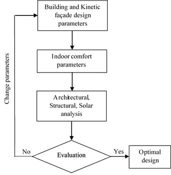
Fig. 3:Algorithmic kinetic façade design process
b) Solar analysis
The solar analysis uses the architectural data to produce 3D models with building performance analysis. The imported EPW file (for this study, the solar analysis plugin (ladybug) has been used [17]) contains weather and solar information about the building site. The analysis period of time should be defined to generate the selected sky matrix which calculates the solar radiation based on the angle of the sun at that time. The sun vector taken from the EPW file at the studied time is analysed and transformed using a basic formula to represent the movement of the kinetic shell cells around the building, so they would open and allow sunlight at a certain angle and they would close to minimize the solar radiation. This analysis helps calculate the difference in angle between each cell and the sun vector at the studied time, yet the user is able to change this ratio. Fig. 6 shows the simulation of the solar analysis in the workflow.
c) Structural analysis
In this analysis, structural edge, supporting structural braces and structural poles will be fixed to the slabs of the building in order to support the façade. The placement of these poles will be optimised according to the structural stability of the façade.
The structural analysis of the kinetic shell façade could be conducted for each side alone or could be conducted for the whole structure with the enforcement poles. Fig. 4: Cells Mechanism
Fig. 5-a: Simulation of cells of the kinetic shell façade (Grasshopper file)
Figure 5-b: Simulation of full architecture of the kinetic shell façade (Grasshopper file)
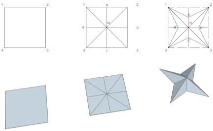
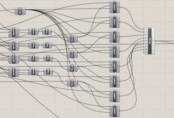
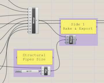
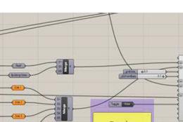
Fig. 6: Simulation of Solar Analysis (Grasshopper file)
IV CASE STUDIES Two buildings are considered as case studies in different locations around the world to ensure the effectiveness of the developed workflow model at different climate conditions. Both buildings will be redesigned as a mass only, and the radiation analysis will be conducted for three settings for each building: the building as is, the building with the kinetic square cells (option1), and the building with vertical panels (option2). The analysis is set at different times between 10:00am to 13:00pm on the 31st of December and the 21st of June.
a) Case Study 1: CUBE building
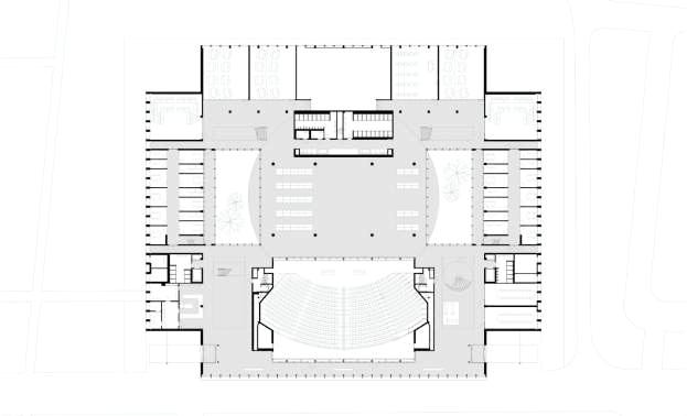
Cube is an educational building in Tilburg, Netherlands. The floor plan in Fig. 7 has an area of 11000.0 m2 and was constructed in 2018 as a part of the Tilburg University Campus. The building is symmetrical with no closed-off facades consisting of 2 floors, while the panels on the east and west side are also used as a shading device.
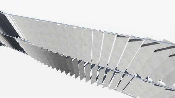
b) Case Study 2: The Vaughan Civic Centre Resource Library
The Vaughan Civic Centre Resource Library is public library in suburban Toronto, Canada. It has an area of 3306.0 m2 and was constructed in 2016. The glass and aluminum clad structure sits along a pedestrian promenade that leads to the city hall, forming a staggered and slanted pattern on the exterior. The building’s appearance changes during the day due to its sculptural shape and façade treatment. The building has a challenging design with a functional structure considering curves on all axis, as shown in Fig. 8. The northern side of the building is taken as one curve, since the program is set to design structures for 3-4 sided curvilinear buildings. Fig. 7: Cube, Tilburg, Netherlands, Floor Plan. Courtesy of http://kaanarchitecten.com
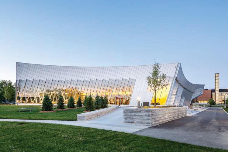
Fig. 8: Vaughan Civic Centre and Public Resource Library, Vaughan, ON, Canada. Courtesy of http://zasa.com
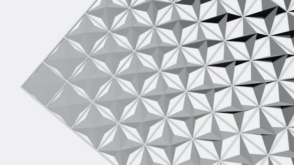
V RESULTS Option 1 analysis uses a kinetic façade designed as square cells as shown in Fig. 9-a that would open and close based on the angle of the sun vector at specific times. Each cell is estimated around 1mx1m in dimensions.
The eight surfaces inside the cell would move a maximum of 0.4m on the inner direction, while the centre point would move the exact same in the outer direction based on the normal vector on the cell itself. The movements of the kinetic shell are responsive to the sun vector at every analysis time.
Option 2 analysis uses a kinetic façade designed as vertical panels as shown in Fig. 9-b that would rotate to open and close based on the angle of the sun vector at specific times. Each panel is estimated around 1m width, and the height is based on the building’s floor height. The number of panels vertically is the number of floors and each floor has its set of panels with structural elements. The solar radiation analysis is conducted to the mass building and the movement of the panels are responsive to the sun vector at every analysis study time.
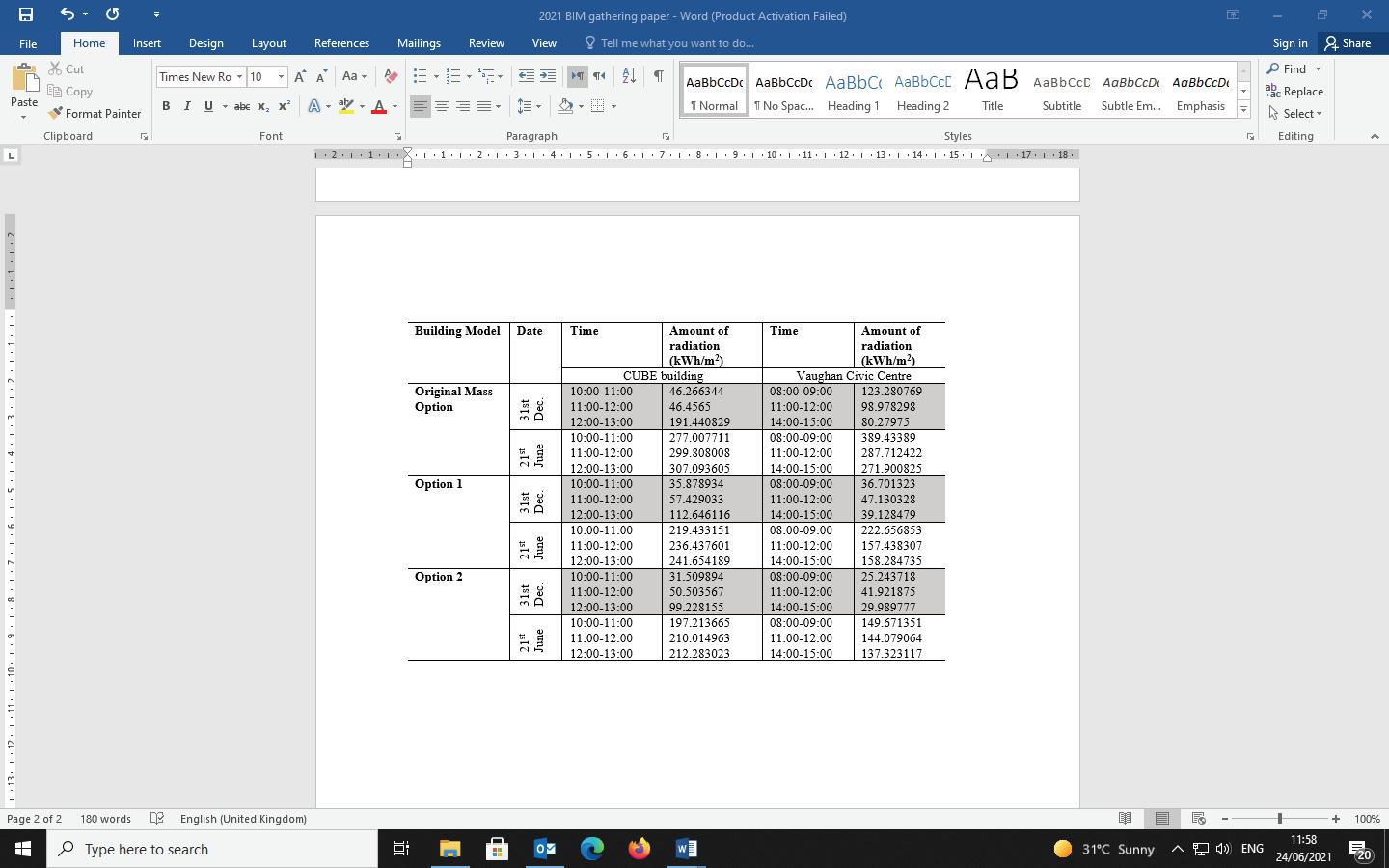
Table 2 shows the analysis results of the amount of radiation in kWh/m2 falling on the mass model. This is computed through a mass addition of results at each of the test points multiplied by the area of the face that the test point is representing.
When comparing the results for both case study buildings, it shows that option 2 provides the minimum solar radiation while keeping a good natural light ratio. The solar analysis result shows how the proposed workflow for the kinetic shell could provide sustainable design for buildings. In addition, the choice of façade systems used for the design is relatively flexible and could use solar panels for the vertical panels that can follow the sun direction based on the sun vector.
Fig. 9-a: Option 1, Cells Render
Fig. 9-b: Option 2, Vertical Panels Render
Table 2: Simulation results (Amount of radiation)
VI CONCLUSIONS This study investigated literature and existing buildings designed with kinetic shell facades. From this investigation, certain sustainability factors were defined to analyse buildings’ façade and were considered for developing a BIM parametric design workflow of kinetic shell facades. Visual programming language was used for developing this workflow. The workflow model is designed through developing a series of complex functional commands based on how the kinetic facades could work on any 4-sided curvilinear structures by importing the outline of building plans.
The workflow model has been applied on two case study buildings with curvilinear façades on four sides. The model helped in the analysis of the façade performance to reduce the solar radiation on different times during the day. Further development can improve the model functions by providing more flexible design for any building shape or choice of materials and structure.
The main outcome of the study proved the advantages of using adaptive kinetic shell structure in multiple locations and under different environmental circumstances. In addition, the developed parametric workflow can be used to design efficient architectural buildings on multiple sustainable and financial aspects.
Traditional early design stages could be changed due to the emergence of adaptive design workflows which are required to interpret and analyse conceptual designs from a building performance perspective. Incorporating visual scripting tools and algorithms enables data communication among various design tools quickly and effectively.
By leveraging this design approach, it becomes possible for designers to generate more effective solutions. This could be achieved by defining parametric values and utilising adaptive design tools to analyse and iterate optimal design solutions.
Designers are still required to evaluate design outcomes and modify the design parameters to refine the adaptive design process. Further development of this approach can utilise Artificial Intelligent techniques to analyse/refine more optimum design solutions by generating more parametric values for the design options.
REFERENCES [1] K Terzidis. Expressive Form: A Conceptual
Approach to Computational Design, London;
Spon Press, 2003. [2] W Zuk and R Clark. Kinetic Architecture, Van
Nostrand Reingold, 1970. [3] F Alotaibi. “The Role of Kinetic Envelopes to
Improve Energy Performance in Buildings”. J
Archit Eng Tech, 4:149, 2015. [4] M Rashid and C Zimring. “A review of the empirical literature on the relationships between indoor environment and stress in health care and office settings: Problems and prospects of sharing evidence” . Environment and Behavior, 40(2), 151–190, 2008. [5] C Abel. “Evolutionary Planning” . Architectural design, 563-4, December 1968. [6] TL Koglin, Movable Bridge Engineering, John
Wiley & Sons Inc., New Jersey, 2003. [7] M Fox, and M Kemp, Interactive Architecture,
Princeton Architectural Press., 2009. [8] Institut du monde arabe, https://www.imarabe.org/en/architecture,
Accessed April 26th 2021 [9] Nordische Botschaften, https://www.nordischebotschaften.org/nordicembassies-berlin, Accessed April 26th 2021. [10] City of Melbourne,. https://www.melbourne.vic.gov.au/buildingand-development/sustainable-building/councilhouse-2, Accessed April 26th 2021. [11] AHR. International Award Winning
Architectural Design Practice, AL BAHR
TOWERS, http://www.ahr-global.com/Al-
Bahr-Towers, Accessed April 26th 2021. [12] Foster + Partners https://www.fosterandpartners.com/search/?q=
Apple+store+in+Dubai+Mall, Accessed April 26th 2021.
[13] Bethany. “How Industries Use CAD:
Architecture”, Scan2CAD Website, 2017. [Online]. [14] S Krish. “A practical generative design method”. Computer-Aided Design, 43(1),.88–100, 2011. [15] J. Frazer. “Creative Design and the Generative
Evolutionary Paradigm”. In Bentley, Peter J. &
Corne, David W. (Eds.) Creative Evolutionary
Systems. Academic Press, USA, 253-274, 2001. [16] B Kolarevic. Architecture in the Digital Age:
Design and Manufacturing, Spon Press, New
York, 2003. [17] EPW LadyBug Map of World Location ladybug.tools: http://www.ladybug.tools/epwmap/
