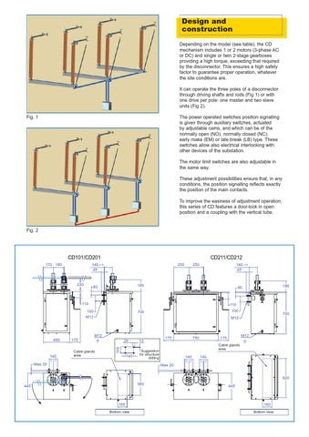
Design and construction Depending on the model (see table), the CD mechanism includes 1 or 2 motors (3-phase AC or DC) and single or twin 2-stage gearboxes providing a high torque, exceeding that required by the disconnector. This ensures a high safety factor to guarantee proper operation, whatever the site conditions are. It can operate the three poles of a disconnector through driving shafts and rods (Fig 1) or with one drive per pole: one master and two slave units (Fig 2). Fig. 1
The power operated switches position signalling is given through auxiliary switches, actuated by adjustable cams, and which can be of the normally open (NO), normally closed (NC), early make (EM) or late break (LB) type. These switches allow also electrical interlocking with other devices of the substation. The motor limit switches are also adjustable in the same way. These adjustment possibilities ensure that, in any conditions, the position signalling reflects exactly the position of the main contacts. To improve the easiness of adjustment operation, this series of CD features a door-lock in open position and a coupling with the vertical tube.
Fig. 2
CD101/CD201
CD211/CD212
140 Âą10 45
170 180
230
250
140 Âą10 45
250
195
60
110
110
100 M12
140
100
700
700
M12
M12 175 Cable glands area
26 100
450
195
60
140
= =
13
175
M12
175 Cable glands area
Suggestion for structure drilling
Max 20
750
140
140
= =
= =
Max 20 620 360
445
160 Bottom view
445
160 Bottom view