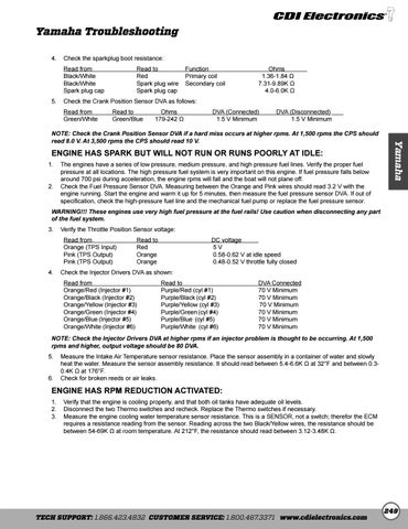
Yamaha Troubleshooting 4. Check the sparkplug boot resistance: Read from Black/White Black/White Spark plug cap
Read to Function Red Primary coil Spark plug wire Secondary coil Spark plug cap
Ohms 1.36-1.84 Ω 7.31-9.89K Ω 4.0-6.0K Ω
5. Check the Crank Position Sensor DVA as follows:
ENGINE HAS SPARK BUT WILL NOT RUN OR RUNS POORLY AT IDLE: 1. The engines have a series of low pressure, medium pressure, and high pressure fuel lines. Verify the proper fuel pressure at all locations. The high pressure fuel system is very important on this engine. If fuel pressure falls below around 700 psi during acceleration, the engine rpms will fall and the boat will not plane off. 2. Check the Fuel Pressure Sensor DVA. Measuring between the Orange and Pink wires should read 3.2 V with the engine running. Start the engine and warm it up for 5 minutes, then measure the fuel pressure sensor DVA. If out of specification, check the high-pressure fuel line and the mechanical fuel pump or replace the fuel pressure sensor.
Yamaha
Read from Read to Ohms DVA (Connected) DVA (Disconnected) Green/White Green/Blue 179-242 Ω 1.5 V Minimum 1.5 V Minimum NOTE: Check the Crank Position Sensor DVA if a hard miss occurs at higher rpms. At 1,500 rpms the CPS should read 8.0 V. At 3,500 rpms the CPS should read 10 V.
WARNING!!! These engines use very high fuel pressure at the fuel rails! Use caution when disconnecting any part of the fuel system. 3. Verify the Throttle Position Sensor voltage: Read from Orange (TPS Input) Pink (TPS Output) Pink (TPS Output)
Read to Red Orange Orange
DC voltage 5V 0.58-0.62 V at idle speed 0.48-0.52 V throttle fully closed
4. Check the Injector Drivers DVA as shown: Read from Orange/Red (Injector #1) Orange/Black (Injector #2) Orange/Yellow (Injector #3) Orange/Green (Injector #4) Orange/Blue (Injector #5) Orange/White (Injector #6)
Read to Purple/Red (cyl #1) Purple/Black (cyl #2) Purple/Yellow (cyl #3) Purple/Green (cyl #4) Purple/Blue (cyl #5) Purple/White (cyl #6)
DVA Connected 70 V Minimum 70 V Minimum 70 V Minimum 70 V Minimum 70 V Minimum 70 V Minimum
NOTE: Check the Injector Drivers DVA at higher rpms if an injector problem is thought to be occurring. At 1,500 rpms and higher, output voltage should be 80 DVA. 5. Measure the Intake Air Temperature sensor resistance. Place the sensor assembly in a container of water and slowly heat the water. Measure the sensor assembly resistance. It should read between 5.4-6.6K Ω at 32°F and between 0.30.4K Ω at 176°F. 6. Check for broken reeds or air leaks.
ENGINE HAS RPM REDUCTION ACTIVATED: 1. Verify that the engine is cooling properly, and that both oil tanks have adequate oil levels. 2. Disconnect the two Thermo switches and recheck. Replace the Thermo switches if necessary. 3. Measure the engine cooling water temperature sensor resistance. This is a SENSOR, not a switch; therefor the ECM requires a resistance reading from the sensor. Reading across the two Black/Yellow wires, the resistance should be between 54-69K Ω at room temperature. At 212°F, the resistance should read between 3.12-3.48K Ω.
TECH SUPPORT: 1.866.423.4832 CUSTOMER SERVICE: 1.800.467.3371 www.cdielectronics.com
249
