

Copyright©2018 Kobelco Construction Machinery Co.,Ltd. All rights reserved. [S2YH00011ZE10] [1115CsCshWbYs] APPLICABLE No. SK140SRLC-5 SK140SRL-5 YH08-11001~ LK08-02501~
READ, UNDERSTAND AND FOLLOW ALL SAFETY PRECAUTIONS AND INSTRUCTIONS FOUND IN THIS MANUAL BEFORE OPERATING THE MACHINE.
Book Code No. S2YH00011ZE10


Original instructions
2018.10
Destination : EUR
Copyright©2018 Kobelco Construction Machinery Co.,Ltd. All rights reserved. [S2YH00011ZE10] [1115CsCshWbYs]
Copyright©2018 Kobelco Construction Machinery Co.,Ltd. All rights reserved. [S2YH00011ZE10] [1115CsCshWbYs]
Copyright©2018 Kobelco Construction Machinery Co.,Ltd. All rights reserved. [S2YH00011ZE10] [1115CsCshWbYs] [CONTENTS] IMPORTANT INFORMATION PREFACE 0-3 STORE OPERATION & MAINTENANCE MANUALS ON THE MACHINE..............................................................0-4 SAFETY INFORMATION IN MESSAGES OR LABELS IN THIS MANUAL AND ON THE MACHINE....................0-5 SAFETY LABELS........................................................................................................................................................... 0-5 SUMMARY OF THE MACHINE.........................................................................................................................................0-7 QUALIFICATION FOR OPERATING THE MACHINE 0-8 FLUORINATED GREENHOUSE GASES 0-9 "EC" DECLARATION OF CONFORMITY 0-10 VIBRATION TO THE OPERATOR 0-12 NOISE LEVEL 0-13 CAB WITH ROPS (ROLL-OVER PROTECTIVE STRUCTURE)/FALLING OBJECTS PROTECTIVE STRUCTURE 0-14 ORDERING PARTS AND SERVICE 0-15 WARRANTY 0-16 IMPORTANT NOTIFICATION 0-17 1. SAFETY INSTRUCTIONS 1.1 SAFETY LABELS & DECALS ................................................................................................................................ 1-3 1.1.1 ALWAYS MAKE SURE ALL OF THE SAFETY LABELS ARE LEGIBLE AND NOT DAMAGED............................................................................................................................................................... 1-3 1.1.2 LOCATION OF SAFETY LABELS & DECALS.............................................................................................. 1-4 1.1.3 SAFETY LABELS 1-7 1.2 PRE-START SAFETY 1-13 1.2.1 OPERATION RULES 1-13 1.2.2 PROTECTION TOOLS 1-14 1.2.3 ABNORMAL AND EMERGENCY CONDITION 1-15 1.2.4 POTENTIAL HAZARDS WHEN OPERATING 1-16 1.2.5 FIRE PREVENTION 1-17 1.2.6 GETTING ON AND OFF THE MACHINE 1-18 1.2.7 PRE-START UP INSPECTION ON THE MACHINE 1-19 1.3 SECURE VISIBILITY 1-20 1.3.1 BE AWARE OF YOUR SURROUNDINGS.................................................................................................. 1-20 1.4 PRECAUTIONS FOR OPERATION..................................................................................................................... 1-21 1.4.1 STARTING.......................................................................................................................................................1-21 1.4.2 TRAVELING ....................................................................................................................................................1-25 1.4.3 PROHIBITED OPERATIONS 1-28 1.4.4 SAFETY CHECK ON THE PARKING MACHINE 1-35 1.5 AT THE END OF EACH SHIFT 1-36 1.6 PRECAUTIONS OF INSPECTION & MAINTENANCE 1-37 1.6.1 PERIODIC INSPECTIONS 1-37 1.6.2 BEFORE INSPECTION & MAINTENANCE 1-38 1.6.3 DURING INSPECTION & MAINTENANCE 1-39 1.6.4 PROHIBITED IN INSPECTION & MAINTENANCE 1-44 1.6.5 AFTER INSPECTION & MAINTENANCE 1-45 1.7 PRECAUTIONS FOR BATTERY 1-46 1.7.1 HANDLING THE BATTERY ...........................................................................................................................1-46 1
Copyright©2018 Kobelco Construction Machinery Co.,Ltd. All rights reserved. [S2YH00011ZE10] [1115CsCshWbYs] [
1.8 HANDLING OF THE ACCUMULATOR OR GAS SPRING 1-48 1.9 TOWING THE MACHINE 1-49 1.9.1 TOWING METHOD OF THE MACHINE 1-49 2. MACHINE FAMILIARIZATION 2.1 BASIC COMPONENTS OF THE MACHINE..........................................................................................................2-3 2.2 OPERATOR'S STATION NOMENCLATURE..........................................................................................................2-5 2.3 GAUGE CLUSTER...................................................................................................................................................2-7 2.3.1 MULTI-DISPLAY 2-8 2.3.2 ENGINE COOLANT TEMPERATURE METER 2-8 2.3.3 FUEL LEVEL METER 2-8 2.3.4 DEF/ADBLUE LEVEL GAUGE 2-9 2.3.5 HOUR METER 2-9 2.3.6 SCREEN CHANGE SWITCH 2-10 2.3.7 BUZZER STOP SWITCH 2-11 2.3.8 WORK MODE SELECT SWITCH 2-14 2.3.9 WASHER SWITCH 2-15 2.3.10 WIPER SWITCH 2-15 2.3.11 TRAVEL SPEED SELECT SWITCH 2-16 2.3.12 AUTO ACCELERATION SWITCH...............................................................................................................2-17 2.3.13 ATTACHMENT MODE SELECT SWITCH .................................................................................................2-18 2.3.14 MENU SWITCH............................................................................................................................................2-19 2.3.15 USER MENU SETTING...............................................................................................................................2-20 2.3.16 DISPLAY FOR MAINTENANCE 2-31 2.3.17 WARNING DISPLAY SCREEN 2-32 2.3.18 CLOGGING DETECTOR OF HYDRAULIC OIL FILTER 2-36 2.4 HANDLING OF SWITCHES AND METERS 2-37 2.4.1 STARTER SWITCH 2-37 2.4.2 ENGINE THROTTLE 2-37 2.4.3 WORKING LIGHT (BOOM AND DECK) 2-38 2.4.4 WORKING LIGHT SWITCH (CAB LIGHT) 2-38 2.4.5 MANUAL REGENERATION SWITCH 2-38 2.4.6 PRESSURE RELEASE SWITCH..................................................................................................................2-39 2.4.7 OVERLOAD ALARM SELECT SWITCH 2-39 2.4.8 CAB ROTATING LIGHT SWITCH..................................................................................................................2-40 2.4.9 QUICK HITCH OPERATION SWITCH..........................................................................................................2-40 2.4.10 CAP (OPTION SWITCH).............................................................................................................................2-41 2.4.11 HORN SWITCH.............................................................................................................................................2-41 2.4.12 ENGINE THROTTLE FOR REDUNDANT MODE 2-42 2.4.13 SWING PARKING BRAKE RELEASE SWITCH 2-43 2.4.14 KPSS RELEASE SWITCH 2-43 2.4.15 ENGINE STOP SWITCH 2-44 2.4.16 12 V POWER SUPPLY 2-44 2.4.17 USB PORT/EXTERNAL INPUT TERMINAL (AUX) 2-45 2.5 HANDLING OF LEVERS AND PEDALS 2-46 2.5.1 LOCATION OF LEVERS AND PEDALS 2-46 2
CONTENTS]
Copyright©2018 Kobelco Construction Machinery Co.,Ltd. All rights reserved. [S2YH00011ZE10] [1115CsCshWbYs] [CONTENTS] 2.5.2 Pilot Control Shut-Off Lever. 2-47 2.5.3 OPERATOR CONTROL LEVERS 2-48 2.5.4 TRAVEL LEVER & PEDAL 2-49 2.6 HANDLING OF FUSE & RELAY BOX 2-50 2.6.1 ABOUT FUSE & RELAY BOX 2-50 2.6.2 REPLACING FUSES 2-50 2.6.3 FUSE CAPACITY AND CIRCUIT NAME ......................................................................................................2-51 2.7 HANDLING OF FUSIBLE LINK (FOR STARTER).............................................................................................2-52 2.7.1 FUSIBLE LINK INSPECTION/REPLACEMENT......................................................................................... 2-52 2.8 CONTROLLER 2-53 2.9 DUAL MONITOR 2-54 2.9.1 NAME OF EACH PART 2-54 2.9.2 MENU SCREEN 2-54 2.9.3 MAIN MENU 2-55 2.9.4 PICTURE ADJUSTMENT (PICTURE) 2-55 2.9.5 SETTING OF CAMERA RELATED ITEMS (CAMERA) 2-56 2.9.6 SWITCHING OF DIMMER (LIGHT ADJUSTMENT) (DIMMER) 2-57 2.10 HANDLING OF RADIO 2-58 2.10.1 NAME OF EACH PART 2-58 2.10.2 RECEIVABLE FREQUENCY 2-59 2.10.3 SOURCE ON 2-59 2.10.4 SWITCHING SOURCE................................................................................................................................2-60 2.10.5 FM/AM............................................................................................................................................................2-61 2.10.6 USB AUDIO...................................................................................................................................................2-64 2.10.7 BLUETOOTH AUDIO 2-69 2.10.8 AUX................................................................................................................................................................2-70 2.10.9 CLOCK DISPLAY 2-70 2.10.10 VOLUME CONTROL 2-71 2.10.11 DISPLAY CHANGE 2-72 2.10.12 MENU 2-74 2.10.13 BLUETOOTH AUDIO FUNCTION, AND USB PORT/EXTERNAL INPUT TERMINAL 2-82 2.10.14 DESCRIPTION OF BUILT-IN WIRELESS EQUIPMENT 2-83 2.11 AIR CONDITIONER 2-91 2.11.1 GRILLE (AIR OUTLET) 2-91 2.11.2 AIR CONDITIONER CONTROL PANEL 2-92 2.11.3 AIR CONDITIONER OPERATION PANEL 2-93 2.11.4 HOW TO USE AIR CONDITIONER............................................................................................................2-96 2.11.5 SELF-DIAGNOSIS FUNCTION IN DISPLAY MONITOR..........................................................................2-98 2.11.6 HANDLING AT IN-SEASON/OFF-SEASON. ............................................................................................. 2-99 2.12 HANDLING OF SEAT BELT 2-100 2.12.1 HOW TO FASTEN SEAT BELT. 2-100 2.12.2 HOW TO UNFASTEN SEAT BELT 2-100 2.13 HANDLING OF OPERATOR'S SEAT 2-101 2.13.1 HEIGHT AND TILT ADJUSTMENT 2-101 2.13.2 RECLINING ADJUSTMENT 2-102 2.13.3 FRONT/REAR SEAT ADJUSTMENT 2-102 2.13.4 ARM REST ADJUSTMENT 2-102 3
3. MACHINE OPERATION
Copyright©2018 Kobelco Construction Machinery Co.,Ltd. All rights reserved. [S2YH00011ZE10] [1115CsCshWbYs] [CONTENTS] 2.13.5 HEAD REST ADJUSTMENT 2-102 2.13.6 ADJUSTING AIR SUSPENSION 2-102 2.13.7 SEAT HEATER (OPTION) 2-102 2.13.8 LUMBAR SUPPORT 2-102 2.14 HANDLING OF OPERATOR'S SEAT 2-103 2.14.1 DAMPER ADJUSTMENT 2-103 2.14.2 WEIGHT ADJUSTMENT............................................................................................................................2-104 2.14.3 HEIGHT ADJUSTMENT. ...........................................................................................................................2-104 2.14.4 RECLINING ADJUSTMENT......................................................................................................................2-105 2.14.5 FRONT/REAR ADJUSTMENT OF SEAT 2-105 2.14.6 TILT ADJUSTMENT OF SEAT SEATING SURFACE 2-105 2.14.7 FRONT/REAR ADJUSTMENT OF SEAT SEATING SURFACE 2-105 2.14.8 ARM REST ADJUSTMENT 2-105 2.14.9 HEAD REST ADJUSTMENT 2-105 2.14.10 SEAT HEATER 2-106 2.14.11 LUMBAR SUPPORT 2-106 2.15 HANDLING PARTS INSIDE CAB 2-107 2.15.1 CAB DOOR LOCK. 2-107 2.15.2 OPENING DOOR FROM INSIDE OF CAB 2-107 2.15.3 OPENING/CLOSING FRONT WINDOW (UPPER). 2-108 2.15.4 RETRACTING FRONT WINDOW (LOWER) 2-109 2.15.5 CAB ROOM LAMP......................................................................................................................................2-109 2.16 EMERGENCY ESCAPE FROM OPERATOR'S STATION............................................................................ 2-110 2.17 OTHER ACCESSORIES....................................................................................................................................2-111 2.17.1 TOOL BOX 2-111 2.17.2 GREASE GUN HOLDER............................................................................................................................2-111 2.17.3 CUP HOLDER 2-111 2.17.4 GUARD/SIDE DOOR (WITH LOCK) 2-112 2.18 BATTERY POWER-OFF SWITCH 2-114 2.19 FUEL SUPPLY PUMP. 2-115
3.1 EVERYDAY CHECK-UP 3-3 3.2 CHECK BEFORE STARTING ENGINE 3-4 3.2.1 CHECKING COOLANT LEVEL AND REFILLING.......................................................................................... 3-4 3.2.2 CHECKING ENGINE OIL LEVEL OF ENGINE OIL PAN AND REFILLING ...............................................3-5 3.2.3 CHECKING FUEL LEVEL AND REFUELING................................................................................................3-7 3.2.4 DRAINING FUEL PRE-FILTER........................................................................................................................3-8 3.2.5 CHECKING OIL LEVEL OF HYDRAULIC OIL TANK 3-9 3.2.6 CHECKING FAN BELT AND AIR CONDITIONING COMPRESSOR BELT 3-10 3.2.7 CHECKING RADIATOR, OIL COOLER AND FILTER 3-11 3.2.8 CHECKING DEF/ADBLUE LEVEL AND REFILLING 3-11 3.2.9 ADJUSTMENT OF OPERATOR'S SEAT 3-12 3.2.10 ADJUSTMENT OF MIRRORS 3-13 3.2.11 CHECKING MULTI-DISPLAY 3-16 3.2.12 CHECKING WORKING LIGHT 3-16 4
Copyright©2018 Kobelco Construction Machinery Co.,Ltd. All rights reserved. [S2YH00011ZE10] [1115CsCshWbYs] [CONTENTS] 3.2.13 CHECKING OF AIR CLEANER INLET 3-16 3.3 STARTING ENGINE 3-17 3.3.1 START-UP UNDER NORMAL TEMPERATURE CONDITIONS 3-17 3.3.2 START UP IN COLD CONDITIONS 3-19 3.3.3 USING JUMPER CABLES 3-20 3.4 STOPPING MACHINE ENGINE 3-22 3.5 CHECK AFTER STARTING ENGINE...................................................................................................................3-23 3.5.1 CHECK OF PILOT CONTROL SHUT-OFF LEVER ...................................................................................3-23 3.5.2 CHECK OF ENGINE AND MULTI-DISPLAY............................................................................................... 3-24 3.6 WARMING-UP 3-25 3.6.1 ENGINE WARMING-UP 3-25 3.6.2 WARMING-UP HYDRAULIC OIL 3-26 3.7 AUTO IDLING STOP FUNCTION 3-27 3.7.1 RESTART AFTER AUTO IDLE STOP 3-27 3.8 SELECTION OF WORK MODE 3-28 3.9 SWITCHING ATTACHMENT MODE 3-29 3.10 MACHINE OPERATION 3-30 3.10.1 PRECAUTIONS OF MACHINE OPERATION 3-30 3.10.2 TRAVEL PROCEDURES 3-31 3.10.3 CHANGING TRAVEL SPEED (1ST AND 2ND) 3-33 3.10.4 MACHINE OPERATION IN WATER OR ON SOFT GROUND 3-34 3.10.5 GETTING OUT OF SOFT GROUND......................................................................................................... 3-35 3.10.6 SWING AND ATTACHMENT/EQUIPMENT OPERATIONS..................................................................... 3-36 3.11 WORK PROCEDURES OF MACHINE .............................................................................................................. 3-39 3.11.1 DIGGING WORK 3-39 3.11.2 LOADING WORK...........................................................................................................................................3-39 3.12 ALWAYS PARK MACHINE PROPERLY 3-40 3.12.1 PARKING MACHINE ON SLOPE 3-40 3.13 INSPECTION AND CHECK AFTER OPERATION. 3-41 3.14 MACHINE OPERATION IN ADVERSE CONDITIONS 3-42 3.14.1 OPERATION IN COLD CONDITION 3-42 3.14.2 OPERATION AT SEASHORE. 3-43 3.14.3 OPERATION IN SANDY AND DUSTY AREAS 3-43 3.15 PRECAUTIONS FOR LONG-TERM STORAGE 3-44 3.15.1 WASHING MACHINE 3-44 3.15.2 REFILLING OIL/GREASING 3-44 3.15.3 BATTERY......................................................................................................................................................3-44 3.15.4 COOLANT.....................................................................................................................................................3-44 3.15.5 PREVENTION OF DUST AND MOISTURE...............................................................................................3-45 3.15.6 PERIODICAL LUBRICATING OPERATION (DURING STORAGE) 3-45 3.15.7 TREATMENT AFTER LONG-TERM STORAGE 3-45 4. INSPECTION AND MAINTENANCE 4.1 GENERAL 4-3 4.2 INSPECTING AND MAINTAING MACHINE. 4-4 4.2.1 PERIODIC INSPECTION AND MAINTENANCE 4-4 5
Copyright©2018 Kobelco Construction Machinery Co.,Ltd. All rights reserved. [S2YH00011ZE10] [1115CsCshWbYs] [CONTENTS] 4.2.2 PRECAUTIONS OF INSPECTION AND MAINTENANCE 4-5 4.3 EXHAUST GAS CLEANING DEVICE 4-6 4.3.1 ABOUT EXHAUST GAS CLEANING DEVICE 4-6 4.3.2 ABOUT AUTOMATIC REGENERATION 4-6 4.3.3 ABOUT MANUAL REGENERATION. 4-7 4.3.4 INSPECTION AND MAINTENANCE 4-8 4.3.5 PRECAUTIONS OF USING EXHAUST GAS CLEANING DEVICE............................................................ 4-8 4.4 SCR SYSTEM AND DEF/ADBLUE ........................................................................................................................4-9 4.4.1 SCR.....................................................................................................................................................................4-9 4.4.2 DEF/AdBlue 4-9 4.4.3 DEF/AdBlue CIRCUIT AND BATTERY 4-9 4.4.4 STORING DEF/ADBLUE 4-9 4.4.5 PURCHASING DEF/ADBLUE 4-9 4.4.6 LOW DEF/ADBLUE LEVEL 4-10 4.4.7 QUALITY PROBLEMS OF DEF/ADBLUE 4-10 4.4.8 DRAINING DEF/ADBLUE 4-11 4.4.9 FAILURE OF EXHAUST GAS CLEANING DEVICE 4-12 4.4.10 EMERGENCY EVACUATION MODE 4-13 4.4.11 SCR INSPECTION AND MAINTENANCE 4-13 4.5 LUBRICANT, FUEL & COOLANT SPECIFICATIONS 4-14 4.6 ABOUT USE OF BIO-OIL (BIODEGRADABLE HYDRAULIC OIL). 4-16 4.6.1 GREASE AND OIL FOR USE.......................................................................................................................4-16 4.6.2 PRECAUTIONS FOR BIO-OIL......................................................................................................................4-16 4.6.3 REPLACEMENT INTERVAL OF BIO-OIL....................................................................................................4-16 4.6.4 FLUSHING PROCEDURES OF BIO-OIL 4-16 4.7 MAINTENANCE PARTS.......................................................................................................................................4-17 4.8 TIGHTENING TORQUES FOR BOLTS & NUTS (SPECIFIC POSITIONS) 4-18 4.9 TIGHTENING TORQUES FOR BOLTS & NUTS 4-20 4.10 TIGHTENING TORQUES FOR JOINTS & HYDRAULIC HOSES 4-22 4.11 INSPECTION AND MAINTENANCE CHART 4-24 4.12 MAINTENANCE WHEN REQUIRED. 4-29 4.12.1 CHECKING AND REPLACING WIPER BLADES 4-29 4.12.2 WASHER FLUID INSPECTION 4-29 4.12.3 REPLACING BUCKET. 4-30 4.12.4 REPLACING TOOTH POINT AND SIDE CUTTER 4-32 4.12.5 INSPECTION AND ADJUSTMENT OF BUCKET GAP ADJUSTMENT MECHANISM 4-35 4.12.6 BLEEDING AIR FROM FUEL PIPING.......................................................................................................4-36 4.12.7 RELEASING INTERNAL PRESSURE IN HYDRAULIC SYSTEM..........................................................4-37 4.13 8 HOUR (DAILY) INSPECTION & MAINTENANCE PROCEDURES ...........................................................4-38 4.13.1 GREASING ATTACHMENT 4-38 4.14 50 HOUR INSPECTION & MAINTENANCE PROCEDURES 4-40 4.14.1 INSPECTING AND MAINTAINING BATTERY. 4-40 4.14.2 DRAINING WATER AND SEDIMENT IN FUEL TANK 4-43 4.14.3 ADJUSTING CRAWLER TENSION 4-44 4.15 120 HOUR INSPECTION & MAINTENANCE PROCEDURES 4-46 4.15.1 CHECKING ENGINE OIL LEVEL OF SWING REDUCTION UNIT 4-46 4.15.2 CHECKING OIL LEVEL OF TRAVEL REDUCTION UNIT 4-47 6
Copyright©2018 Kobelco Construction Machinery Co.,Ltd. All rights reserved. [S2YH00011ZE10] [1115CsCshWbYs] [CONTENTS] 4.16 250 HOUR (3-MONTH) INSPECTION & MAINTENANCE PROCEDURES 4-48 4.16.1 ADJUSTING FAN BELT AND AIR CONDITIONING COMPRESSOR BELT 4-48 4.16.2 CHECKING INTAKE SYSTEM RUBBER HOSE 4-51 4.16.3 CHECKING RADIATOR HOSES 4-52 4.16.4 CLEANING OR REPLACING AIR CONDITIONER FILTERS 4-54 4.16.5 INSPECTING, CLEANING, OR REPLACING AIR CLEANER ELEMENT 4-56 4.16.6 CLEANING OR REPLACING RADIATOR CAP.........................................................................................4-58 4.16.7 INSPECTING SCR SYSTEM....................................................................................................................... 4-58 4.16.8 CLEANING RADIATOR, OIL COOLER CORE AND FILTER ..................................................................4-59 4.17 500 HOUR (6-MONTH) INSPECTION & MAINTENANCE PROCEDURES 4-61 4.17.1 REPLACING ENGINE OIL AND ENGINE OIL FILTER 4-61 4.17.2 REPLACING FUEL PRE-FILTER 4-64 4.17.3 REPLACING FUEL FILTER 4-65 4.17.4 GREASING SWING BEARING 4-66 4.17.5 CHECKING SWING BEARING MOUNTING BOLT FOR LOOSENESS 4-66 4.17.6 CLEANING FUEL TANK CAP AND STRAINER 4-67 4.17.7 LUBRICATING PUSH ROD OF CONTROL LEVER 4-68 4.17.8 CHECKING AIR CONDITIONER REFRIGERANT 4-69 4.17.9 CLEANING OR REPLACING ELECTROMAGNETIC FUEL PUMP 4-71 4.18 1000 HOUR (12-MONTH) INSPECTION & MAINTENANCE PROCEDURES 4-73 4.18.1 REPLACING RETURN FILTER 4-73 4.18.2 REPLACING AIR BREATHER ELEMENT..................................................................................................4-75 4.18.3 CHECKING ENGINE MOUNTING BRACKET FOR TIGHTENING CONDITION..................................4-76 4.18.4 CHECKING BATTERY VOLTAGE. .............................................................................................................4-77 4.19 2000 HOUR INSPECTION & MAINTENANCE PROCEDURES 4-78 4.19.1 REPLACING COOLANT..............................................................................................................................4-78 4.19.2 REPLACING OIL IN SWING REDUCTION UNIT 4-80 4.19.3 REPLACING OIL IN TRAVEL REDUCTION UNITS 4-81 4.19.4 CLEANING SUCTION STRAINER 4-82 4.19.5 GREASING SWING REDUCTION UNIT 4-83 4.19.6 CHECKING GREASE IN SWING GREASE BATH 4-84 4.19.7 CLEANING PILOT LINE FILTER 4-85 4.20 5000 HOUR INSPECTION & MAINTENANCE PROCEDURES 4-86 4.20.1 REPLACING HYDRAULIC OIL 4-86 4.20.2 REPLACING DEF/AdBlue SUPPLY MODULE FILTER 4-89 5. TRANSPORTATION 5.1 TRANSPORTATION.................................................................................................................................................5-3 5.1.1 STRICTLY OBSERVE TRANSPORTATION RELATED REGULATIONS 5-3 5.2 LOADING/UNLOADING THE MACHINE 5-5 5.2.1 LOADING 5-6 5.2.2 FIXING THE MACHINE 5-8 5.2.3 UNLOADING 5-9 5.3 MACHINE LIFTING 5-10 5.3.1 THE POSITION OF THE LIFTED MACHINE 5-10 5.4 INSTALLING AND REMOVING MIRROR 5-11 7
Copyright©2018 Kobelco Construction Machinery Co.,Ltd. All rights reserved. [S2YH00011ZE10] [1115CsCshWbYs]
6. SPECIFICATION 6.1 GENERAL SPECIFICATIONS 6-3 6.1.1 SK140SRLC-5, SK140SRL-5 6-3 6.2 SHOE TYPES AND USES 6-4 6.2.1 SK140SRLC-5 6-4 6.2.2 SK140SRL-5. 6-5 6.3 WORKING RANGES 6-6 6.3.1 BACKHOE ATTACHMENT (SK140SRLC-5)..................................................................................................6-6 6.3.2 BACKHOE ATTACHMENT (SK140SRL-5) 6-7 6.4 ATTACHMENT TYPE AND COMBINATION...........................................................................................................6-8 6.4.1 FRONT ATTACHMENT VARIATION................................................................................................................6-8 6.5 LIFTING CAPACITY.................................................................................................................................................6-9 6.5.1 SK140SRLC-5:4.68m (15'4") BOOM 6-9 6.5.2 SK140SRLC-5:4.68m (15'4") BOOM 6-10 6.5.3 SK140SRL-5:4.68m (15'4") BOOM 6-11 7. MACHINE OPERATION MANAGEMENT SYSTEM 7.1 MACHINE OPERATION MANAGEMENT SYSTEM 7-3 7.2 REMOTE DOWNLOAD SYSTEM 7-4 7.3 DESCRIPTION OF BUILT-IN WIRELESS EQUIPMENT 7-6 8. OPTIONAL EQUIPMENT 8.1 OPERATION OF HYDRAULIC BREAKER AND NIBBLER (CRUSHER) ...........................................................8-3 8.1.1 DO NOT USE FOR DEMOLITION OPERATION...........................................................................................8-3 8.1.2 SELECTION OF HYDRAULIC BREAKER AND NIBBLER (CRUSHER) 8-3 8.1.3 BEFORE OPERATING HYDRAULIC BREAKER 8-3 8.1.4 PRECAUTIONS FOR IMPURITY AND HYDRAULIC OIL 8-3 8.1.5 PRECAUTIONS IN USE OF BREAKER 8-3 8.1.6 PRECAUTIONS IN USE OF NIBBLER (CRUSHER) 8-9 8.2 SELECTION OF ATTACHMENT MODE AND SELECTOR VALVE 8-14 8.2.1 SELECTION OF ATTACHMENT MODE 8-14 8.2.2 SWITCHING SELECTOR VALVE 8-16 8.3 SWITCHING STOP VALVE 8-17 8.4 FLOW RATE ADJUSTMENT 8-18 8.5 CONTROL OF PROPORTIONAL HAND CONTROL EXTRA, NIBBLER (CRUSHER), BREAKER...................................................................................................................................................................8-19 8.5.1 EXTRA HAND CONTROL.............................................................................................................................8-20 8.5.2 HORN SWITCH ..............................................................................................................................................8-20 8.5.3 NIBBLER (CRUSHER) OPERATION 8-20 8.5.4 BREAKER OPERATION 8-21 8.6 CONTROL OF PROPORTIONAL HAND CONTROL NIBBLER (CRUSHER), BREAKER 8-22 8.6.1 HORN SWITCH 8-23 8.6.2 NIBBLER OPERATION 8-23 8.6.3 BREAKER OPERATION 8-24 8.7 PERIODIC INSPECTION AND MAINTENANCE OF NIBBLER (CRUSHER) AND BREAKER 8-25 8
[CONTENTS]
9. SPECIAL PROCEDURES
Copyright©2018 Kobelco Construction Machinery Co.,Ltd. All rights reserved. [S2YH00011ZE10] [1115CsCshWbYs] [CONTENTS] 8.7.1 PERIODIC INSPECTION AND MAINTENANCE CHART OF NIBBLER (CRUSHER) AND BREAKER 8-25 8.7.2 REINFORCEMENT OF ATTACHMENT. 8-25 8.8 PRECAUTIONS FROM BREAKER MANUFACTURERS 8-26 8.8.1 INSTALL HIGH- AND LOW-PRESSURE ACCUMULATORS 8-26 8.8.2 ACCUMULATOR INSTALLATION CRITERIA 8-26 8.8.3 INSTALL RELIEF VALVE ...............................................................................................................................8-27 8.9 OBJECT HANDLING.............................................................................................................................................8-28 8.9.1 SAFETY PRECAUTIONS..............................................................................................................................8-28 8.9.2 LIFTING WORK 8-29 8.9.3 RATED LIFT CAPACITY CHART 8-31 8.10 QUICK HITCH 8-32 8.10.1 PROHIBITED WORKS 8-32 8.10.2 PRECAUTIONS FOR USE 8-33 8.10.3 REMOVING FRONT ATTACHMENT 8-34 8.10.4 INSTALLING FRONT ATTACHMENT 8-35 8.10.5 MANUAL SWITCHING OF PRESSURE REDUCING VALVE FOR QUICK HITCH 8-36 8.11 TRAVEL ALARM SWITCH 8-37
9.1 SPECIAL PROCEDURES AT ENGINE FAILURE.................................................................................................9-3 9.2 LOWERING ATTACHMENT TO GROUND ............................................................................................................9-4 9.3 RELEASING TRAVEL MOTOR BRAKES.............................................................................................................. 9-5 9.4 RELEASING SWING BRAKES. 9-8 9.4.1 SWING BRAKE RELEASE PROCEDURE WITH HYDRAULIC HAND PUMP 9-8 9.4.2 SWING BRAKE RELEASE PROCEDURE BY DISASSEMBLY 9-10 9
Copyright©2018 Kobelco Construction Machinery Co.,Ltd. All rights reserved. [S2YH00011ZE10] [1115CsCshWbYs] [CONTENTS]
Copyright©2018 Kobelco Construction Machinery Co.,Ltd. All rights reserved. [S2YH00011ZE10] [1115CsCshWbYs] 10
Copyright©2018 Kobelco Construction Machinery Co.,Ltd. All rights reserved. [S2YH00011ZE10] [1115CsCshWbYs] [IMPORTANT INFORMATION] IMPORTANT INFORMATION 0-1
Copyright©2018 Kobelco Construction Machinery Co.,Ltd. All rights reserved. [S2YH00011ZE10] [1115CsCshWbYs] [IMPORTANT INFORMATION]
Copyright©2018 Kobelco Construction Machinery Co.,Ltd. All rights reserved. [S2YH00011ZE10] [1115CsCshWbYs] 0-2
PREFACE
• Read, understand and follow the safety messages and instructions in this manual and the safety messages on the machine. If these safety messages are not followed, serious injury or death could occur.
• Always be aware of your surroundings when operating this machine and understand the capabilities of this machine and the attachment/equipment.
• Always use caution to safely operate this machine.
Use of this product and this manual
• Improper operation, maintenance or repair of this machine may cause serious injury, death or damage to the machine.
• Do not operate this machine for the first time or perform any inspection, maintenance or repair on this machine, until you have carefully read and understand the operation, inspection, maintenance, and repair information in this manual.
– Operation related activities include setting up, rectifying malfunctions and the disposal of materials.
– Maintenance related activities include lubrication, maintenance, inspection and repair work.
– Transportation related activities include loading and unloading the machine.
• For machines equipped with a specialized attachment, read the section related to the specialized attachment in this manual and any additional manuals for the specialized attachment.
• If this manual is lost, damaged or unreadable, order a replacement from your KOBELCO authorized dealer.
• This manual is a part of this machine and should be transferred with the machine to new users or owners.
• Always use genuine KOBELCO parts. Do not use aftermarket or non-KOBELCO parts on your machine.
• Manufacturers cannot anticipate every possible scenario and potential hazard that may arise during operation, inspection and maintenance activities. Therefore, the warnings in this manual and on the product may not communicate all of the possible safety precautions for your situation. When performing any operation, inspection and maintenance activities that are not contained in this manual, proceed at your own risk and do not perform any unsafe acts. You should also ensure the machine will not be damaged or create an unsafe condition by your actions. Always follow the safety procedures in this manual and for your worksite. Never perform any task or operation prohibited by this manual.
• If a tool, procedure, work method or operating technique not specifically recommended by KOBELCO is used, you must evaluate that it is safe for yourself and others to proceed. You should also ensure the machine will not be damaged or create an unsafe condition by the operation, maintenance and/or repair procedures you choose. Never perform any task or operation prohibited by this manual.
• The information, specification, and illustrations in this manual are based on information available at the time it was written. KOBELCO may change the specifications, torques, pressures, measurements, adjustments, illustrations, and other content at anytime without any obligation to notify the users/owners of these changes. Your KOBELCO authorized dealer will have the most current information available.
• Should there be questions, errors, omissions or other issues that need to be communicated to the manufacturer, contact your KOBELCO authorized dealer.
• KOBELCO provides machines produced in accordance with regulations and standards of a country in which the machine is sold to the first owner. If you have a machine purchased in a foreign country or from a person or company in another country, your machine may lack safety devices or machine components or not meet a safety standard required in your country. Please contact your KOBELCO authorized dealer to ask whether your machine's specifications meet the regulations and the standards in your country.
Copyright©2018 Kobelco Construction Machinery Co.,Ltd. All rights reserved. [S2YH00011ZE10] [1115CsCshWbYs]
[IMPORTANT INFORMATION]
0-3
The copyright of this manual belongs to KOBELCO CONSTRUCTION MACHINERY CO., LTD. Copy, reproduction, distribution, and delivery (including these actions on the Internet) of all or part of this manual are prohibited without permission of KOBELCO CONSTRUCTION MACHINERY CO., LTD.
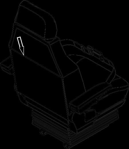
STORE OPERATION & MAINTENANCE MANUALS ON THE MACHINE
Always store all manuals for this machine and any attachments, including this manual and the related manuals, in the pocket located at the rear side of the operator's seat. Check the manuals are in this location as a part of your pre-start inspection. If the manuals are not present during your pre-start inspection, inform your supervisor and order replacement manuals from your KOBELCO authorized dealer.
Copyright©2018 Kobelco Construction Machinery Co.,Ltd. All rights reserved. [S2YH00011ZE10] [1115CsCshWbYs] [IMPORTANT INFORMATION]
0-4
SAFETY INFORMATION IN MESSAGES OR LABELS IN THIS MANUAL AND ON THE MACHINE
Many accidents are the result of not following basic safety precautions and could have been avoided by recognizing potentially hazardous situations.
Proper risk assessment can prevent many accidents from occurring. During operation, always pay attention to the potential hazards near the machine and at your worksite.
• Improper operation, inspection, maintenance and repair could cause serious injury, death or property damage. Before operating, inspecting and maintaining this machine, carefully read and understand this manual, the related manuals, and any attachment manuals that may be provided to you.
• Only allow trained and experienced personnel to operate, to inspect and to maintain this machine. These individuals must also comply with all applicable employment, industry, and governmental rules, standards, and regulations.
Many safety messages in this manual or on the labels on this machine contain signal words. Signal words are used to identify safety messages and property damage messages and designate a level of hazard seriousness. Many of these safety messages may also contain avoidance information.
This safety alert symbol identifies important safety messages in this manual. When you see this symbol, be alert, your safety is involved, carefully read the message that follows, and inform other operators.
The three signal words are DANGER, WARNING and CAUTION. Each alerts the viewer to the existence and relative seriousness of a hazard. They are reserved for personal injury hazards. Safety signs identified by DANGER shall be used sparingly and only for those situations presenting the most serious hazards. Hazards identified by WARNING present a lesser degree of risk of injury or death than those identified by DANGER.
DANGER indicates a hazard with a high level of risk which, if not avoided, will result in death or serious injury.

WARNING indicates a hazard with a medium level of risk which, if not avoided, could result in death or serious injury.
CAUTION indicates a hazard with a low level of risk which, if not avoided, could result in minor or moderate injury.
Other than the above-mentioned signal words, the following words identify important information which must be kept for the protection of the machine and may be helpful for the operator.
Notice indicates information considered important, but not hazard related (e.g., messages related to property damage)
Note indicates information that may be helpful for the operator.
SAFETY LABELS
Safety labels are affixed to machine to alert the operator and surrounding personnel of hazardous situations during operation, inspection or maintenance. There are two types of "safety labels" on this machine. One is "SAFETY LABEL INCLUDING SIGNALWORDS" and the other is "PICTORIAL ONLY SAFETY LABELS".
Copyright©2018 Kobelco Construction Machinery Co.,Ltd. All rights reserved. [S2YH00011ZE10] [1115CsCshWbYs] [IMPORTANT INFORMATION]
0-5
Example of the safety label including signal words
Example of a pictorial only safety label

The pictorial only safety label is used to alert the operator and surrounding personnel of potentially hazardous situations. For pictorial only safety label, the hazard pictorial is in the upper or left box, and the avoidance information is in the lower or right box.

Copyright©2018 Kobelco Construction Machinery Co.,Ltd. All rights reserved. [S2YH00011ZE10] [1115CsCshWbYs] [IMPORTANT INFORMATION]
0-6
ZL11M02708
SUMMARY OF THE MACHINE
APPLICABLE WORKS
Use this machine in the following applications:
• Digging
• Trenching
• Loading
• Leveling
• Demolishing
Never use the machine for any purpose other than the above applications. For details of work procedures, please refer to "MACHINE OPERATION" in Chapter 3 and "OPTIONAL EQUIPMENT" in Chapter 8.
FRONT, REAR, RIGHT & LEFT OF THE MACHINE

This manual refers to the front, rear, right & left of this machine as seen when sitting in the operator's seat with the machine in the normal travel position. The normal travel position is when the idler wheels are positioned at the front under the cab and the drive sprockets are positioned at the rear.

BREAK-IN OPERATION
Prior to shipment, this machine was inspected and adjusted by KOBELCO. Future performance and service life of this machine depends on how the machine is operated during the break-in period.
During the break-in period
• Always sufficiently warm-up the engine and the hydraulic oil.
• Do not operate with loads that exceed the recommended load status for each phase shown in the table or operate at high speeds.
• Do not perform a sudden start, sudden acceleration, or other sudden changes in engine speed.

• Avoid unnecessary sudden stops or sudden changes in driving direction.
• Do not operate the engine at high speed for extended periods of time.
Operating with heavy loads during the first 100 hours of operation may significantly affect the performance and the life of the machine. Use extreme caution if operating with heavy loads during the break-in period.
Copyright©2018 Kobelco Construction Machinery Co.,Ltd. All rights reserved. [S2YH00011ZE10] [1115CsCshWbYs] [IMPORTANT INFORMATION]
Hour Meter Load Status Less than 10 hours About 60% Less than 100 hours About 80% 100 hours and more Full load
0-7
QUALIFICATION FOR OPERATING THE MACHINE
If a license or other special qualification is required to operate a hydraulic excavator in the country where this machine will be operated, all operators of this machine must meet those requirements and have a valid (not expired) license or qualification.
Copyright©2018 Kobelco Construction Machinery Co.,Ltd. All rights reserved. [S2YH00011ZE10] [1115CsCshWbYs] [IMPORTANT INFORMATION]
0-8
FLUORINATED GREENHOUSE GASES
REGULATION (EU) No 517/2014 OF THE EUROPEAN PARLIAMENTAND OF THE COUNCIL of 16 April 2014 on fluorinated greenhouse gases and repealing Regulation (EC) No 842/2006
Contains fluorinated greenhouse gases.
Copyright©2018 Kobelco Construction Machinery Co.,Ltd. All rights reserved.
[S2YH00011ZE10] [1115CsCshWbYs]
[IMPORTANT INFORMATION]
TYPE OF F GAS HFC-134a TOTAL F GAS MASS (kg) 0.8 TOTAL EQ(CO2) (t) 1.2 GWP (Global warming potential) 1,430 0-9
"EC" DECLARATION OF CONFORMITY
On the following pages, a facsimile copy of the "EC" Declaration of Conformity (EC DoC) is provided. The EC DoC is the manufacturer's declaration about equipment compliance to relevant EU provisions.
Please keep the original document in a safe place. Local authorities may require you to show this document in order to assure compliance of your equipment.
IMPORTANT: an original of this "EC" declaration is supplied with each machine and must be kept carefully by the owner.
IMPORTANT: the official documents supplied with the machine must be kept by the owner so as to be able to present them to any inspecting authority which may request them.
• Under point 1.2 those options or variants are listed which have safety related functions. Some of them are standard provided, like the falling objects protective structure and the roll-over protective structure (please refer to the next page for other detail).
Others, like object handling kit required to lift loose objects, are available upon Customer request. Please address to your KOBELCO authorized dealer to know the availability of variants/optionals provided for your machine.
• Under point 2 all information required by EU "Outdoor Noise" Directive 2000/14/EC is given. Please refer to your own original EC DoC for specific machine information. Other information about equipment guaranteed sound power level (LWA) can be found on the paragraph of "NOISE LEVEL". On the same page, information about operator's station noise level (LpA) is given, which is not matter of above-mentioned EU Directive and therefore not indicated on it.
• Generic serial number for this machine type. The sequence of letters and numbers may vary depending on machine configuration.
• EC DoC serial number.
Please make reference to this number when requiring information or support from KOBELCO about EC DoC.
• Signature of a person authorized to sign the document on behalf of the company.
Copyright©2018 Kobelco Construction Machinery Co.,Ltd. All rights reserved. [S2YH00011ZE10] [1115CsCshWbYs] [IMPORTANT INFORMATION]
0-10


Copyright©2018 Kobelco Construction Machinery Co.,Ltd. All rights reserved. [S2YH00011ZE10] [1115CsCshWbYs] [IMPORTANT INFORMATION] 0-11
VIBRATION TO THE OPERATOR
The level of vibrations transmitted to the operator depends mainly upon the conditions of the ground on which operations take place, the mode of operation of the machine and its equipment. Thus, the exposure to vibrations can be considerably reduced when the following recommendations are complied with:
• Use equipment compatible with the machine and the type of work to be done;
• Adjust and lock the seat in the correct position; also inspect regularly the suspensions of the seat, performing the adjustments and repairs as required;
• Perform regularly the current maintenance operations of the machine at the prescribed intervals;
• Operate the equipment in a uniform manner, preventing, as far as possible, sharp movements or excessive loads;
• When travelling, avoid, as far as possible, particularly rough terrain or the impact against possible obstacles. This machine is equipped with an operator's seat complying with the requisites of standard ISO 7096:2008. This ensures that the exposure of the operator's body to vibrations comply with the protection requisites for the protection against vibrations when the machine operates as required by the operational scopes, in accordance with the prescriptions of this manual.
The operator's seat has been tested in accordance with EM6 input spectral class and has a seat transmissibility factor < 0.7.
• The weighted average quadratic acceleration value to which the operator's arms are subjected does not exceed 2.5 m/s2 .
• The weighted average quadratic acceleration value to which the operator's body is subjected does not exceed 0.5 m/s2
These results were obtained using an acceleration gauge while digging ditches.
The Whole-Body exposure value is determined under particular operating and terrain conditions and therefore may not be representative for all the possible operating conditions within the intended use of the machine. Consequently this single Whole-Body vibration emission value is not intended to determine the Whole-Body vibration exposure as required by European Directive 2002/44/EC. For this purpose it is recommended to conduct working conditions measurement. If this is not feasible use of information provided in the table below from ISO/TR 25398:2006 (*).
(*) ISO/TR 25398:2006 Mechanical vibrations - Guidelines for assessment of exposure to whole-body vibration of ride-on machine - Use of harmonized data measured by international institutes, organizations and manufacturers.
Copyright©2018 Kobelco Construction Machinery Co.,Ltd. All rights reserved. [S2YH00011ZE10] [1115CsCshWbYs] [IMPORTANT INFORMATION]
Working conditions Basic emissions value Standard deviation 1.4*aw,eqx [m/s2] 1.4*aw,eqy [m/s2] aw,eqz [m/s2] 1.4*sx [m/s2] 1.4*sy [m/s2] sz [m/s2] Excavation 0.44 0.27 0.30 0.24 0.16 0.17 Hydraulic hammer 0.53 0.31 0.55 0.30 0.18 0.28 Mine 0.65 0.42 0.61 0.21 0.15 0.32 Travel 0.48 0.32 0.79 0.19 0.20 0.23
0-12
NOISE LEVEL

Sound power level
LWA = 95 dB (A)
Guaranteed sound level power, determined in accordance with EC Directive 2000/14/EC.
Level of sound pressure at operator's compartment
LpA = 71 dB (A)
Cab with door and windows closed and the heating / conditioning fan in operation at mid-range speed, measured on identical machine, in accordance with Standard ISO 6396:2008.
Copyright©2018 Kobelco Construction Machinery Co.,Ltd. All rights reserved. [S2YH00011ZE10] [1115CsCshWbYs] [IMPORTANT INFORMATION]
0-13
CAB WITH ROPS (ROLL-OVER PROTECTIVE STRUCTURE)/ FALLING OBJECTS PROTECTIVE STRUCTURE

When ROPS CERTIFICATION as shown in the illustration is placed inside the cab, that cab is equipped with the roll-over protective structure (ROPS) and the falling objects protective structure (top guard level I). Observe the following to ensure the function of the protective structures.

• Do not modify the cab and the protective structures by welding, drilling, or performing other modification on them.
Even a slight modification can decrease the strength of the protective structures.
• Do not correct or repair the cab and the protective structures without contacting your KOBELCO authorized dealer.
Ask your KOBELCO authorized dealer for inspection for damages of the cab caused by fire, corrosion, collision, or others.
The all damaged parts shall be restored by using the genuine parts. For structural changes or part replacements, be sure to ask your KOBELCO authorized dealer.
• Fasten your seat belt during operation. The protective structures are designed based on the premise of fastening the seat belt. Always fasten your seat belt during operation.
• Pay attention to the operating mass. If the operating mass exceeds MAX. MASS (maximum operating mass) described on ROPS CERTIFICATION with the special attachment or others installed, it will cause insufficient protective function, resulting in serious accidents or death when the machine tips/rolls over.
When the top guard is equipped with OPERATION PROTECTIVE GUARD CERTIFICATION, that cab is equipped with the falling objects protective structure (top guard level II). When the front guard is equipped with OPERATION PROTECTIVE GUARD CERTIFICATION, that cab is equipped with the flying objects protector (front guard level II).
Copyright©2018 Kobelco Construction Machinery Co.,Ltd. All rights reserved. [S2YH00011ZE10] [1115CsCshWbYs] [IMPORTANT INFORMATION]
0-14
ORDERING PARTS AND SERVICE


When ordering parts and service, have the machine serial number, the engine serial number and the current hours of operation available for your KOBELCO authorized dealer. The machine serial number and the engine serial number are stamped in the locations shown below. For future reference, confirm and record these numbers in the spaces below.


Copyright©2018 Kobelco Construction Machinery Co.,Ltd. All rights reserved. [S2YH00011ZE10] [1115CsCshWbYs]
[IMPORTANT INFORMATION]
MACHINE TYPE MACHINE SERIAL No. ENGINE SERIAL No. HOUR METER 0-15
This machine is warranted as per the warranty attached to this machine. In case of any failures are proved to be KOBELCO's responsibility, KOBELCO will repair or replace any parts or components for free of charge to the extent specified in the attached warranty. KOBELCO shall not be liable for any improper operation, maintenance, modification, and alteration etc., other than described in this manual.
Copyright©2018 Kobelco Construction Machinery Co.,Ltd. All rights reserved. [S2YH00011ZE10] [1115CsCshWbYs] [IMPORTANT INFORMATION]
WARRANTY
0-16
IMPORTANT NOTIFICATION
To show additional detail of parts and components or show motion of this machine, some illustrations may show the machine with safety related equipment, including guards, doors, covers and shields, either removed or not in place. To prevent serious injury, death, or property damage, all of the safety related equipment must be properly installed and secured, before starting this machine.
In addition, some illustrations may show features or functions that differ from your machine. If you have any questions, contact your KOBELCO authorized dealer.
Example
This illustration shows the machine with the battery cover removed.

Copyright©2018 Kobelco Construction Machinery Co.,Ltd. All rights reserved. [S2YH00011ZE10] [1115CsCshWbYs]
[IMPORTANT INFORMATION]
0-17
Copyright©2018 Kobelco Construction Machinery Co.,Ltd. All rights reserved. [S2YH00011ZE10] [1115CsCshWbYs] [IMPORTANT INFORMATION]
Copyright©2018 Kobelco Construction Machinery Co.,Ltd. All rights reserved. [S2YH00011ZE10] [1115CsCshWbYs] 0-18
1. SAFETY INSTRUCTIONS
Copyright©2018 Kobelco Construction Machinery Co.,Ltd. All rights reserved. [S2YH00011ZE10] [1115CsCshWbYs] [1. SAFETY INSTRUCTIONS]
1
Copyright©2018 Kobelco Construction Machinery Co.,Ltd. All rights reserved. [S2YH00011ZE10] [1115CsCshWbYs] 1-1