9560 STS, 9660 STS, 9760 STS and 9860 STS Combine Repair
TECHNICAL MANUAL 9560 STS, 9660 STS, 9760 STS and 9860 STS Combine Repair
TM2181 29AUG06 (ENGLISH)
For complete service information also see: 9560 STS, 9660 STS, 9760 STS and 9860 STS Combines

Diagnosis and Tests . . . . . . . . . . . . . . . . . . .
TM2182
Alternators and Starting Motors. . . . . . . . . .
POWERTECH 4.5 L & 6.8 L Diesel
POWERTECH 6.8 L Diesel Engine Level 14
Diagnostics - Electronic Fuel Systems with Denso HPCR . . . . . . . . . . . . . . . . . . . . . . . . .
POWERTECH 8.1 L Diesel Engines Base Engine . . . . . . . . . . . . . . . . . . . . . . . . . . . . . .
POWERTECH 8.1 L Engines Level 9
Electronic Fuel Systems with Denso In-Line Pump . . . . . . . . . . . . . . . . . . . . . . . . . . . . . . .
POWERTECH 9.0 L Tier 3/Stage IIIA OEM
Diesel Engines—Base Engine
POWERTECH 9.0 L Diesel Engine—Level 14
Diagnostics - Electronic Fuel Systems with Denso HPCR . . . . . . . . . . . . . . . . . . . . . . . . .
POWERTECH 10.5 L and 12.5 L Diesel Engines Base Engine . . . . . . . . . . . . . . . . .
POWERTECH 10.5 L & 12.5 L Diesel Engines Operation and Diagnostics for Deere Level 6 ECU . . . . . . . . . .
100 Series Hydraulic Cylinders . . . . . . . . . .
CTM104
CTM77 Engines Base Engines
CTM320
CTM86
CTM255
CTM400
CTM385
CTM100
CTM188
TMH100A
John Deere Harvester Works
. . . . . . . . . .
LITHO IN U.S.A.
Foreword
This manual is written for an experienced technician. Essential tools required in performing certain service work are identified in this manual and are recommended for use.
Live with safety: Read the safety messages in the introduction of this manual and the cautions presented throughout the text of the manual.
This is the safety-alert symbol. When you see this symbol on the machine or in this manual, be alert to the potential for personal injury.

Technical manuals are divided in two parts: repair and operation and tests. Repair sections tell how to repair the components. Operation and tests sections help you identify the majority of routine failures quickly.
Information is organized in groups for the various components requiring service instruction. At the beginning of each group are summary listings of all applicable essential tools, service equipment and tools, other materials needed to do the job, service parts kits, specifications, wear tolerances, and torque values.
Technical Manuals are concise guides for specific machines. They are on-the-job guides containing only the vital information needed for diagnosis, analysis, testing, and repair.
Fundamental service information is available from other sources covering basic theory of operation, fundamentals of troubleshooting, general maintenance, and basic type of failures and their causes.
083006 PN=2
DX,TMIFC –19–29SEP98–1/1 Introduction
083006 PN=2
TM2181 (29AUG06)
60 Series STS Combine Repair
SECTION 10 General
Group 05 Safety
Group 10 Specifications
Group 15 Tune-Up and Adjustment
Group 20 Fuels and Lubricants
SECTION 20—Engine
Group 05 Remove and Install Engine
Group 10 Cooling System
Group 15 Lower Engine Repair
SECTION 30 Fuel and Air Repair
Group 05 Air Intake System
Group 10 Diesel Fuel System
SECTION 40 Electrical System
Group 05 Batteries
Group 10 Harness and Connector Repair
Group 16 Hydraulic Valve Stack (S.N. 715300)
Group 17 Hydraulic Valve Stack (S.N. 715301 )
Group 20 Hydraulic Cylinders
Group 25 Motors
Group 30 Accumulator
SECTION 80 Separator Shell
Group 05 Gull Wing Doors
SECTION 90 Operator Station Repair
Group 05 Air Conditioning System (R134a)
Group 10 System Components
Group 15 Cab
SECTION 110—Feeder House Repair
Group 05 Conveyor
Group 10 Top Shaft and Slip Clutch
Group 15 Feeder House Drives and Reverser
Group 20 Fuses, Circuit Breakers and Relays Gear Case
Group 15 Wire Harness Routing
Group 25 Lighting
Group 30 Operators Station
Group 35 Sensors and Switches
Group 40 Wiper
Group 45 Alternator
Group 50 Starting Motor
Group 55 Electrical Engine Control
Group 60 GREENSTAR Components
SECTION 50—Power Train Repair
Group 05 Transmission and Differential
Group 10 Single Reduction Final Drive Heavy
Group 20 CONTOUR MASTER Tilt Cylinder
Group 25 CONTOUR MASTER Tilt Frame
SECTION 120—Separator
Group 05 Separator Repair
Group 10 Separator Drives
Group 15 Residue Disposal
Group 20 Conveyor Augers, Cleaning Fan And Chaffer And Sieve Frame
Group 25 Tailings Elevator and Augers
Group 30 Primary Countershaft Gear Case
Group 35 Header Electromagnetic Clutch Duty
Group 15 Hydrostatic System
SECTION 130 Grain Tank and Unloading System
Group 20 Cam Lobe Motor Repair
Group 25 Tires and Wheels
SECTION 60 Power Steering and Brakes
Group 05 Grain Tank Cross Augers
Group 10 Unloading Auger System Drives
Group 15 Vertical Unloading Auger and Lower
Group 05 Steering Gear Case
Group 10 Brakes
SECTION 70—Hydraulic Repair
Group 05 Hydraulic Reservoir
Group 10 Hydraulic Pumps
Group 20 Horizontal Unloading Auger and Gear Case
Group 25 Clean Grain Elevator
Group 30 Grain Tank and Extensions
Group 15 Hydraulic Valves Continued on next page
All information, illustrations and specifications in this manual are based on the latest information available at the time of publication. The right is reserved to make changes at any time without notice.
TM2181 (29AUG06)
i
60
083006 PN=1
Series STS Combine Repair
COPYRIGHT © 2006 DEERE & COMPANY Moline, Illinois All rights reserved A John Deere ILLUSTRUCTION Manual Previous Editions Copyright © 2003, 2004, 2005 10 20 30 40 50 60 70 80 90 110 Contents
SECTION 140 Engine Gear Case and Control Valve Repair Group 05 Engine Gear Case and Valve
SECTION 199 Dealer Fabricated Tools
Group 05 Dealer Fabricated Tools
(29AUG06)
Contents ii TM2181
60
STS
Repair 083006 PN=2 10
Series
Combine
20
30 40 50 60 70 80 90 110
Contents iii TM2181 (29AUG06) 60 Series STS Combine Repair 083006 PN=3 120 130 140 199 INDX
Contents iv TM2181 (29AUG06) 60 Series STS Combine Repair 083006 PN=4 120 130 140 199 INDX
10-1 TM2181
60 Series STS Combine Repair 083006 PN=1 Section 10 General Contents Page Page Group 05 Safety . . . . . . . . . . . . . . . . . . . . . .10-05-1 SAE Four Bolt Flange Cap Screw Torque Values High Pressure Applications 10-10-36 Group 10—Specifications External Hexagon Port Plug Torque Chart 10-10-37 Ground Speeds (Fast Idle) Two Speed Four Prevent Hydraulic System Contamination 10-10-38 Wheel Drive. . . . . . . . . . . . . . . . . . . . . . . . . .10-10-1 Check Oil Lines and Fittings 10-10-39 Turning Radius . . . . . . . . . . . . . . . . . . . . . . . . .10-10-2 Basic Electrical Component Handling / Operating Speeds 9560 STS . . . . . . . . . . . . .10-10-3 Precautions For Vehicles Equipped With Specifications 9560 STS Combine . . . . . . . . .10-10-5 Computer Controlled Systems 10-10-40 Dimensions 9560 STS Combine......................10-10-7 Dimension Reference Points 9560 STS Group 15 Tune-Up and Adjustment Combine . . . . . . . . . . . . . . . . . . . . . . . . . . . .10-10-8 Tune-Up and Adjustment 10-15-1 Operating Speeds 9660 STS, 9760 STS Care and Maintenance of Belts..........................10-15-2 Combines .10-10-9 Defective Belts 10-15-4 Specifications 9660 STS Combine.................10-10-11 Specifications 9760 STS Combine . . . . . . . .10-10-13 Group 20 Fuels and Lubricants Dimensions 9660 STS, 9760 STS Handle Fuel Safely Avoid Fires 10-20-1 Combines .10-10-15 Handling and Storing Diesel Fuel 10-20-1 Dimension Reference Points 9660 STS, Diesel Fuel 10-20-2 9760 STS Combines .10-10-17 Bio-Diesel Fuel 10-20-3 Operating Speeds 9860 STS Combine .10-10-18 Lubricity of Diesel Fuel 10-20-4 Specifications 9860 STS Combine (S.N. Testing Diesel Fuel 10-20-4 715700) . . . . . . . . . . . . . . . . . . . . . . . . . . . .10-10-20 Diesel Engine Coolant........................................10-20-5 Specifications 9860 STS Combine (S.N. Operating in Warm Temperature Climates.........10-20-6 715701 ) . . . . . . . . . . . . . . . . . . . . . . . . . .10-10-22 Supplemental Coolant Additives.........................10-20-7 Dimensions 9860 STS Combine . . . . . . . . . .10-10-24 Additional Information About Diesel Dimension Reference Points 9860 STS Engine Coolants and Supplemental Coolant Combine .10-10-25 Additives 10-20-8 Metric Bolt and Screw Torque Values .10-10-26 Testing Diesel Engine Coolant 10-20-9 Unified Inch Bolt and Screw Torque Diesel Engine Break-In Oil 10-20-10 Values .10-10-27 Diesel Engine Oil 10-20-11 Sealants and Adhesives Cross-Reference Extended Diesel Engine Oil Service Chart .10-10-28 Intervals 10-20-12 Face Seal Fittings Assembly and OILSCANand COOLSCAN 10-20-12 Installation All Pressure Applications . . . . .10-10-29 Hydrostatic Drive System, Main Hydraulic Metric Face Seal Fitting Torque System and Main Engine Gear Case Chart Standard Pressure Applications . .10-10-30 Oils 10-20-13 Metric Face Seal Fitting Torque Chart High Transmission, Final Drives, Feeder House Pressure Applications . . . . . . . . . . . . . . . . .10-10-31 Reverser, Loading Auger, Primary SAE Face Seal Fitting Torque Countershaft and Two-Speed Separator Chart Standard Pressure Applications .10-10-32 Drive Gear Cases 10-20-14 SAE Face Seal Fitting Torque Chart High Grease 10-20-15 Pressure Applications .10-10-33 Brake Fluid 10-20-15 Four Bolt Flange Fittings Assembly and Lubricant Storage 10-20-16 Installation All Pressure Applications . .10-10-34 Alternative and Synthetic Lubricants 10-20-16 SAE Four Bolt Flange Cap Screw Torque Values Standard Pressure Applications. . .10-10-35 Continued on next page 10
(29AUG06)
10-2 TM2181 (29AUG06) 60 Series STS Combine Repair 083006 PN=2 10 Page Mixing of Lubricants...........................................10-20-17 Contents
Recognize Safety Information
This is a safety-alert symbol. When you see this symbol on your machine or in this manual, be alert to the potential for personal injury.


Follow recommended precautions and safe operating practices.
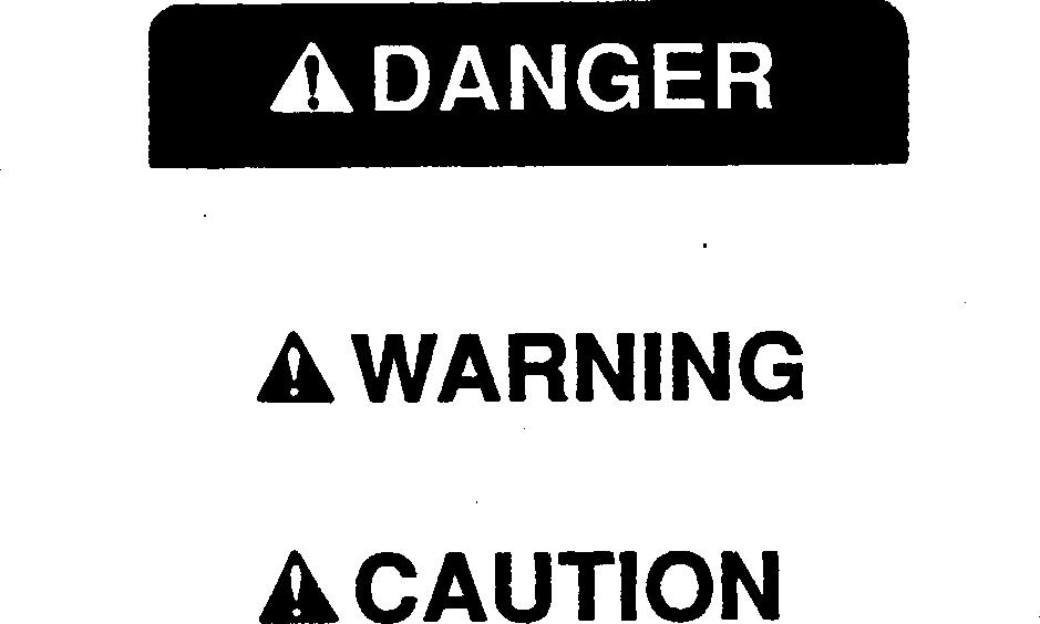
Understand Signal Words
A signal word DANGER, WARNING, or CAUTION is used with the safety-alert symbol. DANGER identifies the most serious hazards.
DANGER or WARNING safety signs are located near specific hazards. General precautions are listed on CAUTION safety signs. CAUTION also calls attention to safety messages in this manual.
Handle Fluids Safely Avoid Fires
When you work around fuel, do not smoke or work near heaters or other fire hazards.
Store flammable fluids away from fire hazards. Do not incinerate or puncture pressurized containers.
Make sure machine is clean of trash, grease, and debris.
Do not store oily rags; they can ignite and burn spontaneously.
10-05-1 TM2181 (29AUG06) 60 Series STS Combine Repair 083006 PN=7 T81389 –UN –07DEC88
10 05 1
DX,ALERT –19–29SEP98–1/1 Group 05 Safety
DX,SIGNAL –19–03MAR93–1/1
DX,FLAME –19–29SEP98–1/1 TS227 –UN –23AUG88 TS187 –19 –30SEP88
Prevent Battery Explosions
Keep sparks, lighted matches, and open flame away from the top of battery. Battery gas can explode.
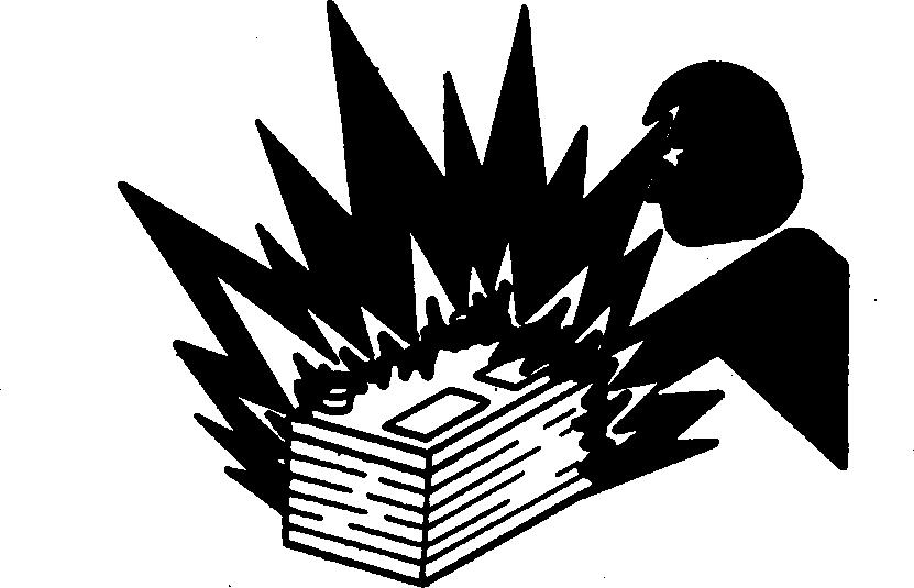
Never check battery charge by placing a metal object across the posts. Use a volt-meter or hydrometer.
Do not charge a frozen battery; it may explode. Warm battery to 16C (60F).
Safety 10-05-2 TM2181 (29AUG06) 60 Series STS Combine Repair 083006 PN=8 10 05 2
DX,SPARKS –19–03MAR93–1/1 TS204 –UN –23AUG88
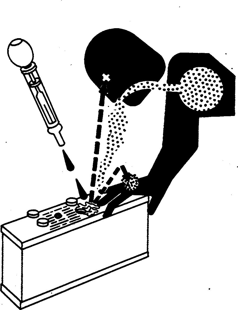
Handling Batteries Safely
CAUTION: Battery gas can explode. Keep sparks and flames away from batteries. Use a flashlight to check battery electrolyte level.
Never check battery charge by placing a metal object across the posts. Use a voltmeter or hydrometer.

Always remove grounded (-) battery clamp first and replace it last.
CAUTION: Sulfuric acid in battery electrolyte is poisonous. It is strong enough to burn skin, eat holes in clothing, and cause blindness if splashed into eyes.

Avoid the hazard by:
1. Filling batteries in a well-ventilated area.
2. Wearing eye protection and rubber gloves.
3. Avoiding breathing fumes when electrolyte is added.
4. Avoiding spilling or dripping electrolyte.
5. Use proper jump start procedure.
If you spill acid on yourself:
1. Flush your skin with water.
2. Apply baking soda or lime to help neutralize the acid.
3. Flush your eyes with water for 15 30 minutes. Get medical attention immediately.
If acid is swallowed:
1. Do not induce vomiting.
2. Drink large amounts of water or milk, but do not exceed 2 L (2 quarts).
3. Get medical attention immediately.
WARNING: Battery posts, terminals, and related accessories contain lead and lead compounds, chemicals known to the State of California to cause cancer and reproductive harm. Wash hands after handling.
Safety 10-05-3 TM2181 (29AUG06) 60 Series STS Combine Repair 083006 PN=9 TS203 –UN –23AUG88 TS204 –UN –23AUG88
10 05 3
AG,OUMX005,1408 –19–01MAY00–1/1
Prepare for Emergencies
Be prepared if a fire starts.
Keep a first aid kit and fire extinguisher handy. Keep emergency numbers for doctors, ambulance service, hospital, and fire department near your telephone.
Prevent Acid Burns
Sulfuric acid in battery electrolyte is poisonous. It is strong enough to burn skin, eat holes in clothing, and cause blindness if splashed into eyes.
Avoid the hazard by:
1. Filling batteries in a well-ventilated area.
2. Wearing eye protection and rubber gloves.
3. Avoiding breathing fumes when electrolyte is added.
4. Avoiding spilling or dripping electrolyte.
5. Use proper jump start procedure.
If you spill acid on yourself:
1. Flush your skin with water.
2. Apply baking soda or lime to help neutralize the acid.
3. Flush your eyes with water for 15 30 minutes. Get medical attention immediately.
If acid is swallowed:
1. Do not induce vomiting.
2. Drink large amounts of water or milk, but do not exceed 2 L (2 quarts).
3. Get medical attention immediately.
Safety 10-05-4 TM2181 (29AUG06) 60 Series STS Combine Repair 083006 PN=10 10 05 4
DX,FIRE2 –19–03MAR93–1/1
DX,POISON –19–21APR93–1/1 TS203 –UN –23AUG88 TS291 –UN –23AUG88
Handle Chemical Products Safely
Direct exposure to hazardous chemicals can cause serious injury. Potentially hazardous chemicals used with John Deere equipment include such items as lubricants, coolants, paints, and adhesives.
A Material Safety Data Sheet (MSDS) provides specific details on chemical products: physical and health hazards, safety procedures, and emergency response techniques.
Check the MSDS before you start any job using a hazardous chemical. That way you will know exactly what the risks are and how to do the job safely. Then follow procedures and recommended equipment.

(See your John Deere dealer for MSDS’s on chemical products used with John Deere equipment.)
Avoid High-Pressure Fluids
Escaping fluid under pressure can penetrate the skin causing serious injury.
Avoid the hazard by relieving pressure before disconnecting hydraulic or other lines. Tighten all connections before applying pressure.
Search for leaks with a piece of cardboard. Protect hands and body from high pressure fluids.
If an accident occurs, see a doctor immediately. Any fluid injected into the skin must be surgically removed within a few hours or gangrene may result. Doctors unfamiliar with this type of injury should reference a knowledgeable medical source. Such information is available from Deere & Company Medical Department in Moline, Illinois, U.S.A.
Safety 10-05-5 TM2181 (29AUG06) 60 Series STS Combine Repair 083006 PN=11 TS1132 –UN –26NOV90
10 05 5
DX,MSDS,NA –19–03MAR93–1/1
DX,FLUID –19–03MAR93–1/1 X9811 –UN –23AUG88
Service Accumulator Systems Safely
Escaping fluid or gas from systems with pressurized accumulators that are used in air conditioning, hydraulic, and air brake systems can cause serious injury. Extreme heat can cause the accumulator to burst, and pressurized lines can be accidentally cut. Do not weld or use a torch near a pressurized accumulator or pressurized line.
Relieve pressure from the pressurized system before removing accumulator.
Relieve pressure from the hydraulic system before removing accumulator. Never attempt to relieve hydraulic system or accumulator pressure by loosening a fitting.

Accumulators cannot be repaired.
Wait Before Opening High-Pressure Fuel System
High-pressure fluid remaining in fuel lines can cause serious injury. Only technicians familiar with this type of system should perform repairs. Before disconnecting fuel lines, sensors, or any other components between the high-pressure fuel pump and nozzles on engines with High Pressure Common Rail (HPCR) fuel system, wait a minimum of 15 minutes after engine is stopped.
Park Machine Safely
Before working on the machine:
• Lower all equipment to the ground.
• Stop the engine and remove the key.
• Disconnect the battery ground strap.
• Hang a "DO NOT OPERATE" tag in operator station.
Safety 083006 PN=12 10 05 6
DX,WW,ACCLA2 –19–22AUG03–1/1 TM2181 (29AUG06) 10-05-6 60 Series STS Combine Repair
DX,WW,HPCR2 –19–07JAN03–1/1
DX,PARK –19–04JUN90–1/1 TS230 –UN –24MAY89 TS1343 –UN –18MAR92 TS281 –UN –23AUG88
Support Machine Properly
Always lower the attachment or implement to the ground before you work on the machine. If the work requires that the machine or attachment be lifted, provide secure support for them. If left in a raised position, hydraulically supported devices can settle or leak down.
Do not support the machine on cinder blocks, hollow tiles, or props that may crumble under continuous load. Do not work under a machine that is supported solely by a jack. Follow recommended procedures in this manual.
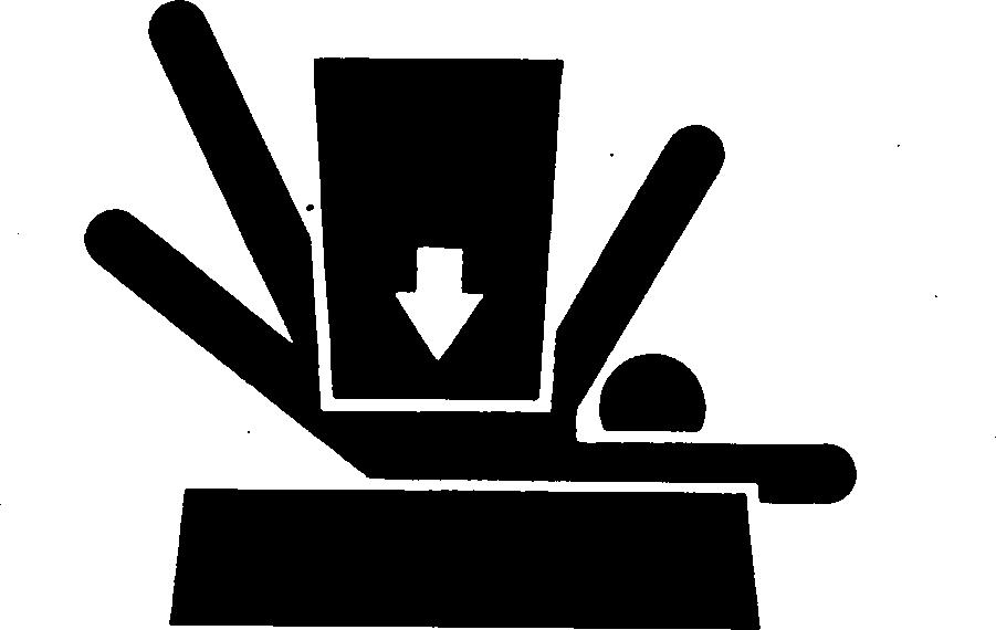
When implements or attachments are used with a machine, always follow safety precautions listed in the implement or attachment operator’s manual.
Wear Protective Clothing
Wear close fitting clothing and safety equipment appropriate to the job.
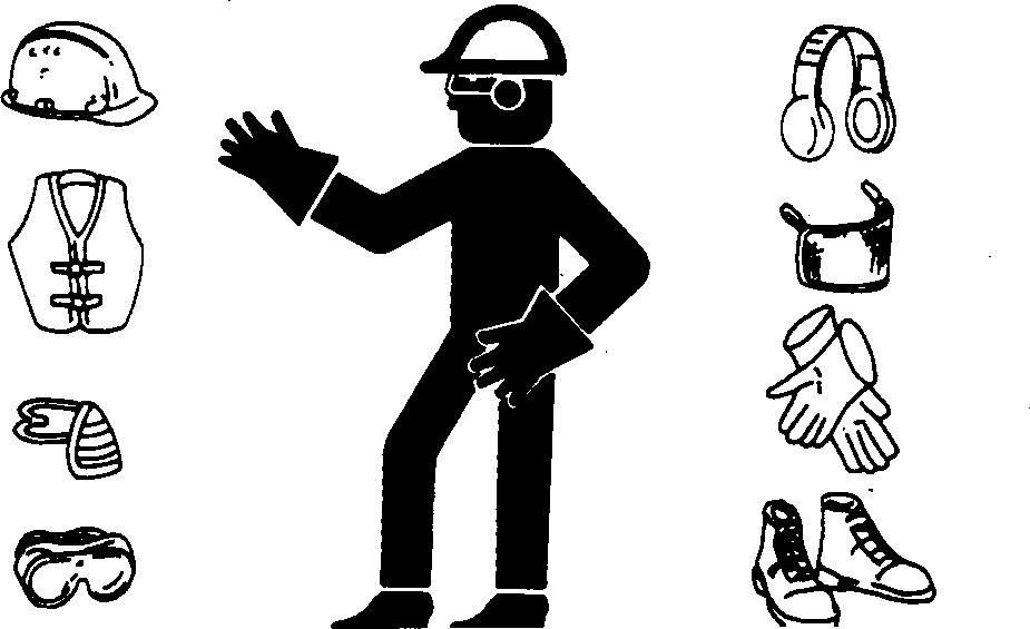
Prolonged exposure to loud noise can cause impairment or loss of hearing.

Wear a suitable hearing protective device such as earmuffs or earplugs to protect against objectionable or uncomfortable loud noises.
Operating equipment safely requires the full attention of the operator. Do not wear radio or music headphones while operating machine.
Work in Clean Area
Before starting a job:
• Clean work area and machine.
• Make sure you have all necessary tools to do your job.
• Have the right parts on hand.
• Read all instructions thoroughly; do not attempt shortcuts.
Safety 083006 PN=13 TS229 –UN –23AUG88
10 05 7
DX,LOWER –19–24FEB00–1/1 TM2181 (29AUG06) 10-05-7 60 Series STS Combine Repair
DX,WEAR –19–10SEP90–1/1
DX,CLEAN –19–04JUN90–1/1 T6642EJ –UN –18OCT88 TS206 –UN –23AUG88
Service Machines Safely
Tie long hair behind your head. Do not wear a necktie, scarf, loose clothing, or necklace when you work near machine tools or moving parts. If these items were to get caught, severe injury could result.

Remove rings and other jewelry to prevent electrical shorts and entanglement in moving parts.
Work In Ventilated Area
Engine exhaust fumes can cause sickness or death. If it is necessary to run an engine in an enclosed area, remove the exhaust fumes from the area with an exhaust pipe extension.
If you do not have an exhaust pipe extension, open the doors and get outside air into the area
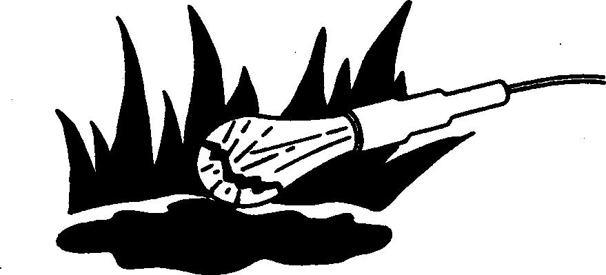
Illuminate Work Area Safely
Illuminate your work area adequately but safely. Use a portable safety light for working inside or under the machine. Make sure the bulb is enclosed by a wire cage. The hot filament of an accidentally broken bulb can ignite spilled fuel or oil.
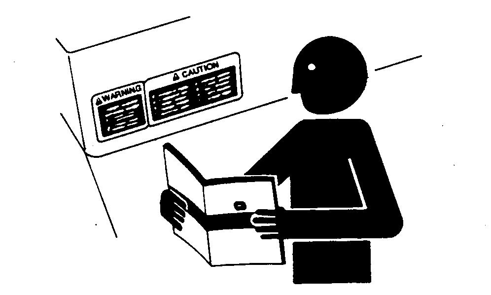
Replace Safety Signs
Replace missing or damaged safety signs. See the machine operator’s manual for correct safety sign placement.

Safety 10-05-8 TM2181 (29AUG06) 60 Series STS Combine Repair 083006 PN=14 10 05 8
DX,LOOSE –19–04JUN90–1/1
DX,AIR –19–17FEB99–1/1
DX,LIGHT –19–04JUN90–1/1
DX,SIGNS1 –19–04JUN90–1/1 TS201 –UN –23AUG88 TS223 –UN –23AUG88 TS220 –UN –23AUG88 TS228 –UN –23AUG88
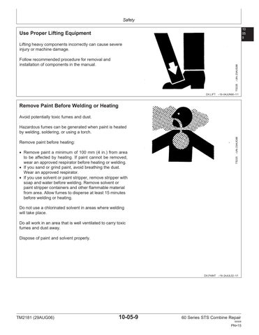
Use Proper Lifting Equipment
Lifting heavy components incorrectly can cause severe injury or machine damage.

Follow recommended procedure for removal and installation of components in the manual.
Remove Paint Before Welding or Heating
Avoid potentially toxic fumes and dust.
Hazardous fumes can be generated when paint is heated by welding, soldering, or using a torch.
Remove paint before heating:
• Remove paint a minimum of 100 mm (4 in.) from area to be affected by heating. If paint cannot be removed, wear an approved respirator before heating or welding.
• If you sand or grind paint, avoid breathing the dust. Wear an approved respirator.
• If you use solvent or paint stripper, remove stripper with soap and water before welding. Remove solvent or paint stripper containers and other flammable material from area. Allow fumes to disperse at least 15 minutes before welding or heating.
Do not use a chlorinated solvent in areas where welding will take place.
Do all work in an area that is well ventilated to carry toxic fumes and dust away.
Dispose of paint and solvent properly.
Safety 10-05-9 TM2181 (29AUG06) 60 Series STS Combine Repair 083006 PN=15 TS226 –UN –23AUG88
10 05 9
DX,LIFT –19–04JUN90–1/1
DX,PAINT –19–24JUL02–1/1 TS220 –UN –23AUG88
Avoid Heating Near Pressurized Fluid Lines
Flammable spray can be generated by heating near pressurized fluid lines, resulting in severe burns to yourself and bystanders. Do not heat by welding, soldering, or using a torch near pressurized fluid lines or other flammable materials. Pressurized lines can accidentally burst when heat goes beyond the immediate flame area.

Service Tires Safely
Explosive separation of a tire and rim parts can cause serious injury or death.
Do not attempt to mount a tire unless you have the proper equipment and experience to perform the job.

Always maintain the correct tire pressure. Do not inflate the tires above the recommended pressure. Never weld or heat a wheel and tire assembly. The heat can cause an increase in air pressure resulting in a tire explosion. Welding can structurally weaken or deform the wheel.
When inflating tires, use a clip-on chuck and extension hose long enough to allow you to stand to one side and NOT in front of or over the tire assembly. Use a safety cage if available.
Check wheels for low pressure, cuts, bubbles, damaged rims or missing lug bolts and nuts.
Safety 10-05-10 TM2181 (29AUG06) 60 Series STS Combine Repair 083006 PN=16 10 05 10
DX,TORCH –19–10DEC04–1/1
DX,RIM –19–24AUG90–1/1 TS211 –UN –23AUG88 TS953 –UN –15MAY90
Avoid Harmful Asbestos Dust
Avoid breathing dust that may be generated when handling components containing asbestos fibers. Inhaled asbestos fibers may cause lung cancer.
Components in products that may contain asbestos fibers are brake pads, brake band and lining assemblies, clutch plates, and some gaskets. The asbestos used in these components is usually found in a resin or sealed in some way. Normal handling is not hazardous as long as airborne dust containing asbestos is not generated.
Avoid creating dust. Never use compressed air for cleaning. Avoid brushing or grinding material containing asbestos. When servicing, wear an approved respirator. A special vacuum cleaner is recommended to clean asbestos. If not available, apply a mist of oil or water on the material containing asbestos.
Keep bystanders away from the area.
Safety 10-05-11 TM2181 (29AUG06) 60 Series STS Combine Repair 083006 PN=17 TS220 –UN –23AUG88
10 05 11
DX,DUST –19–15MAR91–1/1
Understand service procedure before doing work. Keep area clean and dry.
Never lubricate, service, or adjust machine while it is moving. Keep hands, feet , and clothing from power-driven parts. Disengage all power and operate controls to relieve pressure. Lower equipment to the ground. Stop the engine. Remove the key. Allow machine to cool.
Securely support any machine elements that must be raised for service work.
Keep all parts in good condition and properly installed. Fix damage immediately. Replace worn or broken parts. Remove any buildup of grease, oil, or debris.
On self-propelled equipment, disconnect battery ground cable (-) before making adjustments on electrical systems or welding on machine.
On towed implements, disconnect wiring harnesses from tractor before servicing electrical system components or welding on machine.
Construct Dealer-Made Tools Safely
Faulty or broken tools can result in serious injury. When constructing tools, use proper, quality materials, and good workmanship.

Do not weld tools unless you have the proper equipment and experience to perform the job.

Safety 10-05-12 TM2181 (29AUG06) 60 Series STS Combine Repair 083006 PN=18 10 05 12
Practice Safe Maintenance
DX,SERV –19–17FEB99–1/1
DX,SAFE,TOOLS –19–10OCT97–1/1 LX1016749 –UN –01JUL97 TS218 –UN –23AUG88
Use Proper Tools
Use tools appropriate to the work. Makeshift tools and procedures can create safety hazards.
Use power tools only to loosen threaded parts and fasteners.
For loosening and tightening hardware, use the correct size tools. DO NOT use U.S. measurement tools on metric fasteners. Avoid bodily injury caused by slipping wrenches.

Use only service parts meeting John Deere specifications.
Dispose of Waste Properly
Improperly disposing of waste can threaten the environment and ecology. Potentially harmful waste used with John Deere equipment include such items as oil, fuel, coolant, brake fluid, filters, and batteries.
Use leakproof containers when draining fluids. Do not use food or beverage containers that may mislead someone into drinking from them.
Do not pour waste onto the ground, down a drain, or into any water source.
Air conditioning refrigerants escaping into the air can damage the Earth’s atmosphere. Government regulations may require a certified air conditioning service center to recover and recycle used air conditioning refrigerants.
Inquire on the proper way to recycle or dispose of waste from your local environmental or recycling center, or from your John Deere dealer.

Safety 10-05-13 TM2181 (29AUG06) 60 Series STS Combine Repair 083006 PN=19 TS779 –UN –08NOV89
10 05 13
DX,REPAIR –19–17FEB99–1/1
DX,DRAIN –19–03MAR93–1/1 TS1133 –UN –26NOV90
Use Adequate Service Facilities
Keep the service area clean and dry. Wet or oily floors are slippery. Wet spots can be dangerous when working with electrical equipment.
Make sure the service area is adequately vented.
Periodically check the shop exhaust system for leakage. Engine exhaust gas is dangerous.
Be sure all electrical outlets and tools are properly grounded.
Use adequate light for the job at hand.
Service the machine on a level, hard-surfaced area.
Use lifting equipment and safety stands which have adequate strength for the job being performed.
Live With Safety
Before returning machine to customer, make sure machine is functioning properly, especially the safety systems. Install all guards and shields.

Safety 10-05-14 TM2181 (29AUG06) 60 Series STS Combine Repair 083006 PN=20 10 05 14
HX,1401,1005,A –19–11DEC92–1/1
DX,LIVE –19–25SEP92–1/1 TS231 –19 –07OCT88
Ground Speeds (Fast Idle) Two Speed Four
Wheel Drive
NOTE: Speeds shown are for combines equipped with 18.4 x 26 R1 rear tires. Except combines equipped with 35.5 x 32 R2 drive tires are shown with 28L x 26 R2 rear tires.
Group 10 Specifications
10-10-1
60
Combine Repair 083006 PN=21 10
TM2181 (29AUG06)
Series STS
10
1
Speed in Km/h (mph) Front Tire 2WD 2-Speed 4WD First Gear Second Gear Third Gear 30.5 x 32 R1 X 6.1 (3.8) 11.4 (7.1) 30.4 (19.0) 30.5 x 32 R1 Low High 4.7 (2.9) 5.4 (3.4) 7.3 (4.6) 9.1 (5.7) 12.1 (7.6) 18.1 (11.3) 800/65R32 X 6.1 (3.8) 11.4 (7.1) 30.4 (19.0) 800/65R32 Low High 4.7 (2.9) 5.4 (3.4) 7.3 (4.6) 9.1 (5.7) 12.1 (7.6) 18.1 (11.3) 30.5L x 32R2 X 6.3 (3.9) 11.7 (7.3) 31.2 (19.5) 30.5L x 32 R2 Low High 4.8 (3.) 5.5 (3.4) 7.4 (4.6) 9.3 (5.8) 12.3 (7.7) 18.5 (11.6) 30.5L x 32 R3 X 5.8 (3.6) 10.8 (6.8) 28.8 (18.0) 18.4 x 38 R1 X 5.9 (3.7) 11.1 (6.9) 29.5 (18.4) 18.4 x 38 R1 Low High 4.6 (2.9) 5.2 (3.3) 7.1 (4.4) 8.9 (5.6) 11.9 (7.4) 17.8 (11.1) 18.4 x 38 R2 X 6.1 (3.8) 11.4 (7.1) 30.4 (19.0) 18.4 x 38 R2 Low High 4.7 (2.9) 5.4 (3.4) 7.3 (4.6) 9.1 (5.7) 12.2 (7.6) 18.3 (11.4) 20.8 x 38 R1 X 6.1 (3.8) 11.4 (7.1) 30.4 (19.0) 20.8 x 38 R1 Low High 4.7 (2.9) 5.4 (3.4) 7.3 (4.6) 9.1 (5.7) 12.1 (7.6) 18.1 (11.3) 18.4 x 42 R1 X 6.3 (3.9) 11.8 (7.4) 31.3 (19.6) 18.4 x 42 R1 Low High 4.8 (3.0) 5.5 (3.4) 7.4 (4.6) 9.3 (5.8) 12.2 (7.6) 18.4 (11.5) 35.5 x 32 R2 X 6.8 (4.3) 12.7 (7.9) 33.8 (21.1) 35.5 x 32 R2 Low High 5.2 (3.3) 6 (3.8) 8.1 (5.1) 10.1 (6.3) 13.5 (8.4) 20.2 (12.6) 68 x 50-32, HF3 X 5.8 (3.6) 10.8 (6.8) 28.8 (18.0) 68 x 50-32, HF3 Low High 4.5 (2.8) 5.1 (3.2) 7 (4.4) 8.7 (5.4) 11.8 (7.4) 17.5 (10.9)
AG,OUO6022,1688 –19–24JUL00–1/1
Specifications 10-10-2 TM2181 (29AUG06) 60 Series STS Combine Repair 083006 PN=22 10 10
2 OUO6083,0000655 –19–22DEC03–1/1 Combine Model Front Tires Rear Tires Non-Powered Rear Axle Two Speed Powered Rear Axle 9560 STS 30.5L-32 18.4-26 7.4 m (24 ft 2 in.) 7.4 m (24 ft 2 in.) 9660 STS, 97560 STS and 9860 STS 30.5L-32 18.4-26 7.73 m (25 ft 3 in.) 8.19 m (26 ft 10 in.)
Turning Radius
Operating Speeds 9560 STS
Speeds shown are average and can vary from machine to machine. Speeds are rated at high idle with separator engaged, no load.
Operating speeds specifications and design subject to change without notice.
Slow Idle (Separator Off) (6.8 L Engine) 1300 rpm
Slow Idle (Separator Off) (8.1 L Engine) 1200 rpm
Mid Speed (Separator Off) (6.8 L Engine) 1850 rpm
Mid Speed (Separator Off) (8.1 L Engine) 1680 rpm
Fast Idle (Separator Off) (6.8 L Engine) 2550 rpm
Fast Idle (Separator Off) (8.1 L Engine) 2340 rpm
Full Load Rated Speed (6.8 L Engine) 2400 rpm Full Load Rated Speed (8.1 L Engine) 2200 rpm
TM2181 (29AUG06)
10-10-3
60 Series STS Combine Repair 083006 PN=23
Specifications
10 10 3
Speed
Engine
Separator Drive Shaft Speed 1546 rpm Main Countershaft Speed 1546 rpm Single Tine Separator Speed High Range 480 - 1300 rpm Low Range 230 - 600 rpm Feeder House Lower Shaft Speed Standard Variable Speed 520 - 780 rpm Heavy Duty Variable Speed 520 - 780 rpm Fixed Speed 520 rpm Fixed Speed Feeder House Drive Chain Speed 22 Tooth Fixed Speed Chain 48 rpm 26 Tooth Fixed Speed Chain 57 rpm 38 Tooth Fixed Speed Chain (Optional) 83 rpm Feed Accelerator Speed Feed Accelerator 440/800 rpm Feed Accelerator (Optional Slow Speed) 320/790 rpm Discharge Beater Speed 849 rpm Jackshaft Speed Right-Hand Jackshaft, Front 532 rpm Right-Hand Jackshaft, Rear 532 rpm Cleaning Fan Speed Standard Speed 500 - 1200 rpm Special Slow Speed 300 - 600 rpm Continued on next page OUO6083,0000DA0 –19–18JUL06–1/2
Specifications 10-10-4
60
Repair 083006 PN=24 10 10 4 OUO6083,0000DA0 –19–18JUL06–2/2 Elevator Speed Clean Grain Elevator 400 rpm Clean Grain Loading Auger 424 rpm Tailings Elevator, Lower Auger 405 rpm Tailings Elevator, Upper Auger 640 rpm Shoe Drive 297 rpm Conveyor Augers 433 rpm Unloading System Speed Unloading System Countershaft 1087 rpm Unloading Auger Gear Box, Input Shaft 450 rpm Unloading Vertical Auger 450 rpm Unloading Outer Auger 450 rpm Grain Tank Horizontal Augers 420 rpm Chopper Speed Chopper/Discharge Beater Jackshaft 2002 rpm Chopper (Two Speed) 1603/2500 rpm
TM2181 (29AUG06)
Series STS Combine
NOTE: Specifications and design subject to change without notice.
Specifications 10-10-5 TM2181 (29AUG06) 60 Series STS Combine Repair 083006 PN=25 10 Specifications—9560 STS Combine 10 5
Engine Make John Deere Model (6.8 L Engine) 6068HH Model (8.1 L Engine) 6081HH Type six-cylinder, in line, valve-in-head, air-to-air
diesel turbocharged Rated Power at 2400 rpm (6.8 L Engine) 198 kW (265 hp) Rated Power at 2200 rpm (8.1 L Engine) 198 kW (265 hp) Power Bulge at 2300 rpm (6.8 L Engine) 212 kW (284 hp) Power Bulge at 2100 rpm (8.1 L Engine) 212 kW (284 hp) Power Boost 220 kW (295 hp) Displacement (6.8 L Engine) 6.8 L (415 cu. in.) Displacement (8.1 L Engine) 8.1L (496 cu. in.) Firing Order 1-5-3-6-2-4 Air Cleaner Dry-type with safety element Thermostats (two) 82 C (180 F) Electrical System Type 12 volt, negative ground with 200 amp alternator Transmission Speeds Three Speeds Brakes Type Hydraulic Shoe Feed Accelerator Number of Wings 10 Separator Elements Threshing Elements Corn/Small Grain 15 Tines 18 Concave Number of Concaves 3 Number of Bars Per Concave Grain Front 20, Mid/rear 20; Corn 25 Separating Number of Grates 3 Continued on next page OUO6083,0000DA1 –19–18JUL06–1/2
aftercooled
60 Series STS Combine Repair 083006 PN=26 10 10 6 Discharge Beater Number of Wings 5 Grain Tank Capacity 7750 L (220 bu.) Capacity (Optional) 8850 L (250 bu.) Average Unloading rate 4650 L/min (132 bu/min) Maximum Unloading rate 5285 L/min (150 bu/min) Weight Corn Combine less header 13,053 kg (28,777 lbs) Turning Radius Rear Wheel Tread Width 3.3 m (10 ft. 10 in.) Turning radius 7.4 m (24 ft. 3 in.) Capacities Fuel Tank 757 L (200 gal) Cooling System w/heater (6.8 L Engine) 44 L (47 U.S. qts) Cooling System w/heater (8.1 L Engine) 53.3 L (56 U.S. qts) Engine Crankcase w/filter (6.8 L Engine) 32 L (34 U.S. qts) Engine Crankcase w/filter (8.1 L Engine) 29.5 L (31 U.S. qts) Transmission 9.6 L (10 U.S. qts) Final Drives 8 L (8.5 U.S. qts) Heavy Duty Feeder House Reverser Gear Case w/o cooler 2.3 L (4.75 U.S. pts) Heavy Duty Feeder House Reverser Gear Case w/ cooler 3.5 L (7.4 U.S. pts) Countershaft Drive Gear Case 1.2 L (2.5 U.S. pts) Loading Auger Gear Case 3.8 L (4 U.S. qts) Two Speed Separator Drive Gear Case 2.4 L (2.5 U.S. qts) Engine Gear Case w/transfer 21.3 L (22.5 U.S. qts) Hydraulic/Hydrostatic Reservoir 35 L (37 U.S. qts) OUO6083,0000DA1 –19–18JUL06–2/2 Discharge Grate Number of Grates 3
Specifications 10-10-6 TM2181 (29AUG06)
Dimensions—9560 STS Combine
NOTE: Dimension specifications subject to change without notice.
• For 18.4R38*** R1 Duals and 480/80R38 (149A8) R1, subtract 141 mm (5.6 in.)
• For 20.8R38** R1 Duals and 520/85R38 (155A8) R1, subtract 103 mm (4.1 in.)
• For 30.5L-32 14PR R1, subtract 111 mm (4.4 in.)
Refer to Ground Drive and Rear Axle Section b
Refer to Ground Drive and Rear Axle Section c
• For 30.5L-32 14PR R2, subtract 82 mm (3.2 in.)
• For 30.5LR32*** R1, subtract 118 mm (4.7 in.)
• For 800/65R32 (172A8) R1W, subtract 93 mm (3.7 in.)
aDimension is measured 1.22 m from grain spill point. This represents the unloading auger when centered over the grain cart.
bSee Front Tire Selection, Header Compatibility, Final Drives, Row Spacing Charts in Ground Drive and Rear Axle Section for specific dimensions.
cSee Rear Tire Selection, Tire Spacing, and Front to Rear Tire Compatibility Charts in Ground Drive and Rear Axle Section for specific dimensions.
Specifications 10-10-7
60 Series STS Combine Repair 083006 PN=27 10
TM2181 (29AUG06)
10 7
Dimensions 9560 STS 800/70R38 R1 Front Tires and 600/65R28 R1 Rear Tires A 8.36 m (27 ft. 4 in.) w/ 4.80 m (15 ft. 7 in.) Unload Auger 9.31 m (30 ft. 5 in.) w/ 5.64 m (18 ft. 5 in.) Unload Auger 10.22 m (33 ft. 5 in.) w/ 6.55 m (21 ft. 5 in.) Unload Auger B 8.36 m (27 ft. 4 in.) C 4.46 m (14 ft. 6 in.) D 4.02 m (13 ft. 2 in.) w/ 7750 L (220 bu.) Extensions 4.16 m (13 ft. 6 in.) w/ 8850 L (250 bu.) Extensions E 3.88 m (12 ft. 7 in.) F 0.57 m (1 ft. 9 in.) G 3.53 m (11 ft. 6 in.) H 5.30 m (17 ft. 4 in.) w/ 4.80 m (15 ft. 7 in.) Unload Auger 6.19 m (20 ft. 3 in.) w/ 5.64 m (18 ft. 5 in.) Unload Auger 7.05 m (23 ft. 1 in.) w/ 6.55 m (21 ft. 5 in.) Unloading Auger I 4.56 m (15 ft. 0 in.) w/ 4.80 m (15 ft. 7 in.) Unload Auger 4.78 m (15 ft. 7 in.) w/ 5.64 m (18 ft. 5 in.) Unload Auger 4.99 m (16 ft. 4 in.) w/ 6.55 m (21 ft. 5 in.) Unload Auger J 3.97 m (13 ft. 0 in.) w/ 4.80 m (15 ft. 7 in.) Unload Auger 4.19 m (13 ft. 7 in.) w/ 5.64 m (18 ft. 5 in.) Unload Auger 4.41 m (14 ft. 5 in.) w/ 6.55 m (21 ft. 5 in.) Unload Auger Ka 3.98 m (13 ft. 1 in.) w/ 4.80 m (15 ft. 7 in.) Unload Auger 4.21 m (13 ft. 8 in.) w/ 5.64 m (18 ft. 5 in.) Unload Auger 4.43 m
ft.
m
Unload Auger L
(14
15 in.) w/ 6.55
(21 ft. 5 in.)
M
OUO6083,0000DA2 –19–18JUL06–1/1
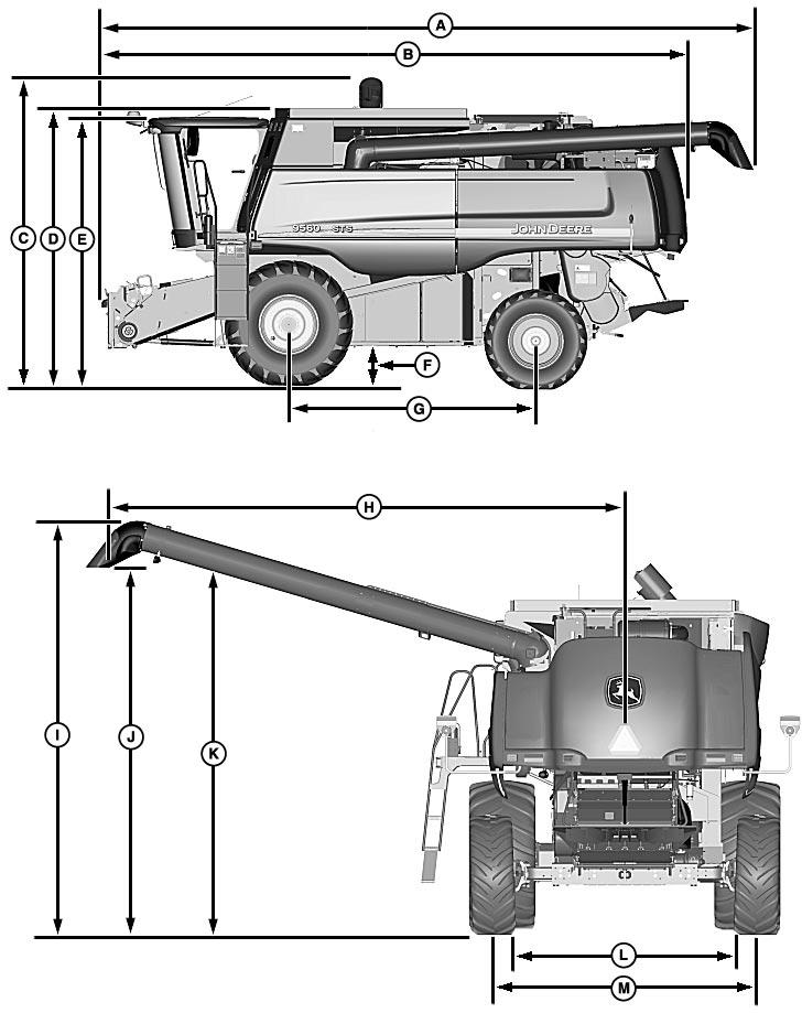
Specifications 10 10 Dimension Reference Points—9560 STS Combine 8 OUO6083,0000D9F –19–18JUL06–1/1 TM2181 (29AUG06) 10-10-8 60 Series STS Combine Repair 083006 PN=28 H85640 –UN –05APR06