CX31B CX36B
Compact Hydraulic Excavator
CX31B - PIN PW14-46519 - and higher
CX36B - PIN PX15-21105 - and higher

CX31B - PIN PW14-46519 - and higher
CX36B - PIN PX15-21105 - and higher
Part number S5PW0032E02
English
August 2010


Do not operate or perform any maintenance on this machine until all instructions found in the OPERATOR’S MANUAL and this MANUAL have been thoroughly read and understood. Improper operation or maintenance of this machine may cause accidents and could result in serious injury or death. Always keep the manual in storage. If it is missing or damaged, place an order with an authorized our Distributor for a replacement. If you have any questions, please consult an authorized our Distributor.
(1) Most accidents, which occur during operation, are due to neglect of precautionary measures and safety rules. Sufficient care should be taken to avoid these accidents. Erroneous operation, lubrication or maintenance services are very dangerous and may cause injury or death of personnel. Therefore all precautionary measures, NOTES, DANGERS, WARNINGS and CAUTIONS contained in the manual and on the machine should be read and understood by all personnel before starting any work with or on the machine.
(2) Operation, inspection, and maintenance should be carefully carried out, and safety must be given the first priority. Messages of safety are indicated with marks. The safety information contained in the manual is intended only to supplement safety codes, insurance requirements, local laws, rules and regulations.
(3) Messages of safety appear in the manual and on the machine : All messages of safety are identified by either word of "DANGER", "WARNING" and "CAUTION".
1) DANGER- Indicates an imminently hazardous situation which, if not avoided, will result in death or serious injury and is represented as follows:
3) CAUTION- Indicates a potentially hazardous situation which, if not avoided, may result in minor or moderate injury. It may also be used to alert against possible damage to the machine and its components and is represented as follows:
(4) It is very difficult to forecast every danger that may occur during operation. However, safety can be ensured by fully understanding proper operating procedures for this machine according to methods recommended by Manufacturer.
(5) While operating the machine, be sure to perform work with great care, so as not to damage the machine, or allow accidents to occur.
(6) Continue studying the manual until all Safety, Operation and Maintenance procedures are completely understood by all persons working with the machine.
2) WARNING- Indicates a potentially hazardous situation which, if not avoided, could result in death or serious injury and is represented as follows:
The proper and safe lubrication and maintenance for this machine, recommended by Manufacturer, are outlined in the OPERATOR’S MANUAL for the machine.
Improper performance of lubrication or maintenance procedures are dangerous and could result in injury or death. Read and understand the MANUAL before performing any lubrication or maintenance.
The serviceman or mechanic may be unfamiliar with many of the systems on this machine. This makes it important to use caution when performing service work. A knowledge of the system and or components is important before the removal or disassembly of any component.
Because of the size of some of the machine components, the serviceman or mechanic should check the weights noted in this manual. Use proper lifting procedures when removing any components. Weight of components table is shown in the section ; SPECIFICATIONS.
The following is a list of basic precautions that must always be observed.
(1) Read and understand all Warning plates and decal on the machine before Operating, Maintaining or Repairing this machine.
(2) Always wear protective glasses and protective shoes when working around machines. In particular, wear protective glasses when using hammers, punches or drifts on any part of the machine or attachments. Use welders gloves, hood/goggles, apron and the protective clothing appropriate to the welding job being performed. Do not wear loose fitting or torn clothing. Remove all rings from fingers, loose jewelry, confine long hair and loose clothing before working on this machinery.
(3) Disconnect the battery and hang a "Do Not Operate" tag in the Operators Compartment. Remove ignition keys.
(4) If possible, make all repairs with the machine parked on a firm level surface. Block the machine so it does not roll while working on or under the machine. Hang a "Do Not Operate" tag in the Operators Compartment.
(5) Do not work on any machine that is supported only by lift, jacks or a hoist. Always use blocks or jack
stands, capable of supporting the machine, before performing any disassembly.
Do not operate this machine unless you have read and understand the instructions in the OPERATOR’S MANUAL. Improper machine operation is dangerous and could result in injury or death.
(6) Relieve all pressure in air, oil or water systems before any lines, fittings or related items are disconnected or removed. Always make sure all raised components are blocked correctly and be alert for possible pressure when disconnecting any device from a system that utilizes pressure.
(7) Lower the bucket, dozer, or other attachments to the ground before performing any work on the machine. If this cannot be done, make sure the bucket, dozer, ripper or other attachment is blocked correctly to prevent it from dropping unexpectedly.
(8) Use steps and grab handles when mounting or dismounting a machine. Clean any mud or debris from steps, walkways or work platforms before using. Always face to the machine when using steps, ladders and walkways. When it is not possible to use the designed access system, provide ladders, scaffolds, or work platforms to perform safe repair operations.
(9) To avoid back injury, use a hoist when lifting components which weigh 20kg (45lbs) or more. Make sure all chains, hooks, slings, etc., are in good condition and are the correct capacity. Be sure hooks are positioned correctly. Lifting eyes are not to be side loaded during a lifting operation.
(10)To avoid burns, be alert for hot parts on machines which have just been stopped and hot fluids in lines, tubes and compartments.
(11)Be careful when removing cover plates. Gradually back off the last two capscrews or nuts located at opposite ends of the cover or device and carefully pry cover loose to relieve any spring or other pressure, before removing the last two capscrews or nuts completely.
(12)Be careful when removing filler caps, breathers and plugs on the machine. Hold a rag over the cap or plug to prevent being sprayed or splashed by liquids under pressure. The danger is even greater if the machine has just been stopped because fluids can be hot.
(13)Always use the proper tools that are in good condition and that are suited for the job at hand. Be sure you understand how to use them before performing any service work.
(14)Reinstall all fasteners with the same part number. Do not use a lesser quality fastener if replacements are necessary.
(15)Repairs which require welding should be performed only with the benefit of the appropriate reference information and by personnel adequately trained and knowledgeable in welding procedures. Determine type of metal being welded and select correct welding procedure and electrodes, rods or wire to provide a weld metal strength equivalent at least to that of the parent metal. Make sure to disconnect battery before any welding procedures are attempted.
(16)Do not damage wiring during removal operations. Reinstall the wiring so it is not damaged nor will be damaged in operation of the machine by contacting sharp corners, or by rubbing against some object or hot surface. Do not connect wiring to a line containing fluid.
(17)Be sure all protective devices including guards and shields are properly installed and functioning correctly before starting a repair. If a guard or shield must be removed to perform the repair work, use extra caution and replace the guard or shield after repair is completed.
(18)The maintenance and repair work while holding the bucket raised is dangerous due to the possibility of a falling attachment. Don’t fail to lower the attachment and place the bucket to the ground before starting the work.
(19)Loose or damaged fuel, lubricant and hydraulic lines, tubes and hoses can cause fires. Do not bend or strike high pressure lines or install ones which have been bent or damaged. Inspect lines, tubes and hoses carefully. Do not check for leaks with your hands. Very small (pinhole) leaks can result in a high velocity oil stream that will be invisible close to the hose. This oil can penetrate the skin and cause personal injury. Use card-board or paper to locate pinhole leaks.
(20)Tighten connections to the correct torque. Make sure that all heat shields, clamps and guards are installed correctly to avoid excessive heat, vibration or rubbing against other parts during operation. Shields that protect against oil spray onto hot exhaust components in event of a line, tube or seal failure must be installed correctly.
(21)Do not operate a machine if any rotating part is damaged or contacts any other part during operation. Any high speed rotating component that has been damaged or altered should be checked for balance before reusing.
(22)Be careful when servicing or separating the tracks (crawlers). Chips can fly when removing or installing a track (crawlers) pin. Wear safety glasses and long sleeve protective clothing. Tracks (crawlers) can unroll very quickly when separated. Keep away from front and rear of machine. The machine can move unexpectedly when both tracks (crawlers) are disengaged from the sprockets. Block the machine to prevent it from moving.
This manual contains information necessary for the maintenance and repair of hydraulic excavators. It is categorized into seven chapters: Specification, Maintenance, System, Disassembly, Troubleshooting, Engine and Installation Procedures for Optional Attachment.
• The Chapter "Specification" describes the specifications for the entire machine and replacement and repairing of attachments.
• The Chapter "Maintenance" contains material for service and adjustment of the entire machine.
• The Chapter "System" describes the operating system, including the hydraulic system, electric system, components, etc.
• The Chapter "Disassembly" describes the removal and installation of assemblies mounted on the upper structure and undercarriage, and the assembling and disassembling of the associated hydraulic equipment.
• The Chapter "Troubleshooting" describes how to find the faults in equipment.
• The Chapter "Engine" contains the complete "Maintenance Manual" provided by the engine supplier.
• The Chapter "Installation Procedures for Optional Attachment" describes the supplements added on request as required.
This Manual may be revised due to the improvement of products, modification of specifications, etc. There may be cases where the system on the actual machine may differ with the manual - this may be due to variation of specifications by countries. Contact your local distributor if you need clarification.
When ordering replacement or service parts, refer to the most recent Parts Catalog for the machine to get the correct replacement/service part number.
February, 2010
: PW14-45964~
: PX15-20658~
: PU09-08001~
: PJ06-08890~
: PW14-45001~ SK35SR-5 : PX15-20001~
: PW14-45001~ CX36B : PX15-20001~
CX50B : PJ06-08890~
: PJ06-08890~
: PW14-45001~ E35B : PX15-20001~
SK27SR-5 : PV13-33292~
2010 SK30SR-5 : PW14-46519~ SK35SR-5 : PX15-21105~
CX31B : PW14-46519~ CX36B : PX15-21105~
(KCM S.E.ASIA&OCE)
(CASE-AUS)
(CASE-NA)
(NH-AUS)
(KCM North America)
(CASE-NA)
(1) Understanding operating procedure
Read OPERATOR'S MANUAL carefully to understand the operating procedure.
(2) Cleaning machines
Remove soil, mud, and dust from the machine before bringng it into the service shop to prevent loss of work efficiency, damage of parts, and difficulty in rust prevention and dust protection while reassembling.
(3) Inspecting machines
Identify the parts to be disassembled before starting work. Determine the disassembling procedure, considering the workshop situations etc., and order necessary parts in advance.
(4) Recording
Record the following items for communication and prevention of recurring malfunction.
1. Inspection date and place.
2. Model name, applicable machine number, and hour meter read.
3. Trouble condition, place and cause.
4. Visible oil leakage, water leakage and damage.
5. Clogging of filters, oil level, oil quality, oil contamination and loosening of connections.
6. Result of consideration if any problem exists based on the operation rate per month calculated from hour meter indication after the last inspection date.
(5) Arrangement and cleaning in service shop
1. Tools required for repair work.
2. Prepare space to place the disassembled parts.
3. Prepare oil containers for draining oil etc.
WARNIN<G
(1) Wear appropriate clothes with long sleeves, safety shoes, safety helmet and protective glasses.
(2) Suspend warning tag "DO NOT OPERATE" from the doorknob or the operating lever, and have a preliminary meeting before starting work.
(3) Stop the engine before starting inspection and maintenance to prevent the operator being caught in machine.
(4) Identify the location of a first-aid kit and a fire extinguisher, and also where to make contact in a state of emergency.
(5) Choose a hard, level and safe place, and place the attachment on the ground securely.
(6) Use a lifter such as a crane to remove heavy parts (20 kg [45 lbs] or more) from the machine.
(7) Use proper tools, and replace or repair defective tools.
(8) Support the machine and attachment with supports or blocks if the work is performed in the lifted condition.
1. Before disconnecting pipes, release the hydraulic pressure of the system, or open the return side cover and take out the filter.
2. Carefully drain oil of the removed pipes into a containers without spilling on the floor.
3. Apply plugs or caps on the pipe ends to avoid oil spillage and dust intrusion.
4. Clean off the external surface of the equipment before disassembling, and drain hydraulic and gear oil before placing it on the workbench.
1. Do not disassemble, reassemble or modify the hydraulic equipment without the permission of the manufacturer, who is not responsible for the performance and function of the product after modification.
2. When disassembling and reassembling for unavoidable reason, refer the work to qualified personnel who have the specific knowledge or completed the parts service training.
3. Provide matching marks to facilitate reassembling work.
4. Before starting the work, read the manual of disassembling procedure, if it is provided, and decide whether the work can be performed by yourself.
5. Use the special jig and tools without fail if they are specified.
6. If it is hard to remove a part according to the procedure, do not try it by force but investigate the cause.
7. Place the removed parts in order and attach tags to facilitate the reassembling.
8. Note the location and quantity of parts commonly applied to multiple locations.
1. Ensure that the disassembled parts are free from seizure, interference and uneven contact.
2. Measure and record wear condition of parts and clearance.
3. If the problem is found in a part, repair or replace it with a new one.
1. Turn ON the ventilation fan or open windows to maintain good ventilation prior to starting the cleaning of parts.
2. Perform rough and finish cleaning before assembling.
3. Remove washing oil by air and apply clean hydraulic or gear oil for assembling.
4. Always replace the removed O-rings, backup rings and oil seals with new ones by applying grease in advance.
5. Remove dirt and moisture from and perform degreasing on the surface where liquid gasket to be applied.
6. Remove rust preventive agent from the new parts before use.
7. Fit bearings, bushings and oil seals using special jigs.
8. Assemble the parts utilizing matching marks.
9. Ensure all the parts are completely assembled after the work.
1. Ensure hydraulic oil and lubricant are properly supplied.
2. Perform air bleeding when :

a. Hydraulic oil changed

b. Parts of suction side piping replaced
c. Hydraulic pump installed
d. Slewing motor installed
e. Travel motor installed
f. Hydraulic cylinder installed
3. Perform air bleeding of the hydraulic pump and slewing motor after loosening the upper drain plug, starting the engine and keep it in low idle condition.
Complete the air bleeding when seeping of hydraulic oil is recognized, and tightly plug.
4. Perform air bleeding of the travel motor and the hydraulic cylinders by running the engine for more than 5 minutes at low speed without load.
5. Perform air bleeding of pilot line by performing a series of digging, slewing and travel.
6. Check hydraulic oil level after placing the attachment to the oil check position, and replenish oil if necessary.
Operation of the hydraulic equipment without filling hydraulic oil or lubricant or without performing air bleeding will result in damage to the equipment.
Do not allow the hydraulic cylinder to bottom on the stroke end just after the maintenance.
(1) Do not disassemble electrical equipment.
(2) Handle electrical equipment carefully - be careful not to drop. Exposure to electrical current can cause electrical shock.
(3) Turn the key OFF prior to connecting and disconnecting work.
(4) Disconnect the connector by holding it and pressing the lock. Do not pull the wire to apply force to the caulking portion.
(5) Connect the connector and ensure it is completely locked.
(6) Turn the key OFF prior to touching the terminal of starter or generator.
(7) Remove the ground (earth) terminal of battery when handling tools around the battery or its relay.
(8) Do not splash water on the electrical equipment and connectors during machine washing.
(9) Check for moisture adhesion inside the waterproof connector after pulling it out, since it is hard to remove moisture from the connector.
If moisture adhesion is found, dry it completely before the connection.
Battery electrolyte is hazardous.
Battery electrolyte is dilute sulfuric acid. Exposure of skin or eyes to this liquid will cause burning or loss of eyesight.
If the exposure occurs, take the following emergency measures and seek the advice of a medical specialist.
-When skin exposed :
Wash with water and soap sufficiently.
-When eyes exposed :
Immediately wash away with city water continuously for more than 10 minutes.
-When a large amount of the liquid flows out : Neutralize with sodium bicarbonate or wash away with city water.
-When swallowed :
Drink a large amount of milk or water.
-When clothes exposed:
Immediately undress and wash.
(1) O-ring
• Ensure O-rings have elasticity and are not damaged before use.
• Use the appropriate O-rings. O-rings are made of various kinds of materials having different hardness to apply to a variety of parts, such as the part for moving or fixed portion, subjected to high pressure, and exposed to corrosive fluid, even if the size is same.
• Fit the O-rings without distortion and bend.
• Always handle floating seals as a pair.
(2) Flexible hose (F hose)
• Use the appropriate parts. Different parts are used depending on the working pressure even the size of fitting and the total length of the hose is same.
• Tighten the fitting at the specified torque. Ensure no kink, tension, interference nor oil leakage is recognized.
(1) Refer repair welding to qualified personnel according to the appropriate procedure.
(2) Disconnect the ground (earth) cable of the battery before starting the repair. Failure to do so will cause damage to the electrical equipment.
(3) Move away the articles in advance that may cause fire if exposed to sparks.
(4) Before starting the repair of the attachment, do not fail to cover the plated surface of the piston rod with flameproof sheet to prevent it from being exposed to sparks.

(1) Run the engine at the place that is sufficiently ventilated.
(2) Industrial waste disposal
Dispose of the following parts according to the relevant regulations : Waste oil and waste container Battery
(3) Precautions for handling hydraulic oil
Exposure of eyes to hydraulic oil will cause inflammation. Wear protective glasses before handling to avoid an accident. If an eye is exposed to the oil, take the following emergency measures :
-When an eye exposed :
Immediately wash away with city water sufficiently till stimulative feeling vanishes.
-When swallowed :
Do not let vomit, and receive medical treatment immediately.
-When skin exposed:
Wash with water and soap sufficiently.
(4) Others
Use replacement parts and lubricants authorized as the manufacturer's genuine parts.
Introduction
Although this manual includes International System of Unit and Foot-Pound System of Units, if you need SI unit, refer to the following international system of units. Given hereinafter is an excerpt of the units that are related to this manual.
1. Etymology of SI Unites
French: Le Systeme International d' Unites
English: International System of Units
2. Construction of SI Unit System 1)
power of 10, where n is an integer)
ARM CYLINDER
LIGHT
BOOM
BOOM CYLINDER
BUCKET CYLINDER
ARM LINK
BUCKET SWING CYLINDER

DOZER CYLINDER
BATTERY
FUEL TANK
DOZER
TRAVEL LEVER
CANOPY
OPERATING LEVER
DOZER OPERATING LEVER
HYDRAULIC TANK
CONTROL VALVE
MONITOR PANEL (GAUGE CLUSTER)
RADIATOR
AIR CLEANER
RESERVOIR TANK
MUFFLER
ENGINE
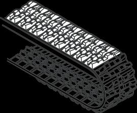
RUBBER CRAWLER SHOE
IDLER ASSY
LOWER ROLLER
UPPER ROLLER
SLEWING BEARING
TRAVEL MOTOR

OIL FILTER
SLEWING MOTOR
SWIVEL JOINT
HYDRAULIC PUMP


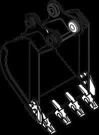
Bucket weight is shown with Japanese standard bucket weight.
Bucket weight is shown with Japanese standard bucket weight.
1. Keep trailer bed clean. Put chocks against truck wheels.
2. Use a ramp or loading deck. Ramps must be strong enough, have a low angle, and correct height. Load and unload machine on a level surface.
3. Travel machine onto ramps slowly. Center the machine over the trailer.
4. Lower all attachment.
5. Stop engine. Remove key from switch.
Do not put chains over or against hydraulic lines or hoses.
6. Fasten machine to trailer with chains or cables. During transportation, the bucket or attachments may hit the canopy or the cab. Therefore, set the machine in the transporting position by observing following points:
a. Extend the bucket cylinder fully.
b. Extend the arm cylinder fully.
c. Lower the boom.
d. If machine cannot be transported with arm cylinder fully extended, remove bucket or attachment and extend arm cylinder.
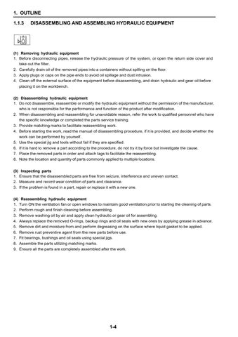
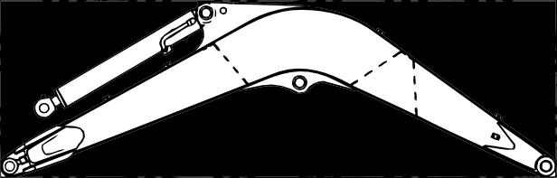
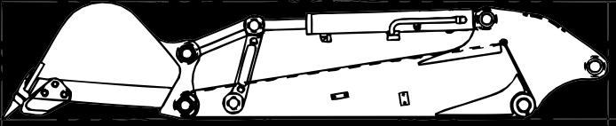
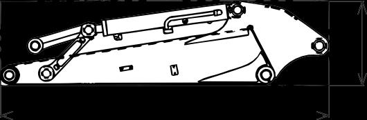
1. BOOM WITH ARM CYLINDER

5. DOZER w/o cylinder weight
CX31B,

foot pin dia.
outer dia.] Boom cylinder (rod side) pin dia. Pin dia. of arm end
Arm cylinder (head side) pin dia.
(rod side) mounting
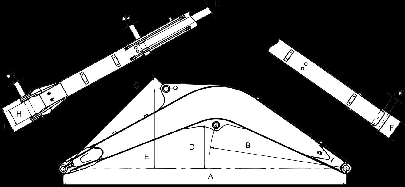
side)