ACOUSTIC TESTING OF BIO-BASED MASS TIMBER FLOOR ASSEMBLIES
For Sustainable Mass Timber Technologies


For Sustainable Mass Timber Technologies
© 2024
Research Team
Ethan Bloom - UO ESBL, FFA Architecture and Interiors
Mark Fretz (PI) - UO IHBE, ESBL
Andrew Loia - UO ESBL, FFA Architecture and Interiors
Dale Northcutt - UO IHBE, ESBL
Jason Stenson - UO IHBE, ESBL
Project Number 27172
Funding Acknowledgment
This work is generously supported by a 2019 Wood Innovations Program grant number 19-DG-11062765-736 from the USDA U.S. Forest Service.
Riverbank Acoustical Laboratories, ASTM Impact Sound Transmission (IIC) Full Testing Reports
Riverbank Acoustical Laboratories, ASTM Sound Transmission Loss (STC) Full Testing Reports

This work is copyrighted by the University of Oregon and provided under a CC BY-NC-ND 4.0 license. To view a copy of this license, visit http://creativecommons.org/licenses/by-nc-nd/4.0/ Please contact techtran@uoregon.edu if you would like additional permissions to use the materials.
According to UN estimates, the world’s population is increasingly dwelling in more densely populated urban areas, and by 2050 an estimated 2.5 billion additional people will live in cities.1 Therefore, architects, engineers and contractors are developing new construction technologies that simultaneously support low-carbon building design and human health.
One such construction technology with increasing market adoption in North America is panelized mass timber. The structural material offers advantages; it is renewable, biophilic,2 low-carbon, and it has the potential for off-site fabrication using digital workflows that can reduce construction schedules. Mass timber products are structurally well-suited for multifamily, multistory dwellings in floor-ceiling applications
given their aesthetic properties, speed of construction, reduced weight and floor-to-floor heights; however, the monolithic bare wood material is resonant, which requires further acoustic isolation as a floor-ceiling assembly to meet jurisdictional requirements in many applications.
While mass timber panels in isolation have acoustic limitations, many mass timber panels that are part of an assembly can achieve high airborne and impact sound transmission performance. However, the design and construction industry is working to improve the environmental performance of the floor-ceiling assemblies, which includes consideration of individual components such as a reduction or elimination of concrete, higher content of bio-based
materials, and designing assemblies for disassembly and reuse. For these alternate new assemblies to be adopted in construction projects, they must be tested to ASTM standards and meet or exceed code-required performance thresholds. With increasing population density, acoustic spatial isolation and freedom from urban noise intrusion will be important considerations for the satisfaction and long-term health of building occupants.3,4
This report defines several new mass timber floor-ceiling assemblies that are designed for disassembly and employ bio-based and lower carbon materials, while exposing the biophilic visual properties of mass timber. ASTM laboratory testing was performed to determine whether the assemblies meet or exceed housing code requirements.

TIMBER ACOUSTICS + CODE REQUIREMENTS
Using wood to create spatial acoustic separation presents special problems and requires additional consideration to acoustic separation for room-to-room floor and wall assemblies. Long prized as a material for musical instruments, wood is a resonant material with low density and transmits sound readily. Therefore, mass timber for wall and floor construction needs to be designed as part of an assembly that includes a mixture of dense materials and decoupled sound pathways.
Adoption of mass timber construction in the United States requires meeting performance-based codes and standards for fire, seismic and acoustics. Acoustic standards are established by multiple groups,
including American National Standards Institute (ANSI), American Society for Testing and Materials (ASTM), Facility Guidelines Institute (FGI), Housing and Urban Development (HUD), and International Code Council (ICC). Metrics used by these groups to evaluate acoustic performance include sound transmission class (STC), impact isolation class (IIC), and noise reduction coefficient (NRC) ratings.
STC, quantified in decibels (dB), measures how effective an assembly can reduce transmission of airborne sound from one space to another, i.e., block sound from getting through to the other side. IIC ratings, also measured in dB, are particular to floor-ceiling assemblies and gauge their effectiveness in reducing the transmission of impact sound, such as those generated from footsteps or fallen objects. Finally, NRC ratings are indicated by a number between 0 and 1, and are used to measure the ability
for an assembly to absorb sound. NRC is often used in applications to reduce reverberations or echo inside a space. This study investigates acoustic performance of mass timber assemblies in terms of STC and IIC, but excludes NRC evaluation.
In multi-family housing buildings in the United States, minimum acoustic separation requirements exist for demising walls and floors, which separate tenant spaces, and the International Building Code (IBC) specifies either a field-tested rating of 45 dB or a lab-tested rating of 50 dB for impact transfer and sound transfer through floor and wall assemblies, using ASTM accepted test methods.5 Other occupancy types generally benefit from similar STC and IIC values as minimum of “good performance” in support of indoor environmental quality.6 Spaces generating higher noise (e.g., mechanical rooms), or spaces requiring additional privacy, may require STC

ratings above 60 dB. Alone, a 5-ply CLT floor with a thickness of 6.875” has an STC rating of 41.7 Therefore, to be successfully integrated into buildings of all occupancy types, CLT assemblies must be augmented with sound attenuating materials or systems to improve their acoustic performance.
With projected population growth and increasing housing density in urban environments, noise control will be necessary for new building materials to ensure physical and mental health and well-being. For mass timber to simultaneously address environmental health, occupant wellness, and construction feasibility concerns, wall and floor assemblies need to be developed across multiple stakeholder groups and tested in field and laboratory settings for acoustic performance.
Primary strategies to increase the acoustic performance of an assembly include the addition of mass, sound barriers to close sound pathways, and decouplers.7 Increasing mass and the use of sound barriers allow for better deflection and/or absorption of noise, providing better sound control. Utilization of decouplers, products that reduce the direct surface-to-surface area between connected materials in an assembly, limit the pathways available for sound to travel through that assembly. Light-frame construction assemblies provide room to incorporate such strategies above, below, and/ or within the assembly, as structural elements are spaced apart and finishes with mass, such as gypsum board, are included for fire resistance. In mass timber assemblies, however, the solid structure limits acoustic materials to either side of the panel rather than
within. In the case of floor-ceiling assemblies, for aesthetic and biophilic reasons, it is common for designers working with mass timber products to expose the ceiling side of the timber structure, further limiting placement of most acoustic components to above the panel.7 These limitations set the parameters for developing unique solutions to address noise control in mass timber assemblies.
Timber alone does not adequately reduce sound transmission for most construction applications due to its inherent lack of mass. Therefore, concrete toppers are typically poured above floor-ceiling assemblies to add mass and improve acoustical performance. These concrete layers have environmental implications, as these cementitious products can counteract some of the embodied carbon benefits timber products provide. They also result in a composite
assembly whose layers are difficult, if not impossible to separate from one another, hindering the potential for material reuse or recycling at the end of a building’s lifespan. Alternative strategies such as bio-based materials and sleeper studs with decouplers, as tested in this study, can significantly carry acoustic performance above STC and IIC required thresholds while reducing some of the drawbacks in traditional methods of increasing mass.
As demand for new construction brings more people into urban areas, concerns surrounding environmental noise are to be expected. Sound becomes noise when it is unwanted, and there is evidence to support noise as an environmental stressor associated with adverse outcomes on psychological and physiological well-being.8,9 A multitude of studies on environmental noise and its correlations to different negative health outcomes have been explored. The most widespread and well understood response to noise is general annoyance which can affect quality of life.3 Studies on sleep have found noise to negatively affect sleep quality in terms of falling asleep and waking during the night. Poor sleep has immediate next-day repercussions on mood and performance; chronic exposure to nighttime noise can be linked to both cognitive and cardiovascular problems.10 Noise effects cognition, particularly in children, and has been shown to impair learning, reading comprehension and long-term memory.11 Noise has also negatively correlations to emotional/conduct disorders and hyperactivity.12 Studies linking noise to cardiovascular issues such as hypertension and heart disease have also been reported.13 Quality evidence for other reported adverse
correlations is limited by a low number of studies, and more robust studies are needed in these areas.
Embodied carbon of a material is defined by the total amount carbon emissions released during the lifecycle of that material, from extraction, manufacturing, transportation, construction, through disposal.14 These emissions occur over the product’s lifespan, and often have pronounced hotspots during the manufacturing stages.15
The building sector is responsible for about 42% of annual global CO2 emissions. Of that, 27% comes from operational emissions, or services required to power a building such as heating, cooling, and lighting. The remainder is attributed to resource extraction, material production, construction, and waste. The embodied carbon of cement, iron, steel and aluminum alone account for 15% of annual global CO2 emissions.15 As building operational efficiency increases, embodied carbon emissions are expected to make up a larger share of the sector’s carbon footprint. Increased demand for new building floor area in urban centers will further amplify the role of embodied carbon.
Mineral-based materials like concrete and steel generally require vast amounts of fossil fuel energy to process raw materials into desired products, making them materials with high embodied carbon. Fossil fuels require extremely long timelines to form, and their use as feedstock energy greatly exceeds their rate of renewal, creating one-way emissions of CO2 to the atmosphere that are essentially permanent on a human timescale and increasing radiative forcing, or the rate of energy entering the atmosphere
compared to the rate at which it leaves.16
Some emissions are caused by natural chemical processes. A notable example is the calcination of limestone to lime in clinker production, a process responsible for more than half of CO2 emissions in the production of Portland cement.17 Dependence on non-renewable resources and continued use of finite minerals will further reduce their availability, impact ecosystems, and contribute greenhouse gases emissions.
Photosynthesis allows vegetation to actively remove carbon dioxide from the atmosphere, sequestration carbon in their fibers, decreasing radiative forcing and producing a cooling effect. The accumulated carbon is stored as biomass, allowing plants to act as an atmospheric carbon sink. While the harvest of bio-based products stops their carbon intake at that point, the resulting products can store or sequester that biogenic carbon throughout their life. If and when these plants are replanted, carbon stocks can be stored in both urban and forest pools simultaneously. The longer the functional lifespan of these bio-based products, the longer carbon is securely stored away from the atmosphere.18
Another advantage of bio-based materials is their primary inputs are widely distributed resources, such as water, carbon dioxide, and energy from the sun, making them inherently low-embodied energy.19 When lowcarbon materials are substituted in place of high-embodied carbon ones, immediate emissions savings are achieved by reducing the one-way flow of fossil fuels.20 The renewability of biomass offers resource security, and regrowth creates a potential for material turnover compared to the single-use nature of non-renewable resources. Emissions from bio-based materials are part of a two-way process between

the atmosphere and biosphere (aka the carbon cycle) and can slow the contribution to long-term increased concentrations of atmospheric CO2 Biogenic emissions can be considered temporary if re-sequestration of those emissions, through re-planting, regrowth, and restoration, are assured in a rapid enough timeframe.21
Backed by sustainable forestry, mass timber construction in place of traditional concrete and steel can reduce the embodied carbon of a building’s superstructure and offer significant climate change mitigation opportunities. The additional materials needed for insulation and acoustical properties of roof, wall, and floor assemblies should focus on low-carbon materials to reduce their negative impact.
A transition to bio-based materials with low embodied carbon, particularly fast-growing materials like straw or hemp, can radically decrease the carbon footprint of a building. While timber can offer a lower carbon alternative to concrete and steel, it needs time for new forests to compensate for its initial embodied emissions through carbon uptake. Due to the longer rotation periods of forests, sequestration lags behind emissions caused by harvest, and the longer payback period carries a greater carbon debt and risk. Fastgrowing bio-based materials do not require long rotation periods. Their rapid carbon uptake offers greater assurance to carbon neutrality, a benchmark that can be achieved within a timeframe that may address the urgency of climate mitigation.22
1. United Nations. 2016. “The World’s Cities in 2016 - Data Booklet.” United Nations, Department of Economic and Social Affairs, Population Division. http://www.un.org/en/development/ desa/population/publications/pdf/ urbanization/the_worlds_cities_in_2016_ data_booklet.pdf.
2. Burnard, Michael D., and Andreja Kutnar. 2015. “Wood and Human Stress in the Built Indoor Environment: A Review.” Wood Science and Technology 49 (5): 969–86.
3. Guski, Rainer, Dirk Schreckenberg, and Rudolf Schuemer. 2017. “WHO Environmental Noise Guidelines for the European Region: A Systematic Review on Environmental Noise and Annoyance.” International Journal of Environmental Research and Public Health 14 (12): 1539.
4. Heroux*, Marie-Eve, and Jos Verbeek. 2016. “World Health Organization Environmental Noise Guidelines for the European Region: From Scientific Evidence to Formulation of Recommendations.” ISEE Conference Abstracts. https://doi.org/10.1289/ isee.2016.3686.
5. International Code Council. 2018. “International Building Code.” Falls Church, Va.: International Code Council.
6. U.S. Green Building Council, Inc. 2024. www.usgbc.org/credits/eq10.
7. McLain, R. (2018). Acoustics and mass timber: Room-to-room noise control. https://www.woodworks.org/wpcontent/uploads/wood_solution_paperMASS-TIMBER-ACOUSTICS.pdf
8. Stansfeld, S. A., & Matheson, M. P. (2003b). Noise pollution: Non-auditory effects on health. British Medical Bulletin, 68(1), 243–257. https://doi. org/10.1093/bmb/ldg033
9. Jarosińska, D., Héroux, M.-È., Wilkhu, P., Creswick, J., Verbeek, J., Wothge, J., & Paunović, E. (2018). Development of the WHO environmental noise guidelines for the European Region: An introduction. International Journal of Environmental Research and Public Health, 15(4), 813. https://doi.org/10.3390/ijerph15040813
10. Basner, Mathias, and Sarah McGuire. 2018. “WHO Environmental Noise
Guidelines for the European Region: A Systematic Review on Environmental Noise and Effects on Sleep.” International Journal of Environmental Research and Public Health 15 (3): 519.
11. Clark, Charlotte, and Katarina Paunovic. 2018a. “WHO Environmental Noise Guidelines for the European Region: A Systematic Review on Environmental Noise and Cognition.” International Journal of Environmental Research and Public Health 15 (2): 285.
12. Clark, C., & Paunovic, K. (2018). Who environmental noise guidelines for the European Region: A systematic review on environmental noise and quality of life, wellbeing and Mental Health. International Journal of Environmental Research and Public Health, 15(11), 2400. https://doi.org/10.3390/ ijerph15112400
13. Kempen, Elise van, Maribel Casas, Göran Pershagen, and Maria Foraster. 2018. “WHO Environmental Noise Guidelines for the European Region: A Systematic Review on Environmental Noise and Cardiovascular and Metabolic Effects: A Summary.” International Journal of Environmental Research and Public Health 15 (2): 379.
14. United States Environmental Protection Agency. 2024. www.epa. gov/greenerproducts/what-embodiedcarbon
15. Why the built environment?. Architecture 2030. (n.d.). https://www. architecture2030.org/why-the-builtenvironment/
16. MIT News. “Explained: Radiative Forcing.” Massachusetts Institute of Technology. 2010. https://news.mit. edu/2010/explained-radforce-0309
17. Petek Gursel, A., Masanet, E., Horvath, A., & Stadel, A. (2014). Lifecycle inventory analysis of Concrete Production: A Critical Review. Cement and Concrete Composites, 51, 38–48. https://doi.org/10.1016/j. cemconcomp.2014.03.005
18. Hawkins, W., Cooper, S., Allen, S., Roynon, J., & Ibell, T. (2021). Embodied Carbon Assessment using a dynamic climate model: Case-study comparison of a concrete, steel and timber building
structure. Structures, 33, 90–98. https:// doi.org/10.1016/j.istruc.2020.12.013
19. Hart, J., & Pomponi, F. (2020). More timber in construction: Unanswered Questions and future challenges. Sustainability, 12(8), 3473. https://doi.org/10.3390/su12083473
20. Lippke, B., Oneil, E., Harrison, R., Skog, K., Gustavsson, L., & Sathre, R. (2011). Life cycle impacts of forest management and wood utilization on carbon mitigation: Knowns and unknowns. Carbon Management, 2(3), 303–333. https://doi.org/10.4155/cmt.11.24
21. Breton, C., Blanchet, P., Amor, B., Beauregard, R., & Chang, W.-S. (2018). Assessing the climate change impacts of biogenic carbon in buildings: A critical review of two main dynamic approaches. Sustainability, 10(6), 2020. https://doi. org/10.3390/su10062020
22. Pittau, F., Krause, F., Lumia, G., & Habert, G. (2018). Fast-growing biobased materials as an opportunity for storing carbon in exterior walls. Building and Environment, 129, 117–129. https:// doi.org/10.1016/j.buildenv.2017.12.006
CLT FLOOR TESTS
This section defines the process of surveying and testing the acoustic performance of CLT floor assemblies for sound transmission (STC), impact isolation (IIC).
Laboratory testing was performed at Riverbank Acoustical Laboratories in Geneneva, Illinois. CLT samples were shipped to the lab wrapped and covered during transport.
CLT is a light-weight, high strength product. While these inherent properties provide structural advantages they can work against
the product in terms of acoustic performance, as sound can travel easily through the light, rigid material. Therefore, to be successfully integrated into buildings of all occupancy types, CLT assemblies must be augmented with sound attenuating materials or systems to improve their acoustic performance.
In common CLT assemblies, materials used to augment acoustic performance (e.g., concrete topping slabs atop an acoustical separation mat), typically result in an integrated, composite system. One drawback to this approach, however, is the limited ability to disassemble, recycle, or reuse these composite panels at the end of a building’s life. Additionally, these integrated materials are often high in embodied carbon1, and/or made of fossil fuel-based synthetic materials.
CLT ACOUSTIC ASSEMBLY SURVEY & DEVELOPMENT OF BIOBASED ALTERNATIVES
A review of over 600 published mass timber floor assemblies, as well as untested novel assemblies, was conducted to document known acoustic performance data and identify desirable CLT assemblies based on construction technique, performance, aesthetics, and cost. This review was used in consultation with industry stakeholders, including manufacturers, architects, engineers, acousticians, developers, and contractors, to develop nine (9) novel, previously untested assemblies in North America with publicly available ASTM test results for laboratory testing of acoustic performance.
The developed floor assemblies are
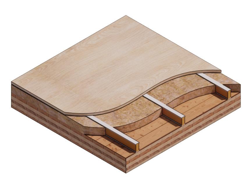
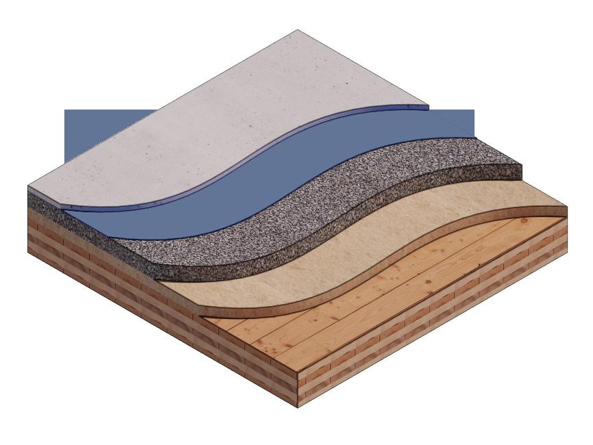
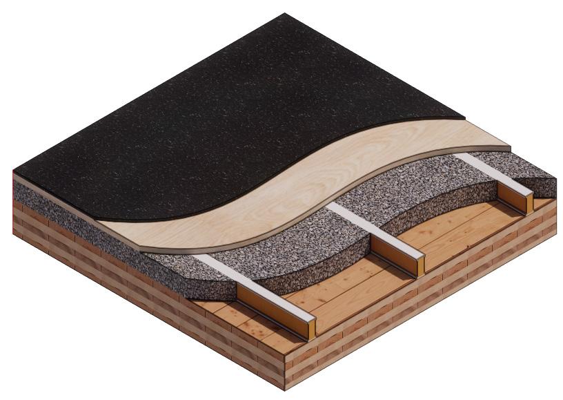
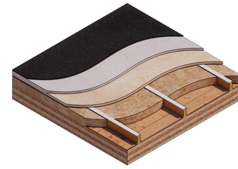
described in more detail in Section 02 of this report. All developed assemblies utilize 5-ply CLT panels as the wood substrate to provide a minimum baseline fire resistance regardless of sound attenuating materials added. For these remaining assembly layers, an emphasis was placed on bio-based, low-carbon, and easily disassembled materials in lieu of the more common mass timber floor assembly components that utilize synthetic or composite materials.
North American accredited laboratories were considered for ASTM testing and one selected based on availability, timeline and equipment capacity, with particular attention given to accommodating the unique size and weight of mass timber panels and the ability to procure additional materials required for constructing the built-
up assemblies. All floor assemblies were tested to ASTM E90-09 (2016) standards at Riverbank Acoustical Laboratories (Geneva, IL). The single number rating of the specimen was calculated according to ASTM E413-22. The transmission loss values are for a single direction of measurement.
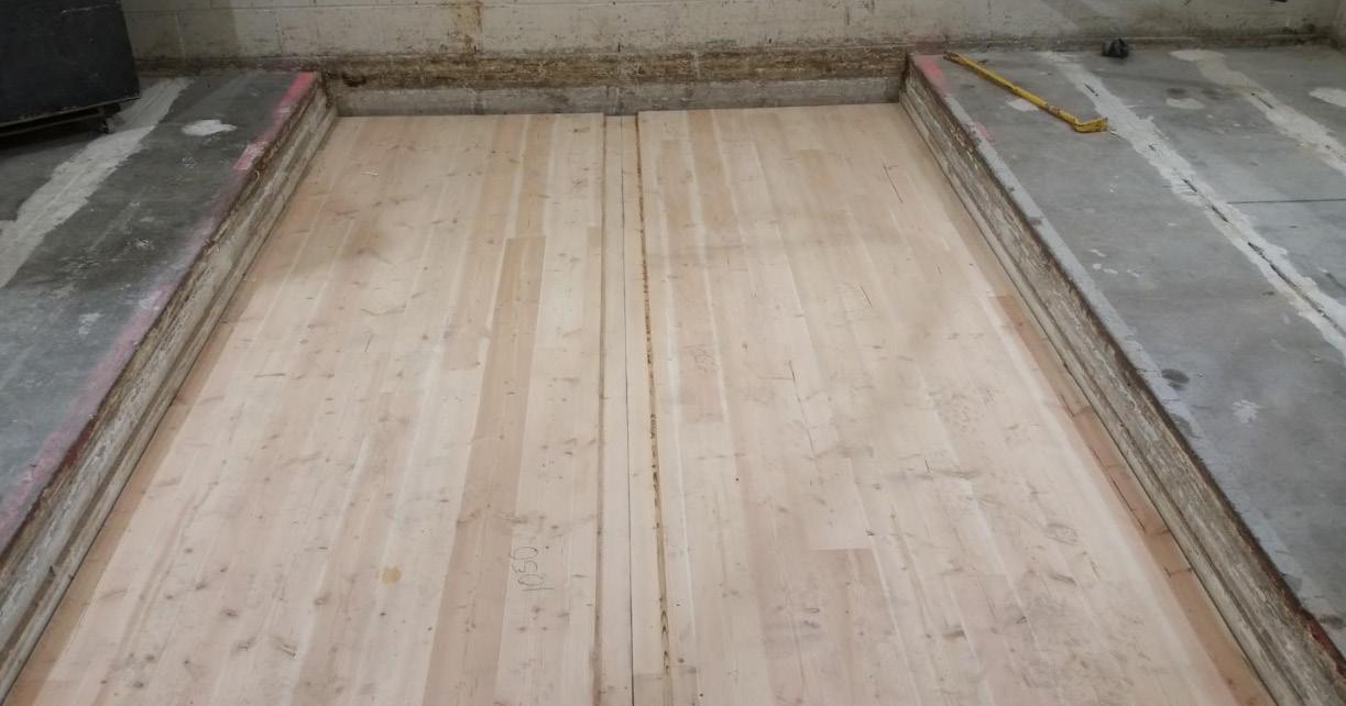
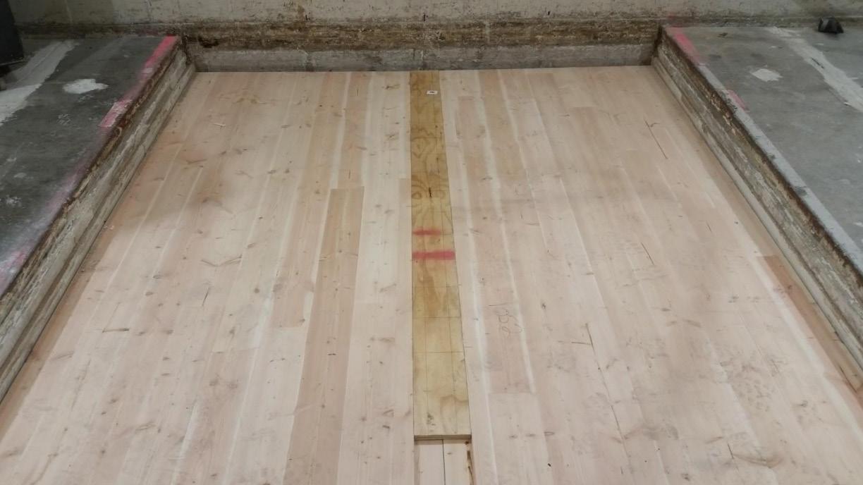
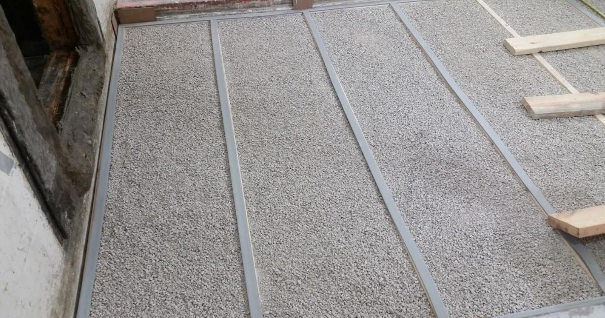
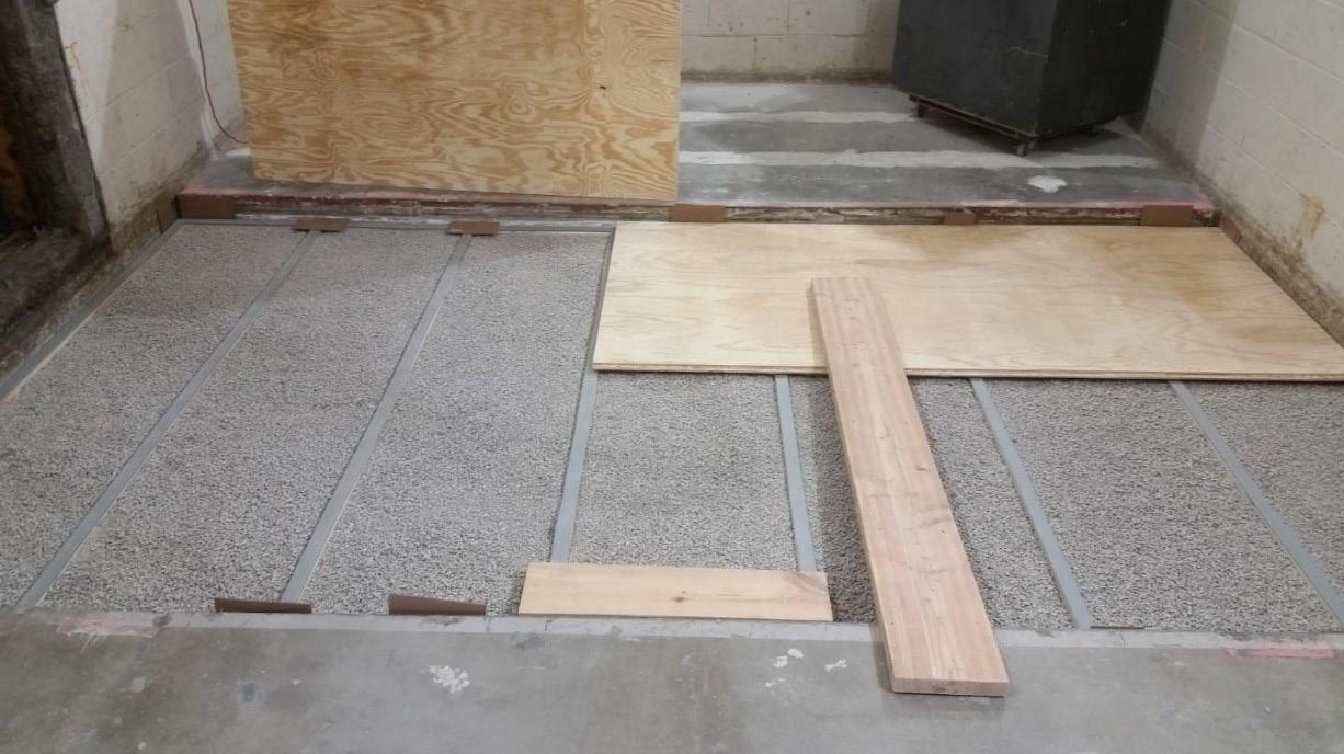
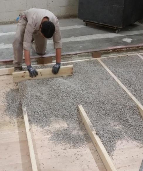
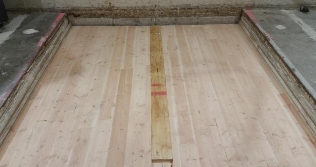
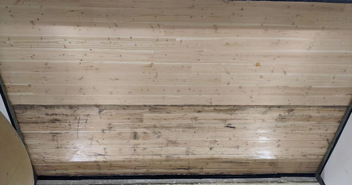
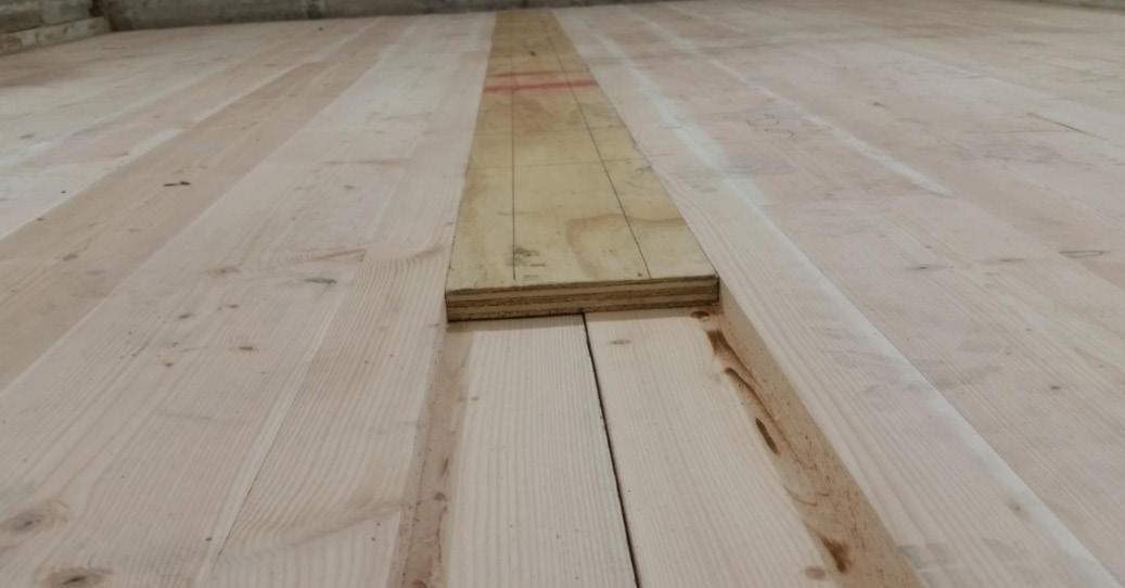
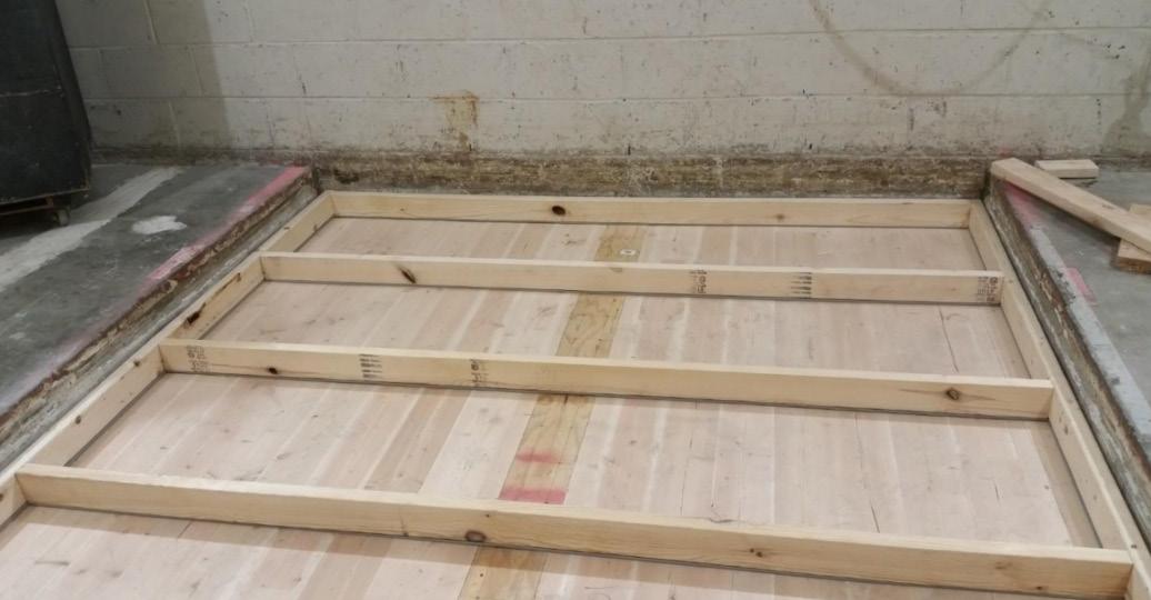
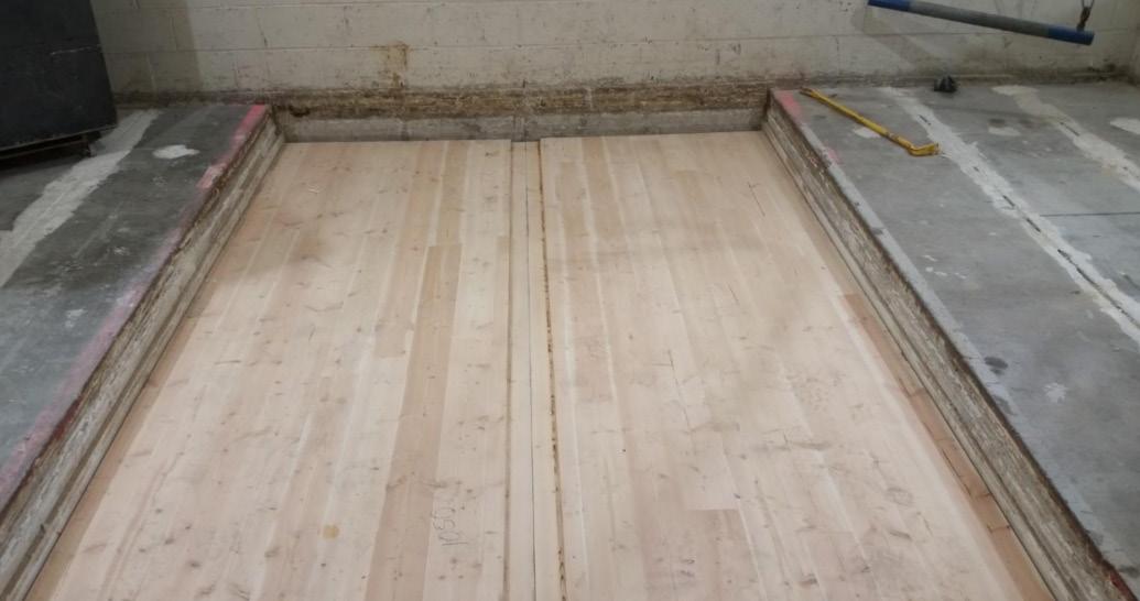
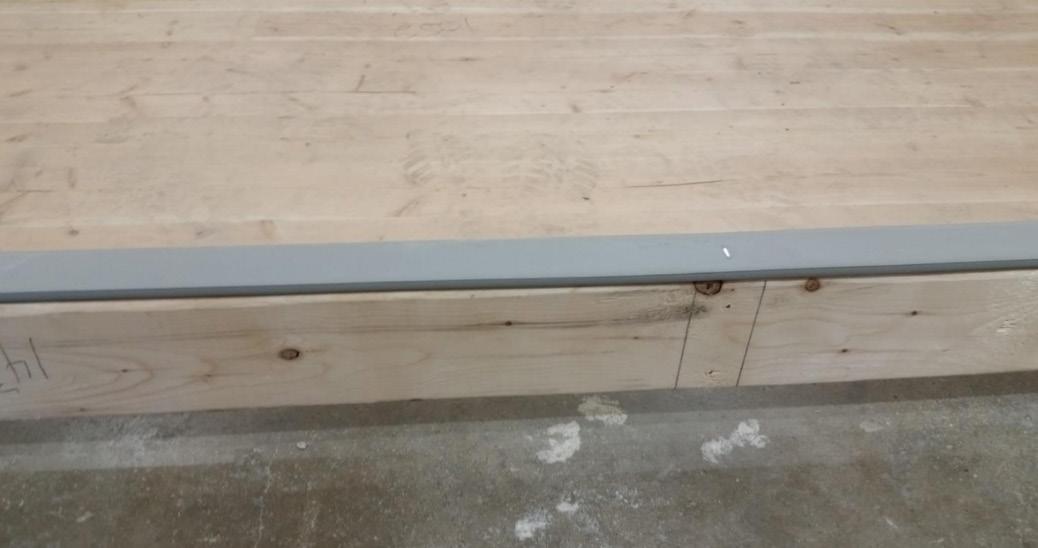
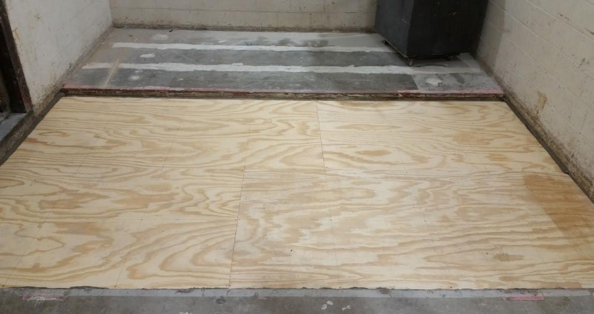
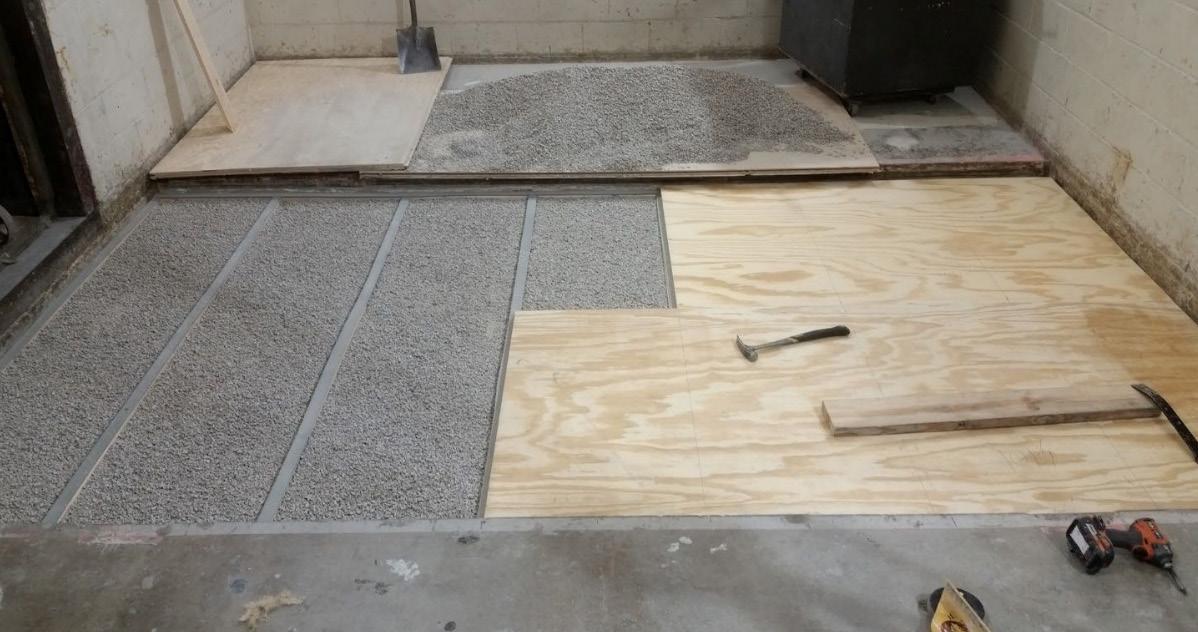
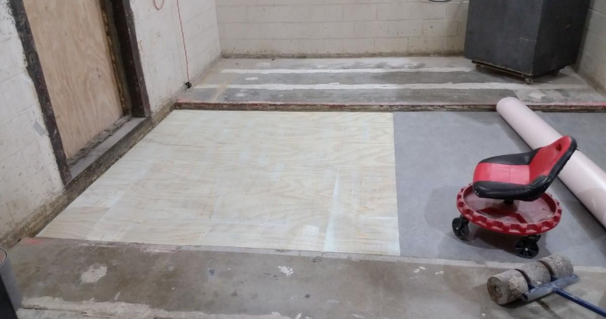
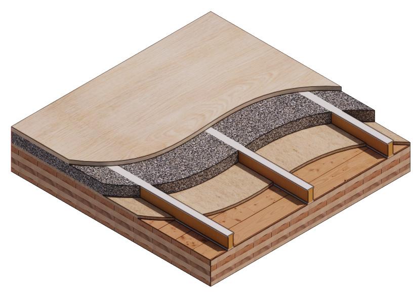
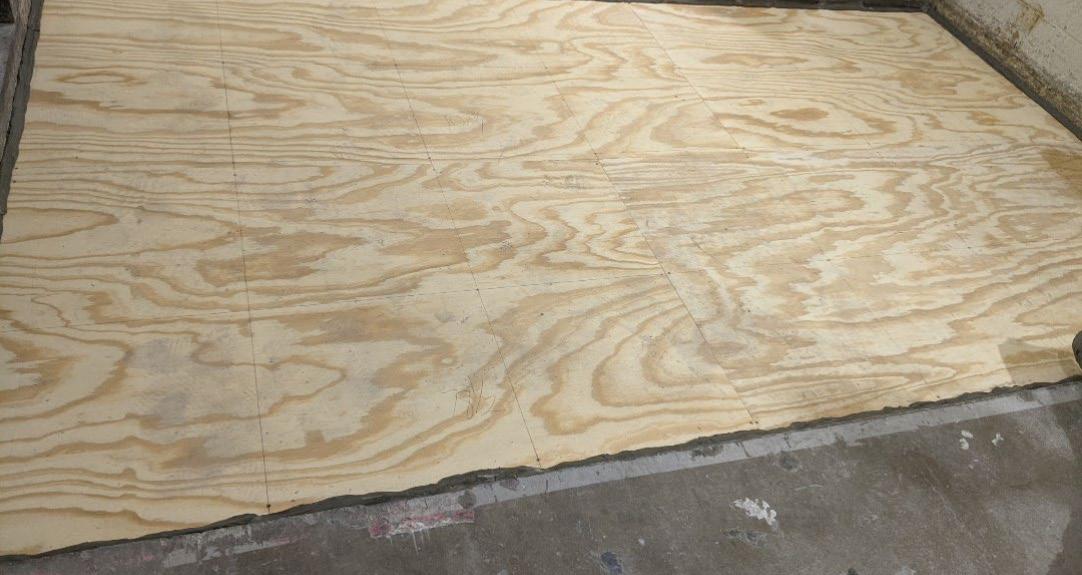
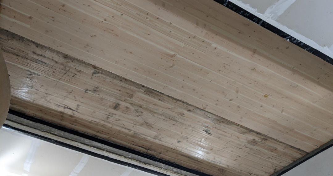
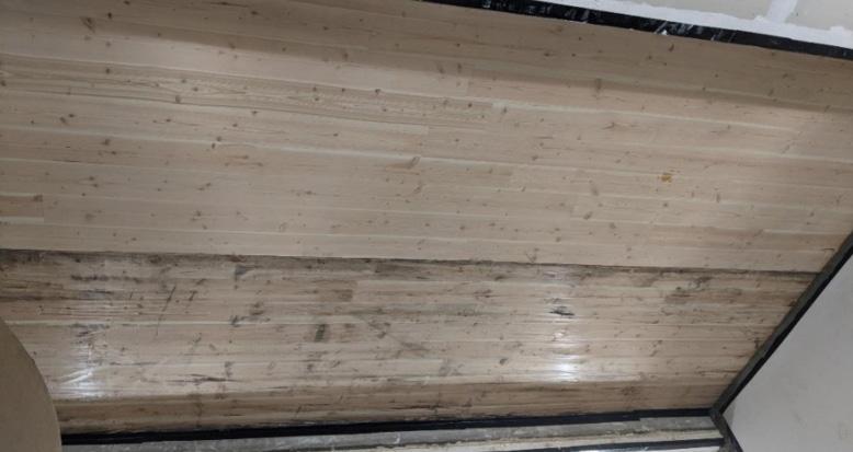
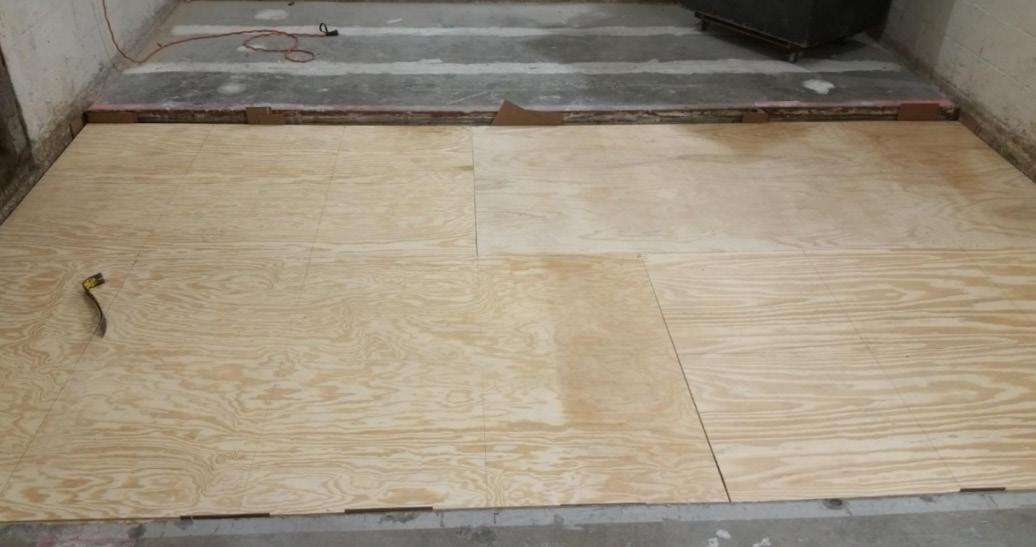
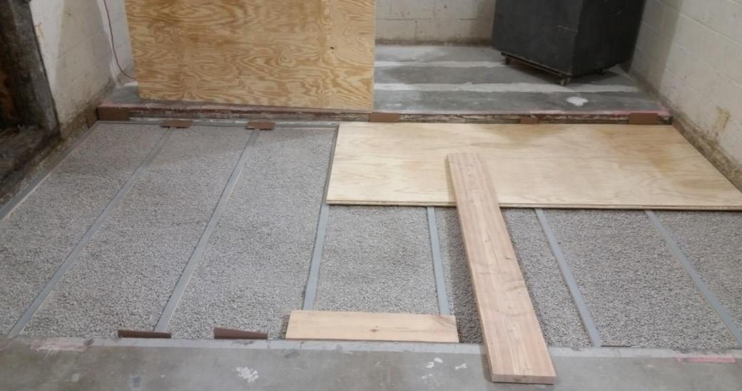
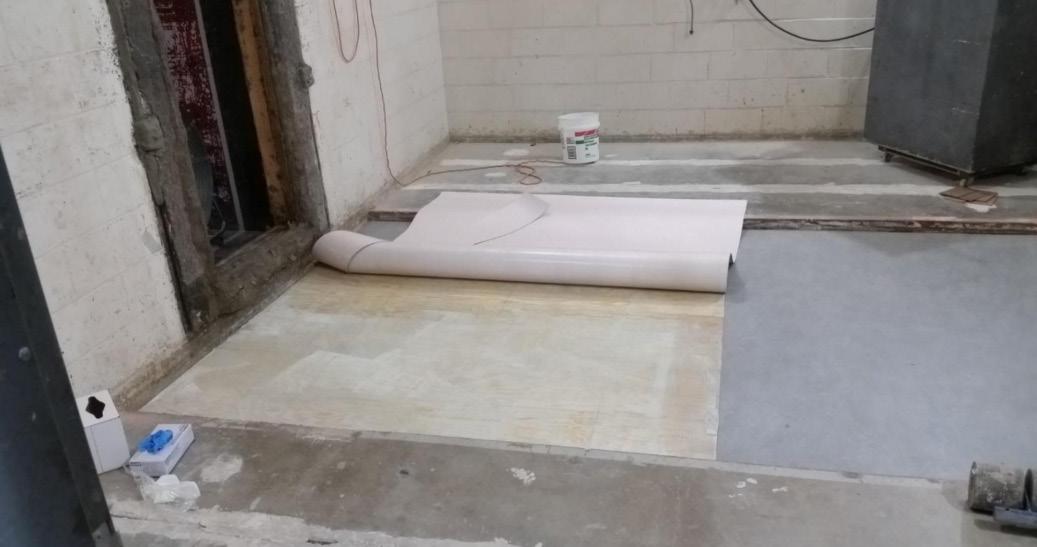
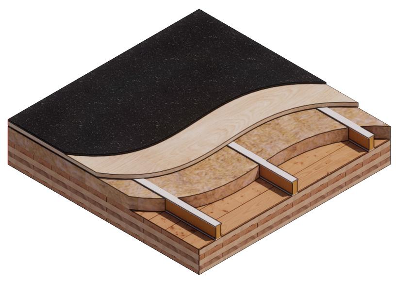
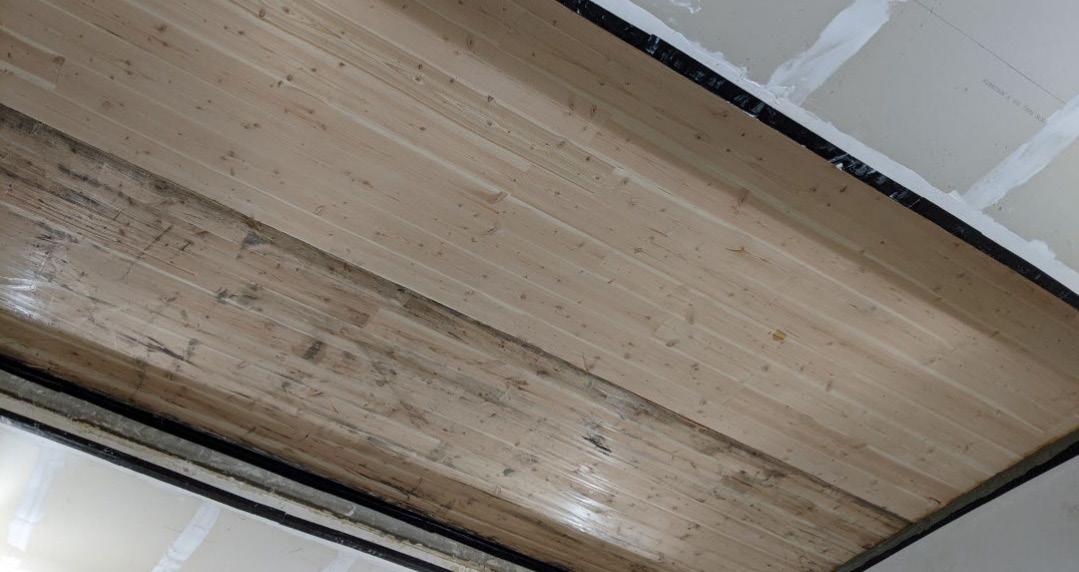
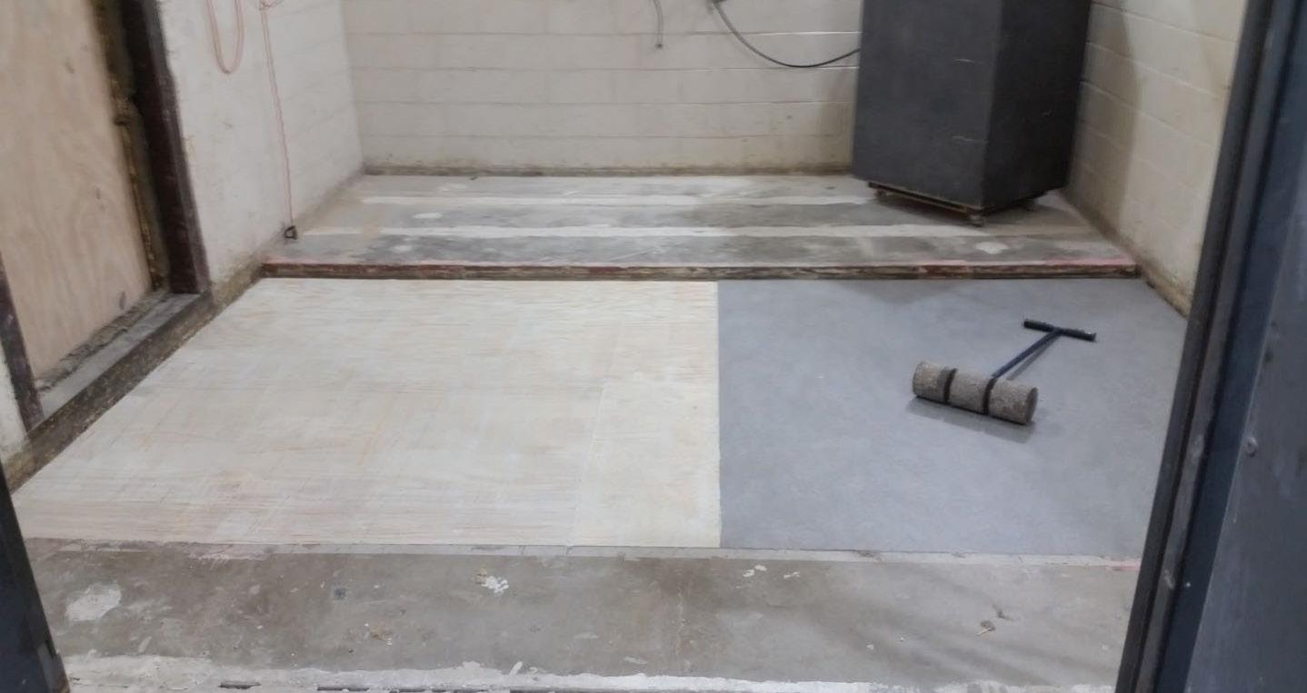
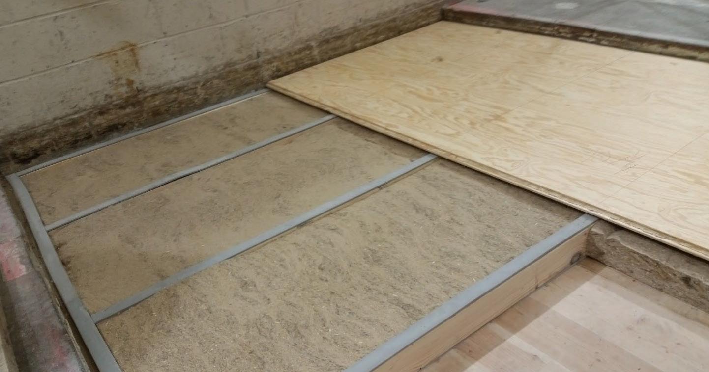
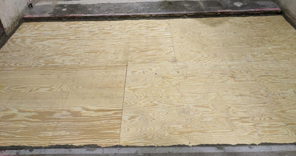
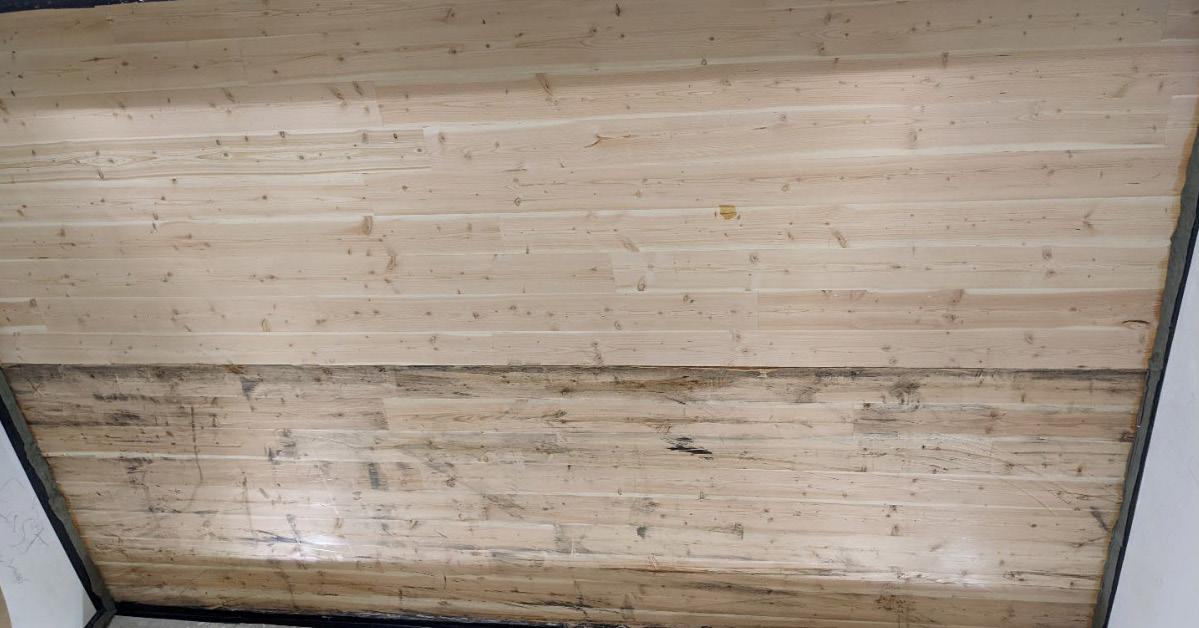
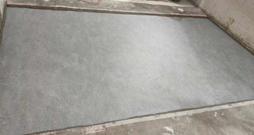
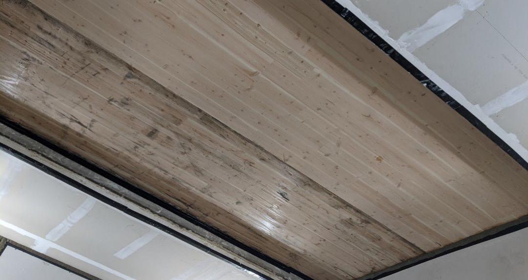
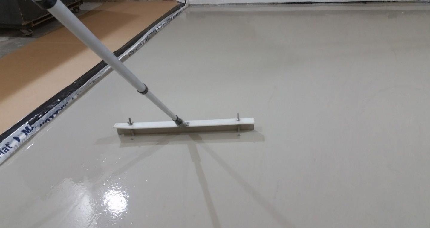
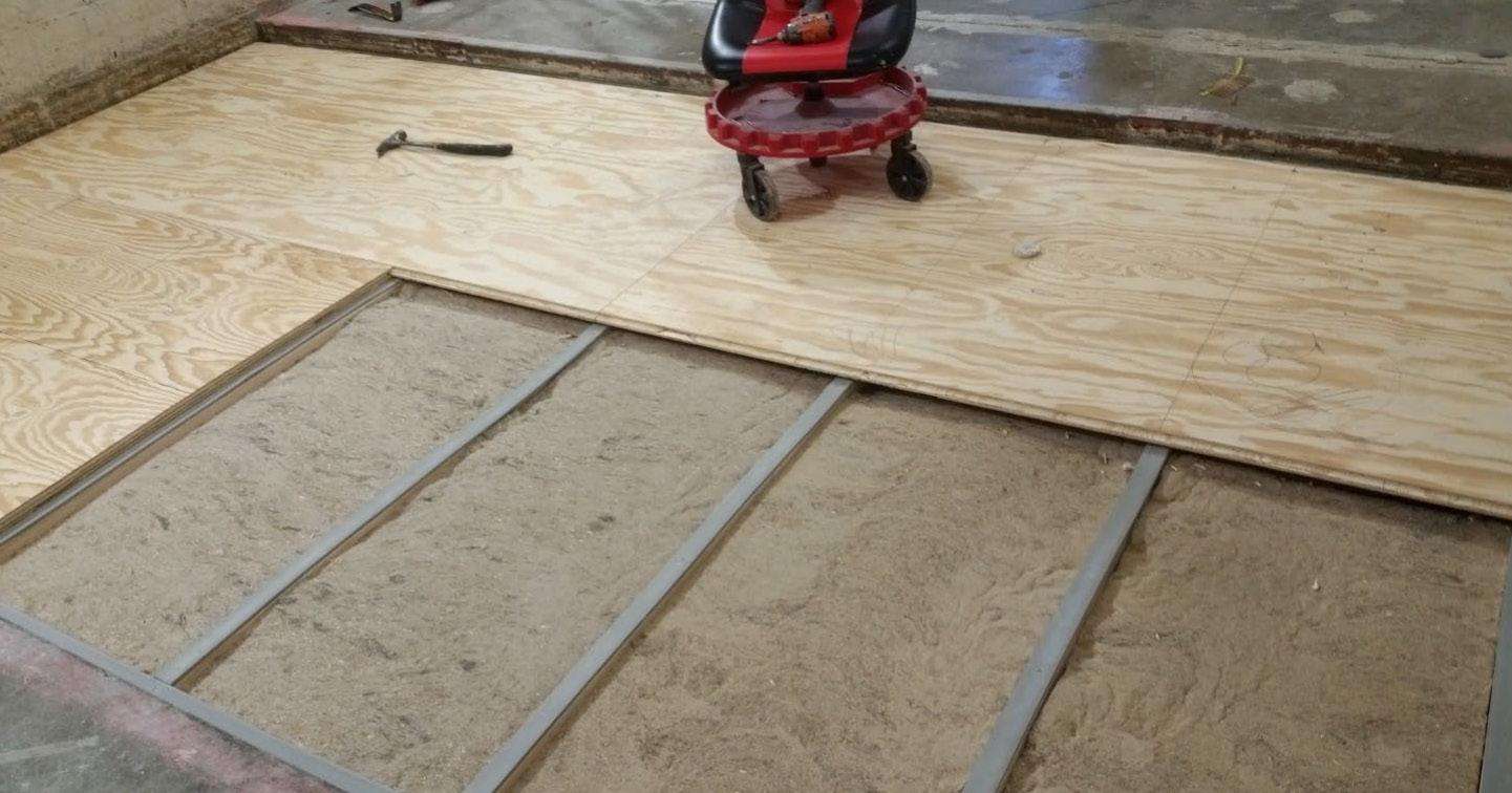
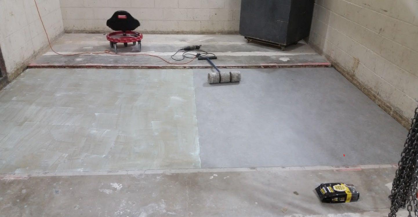
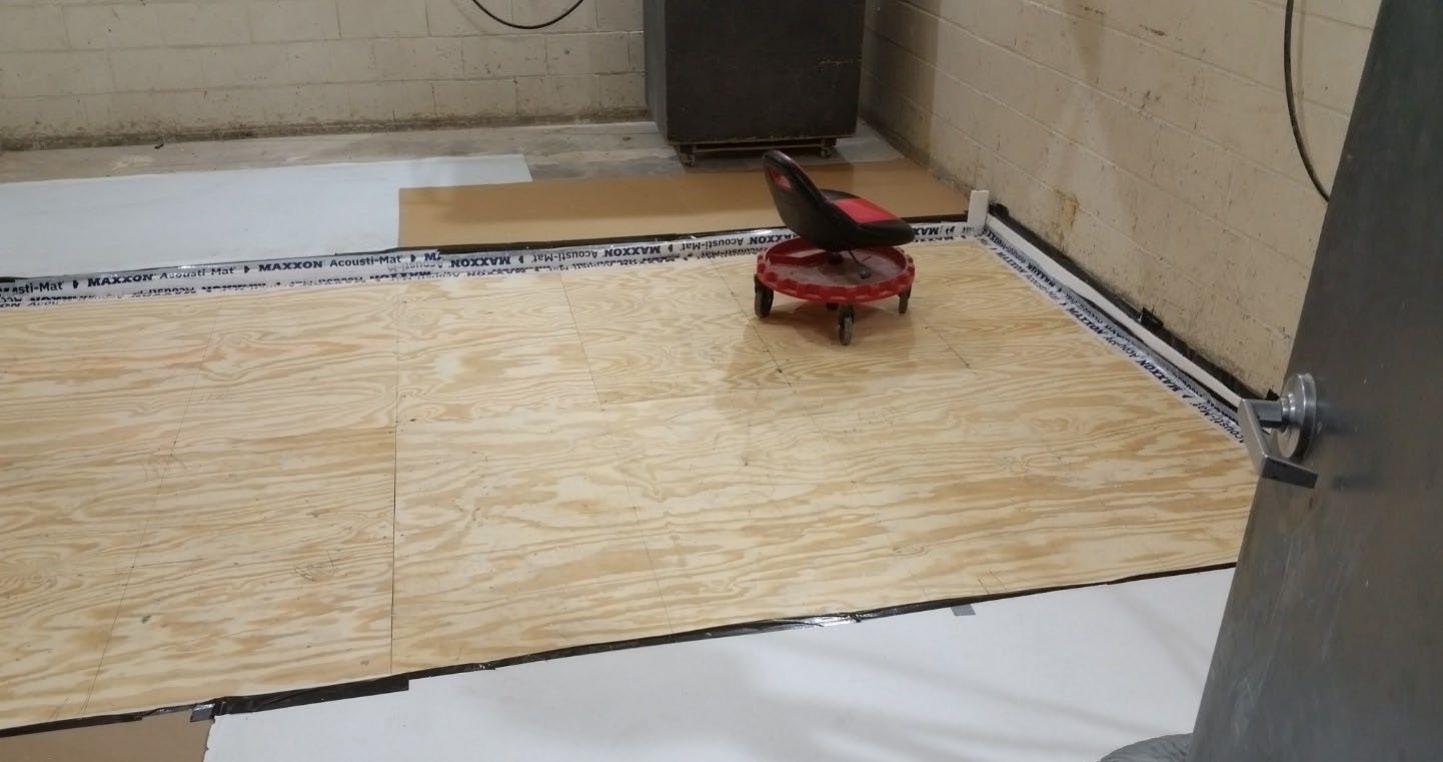
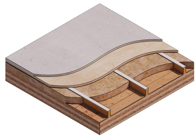
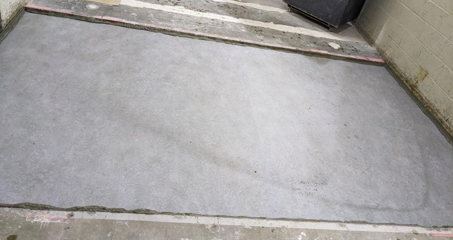
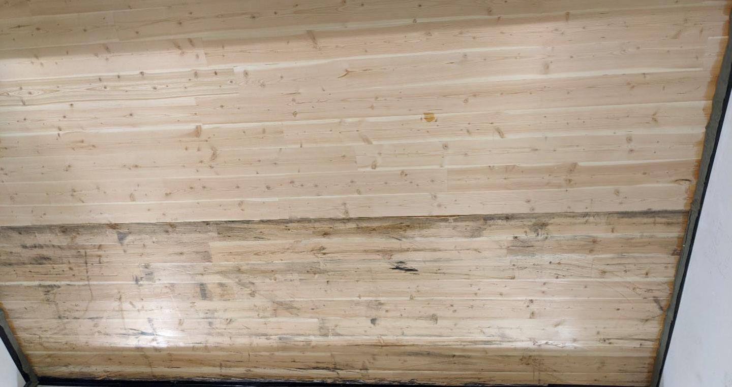
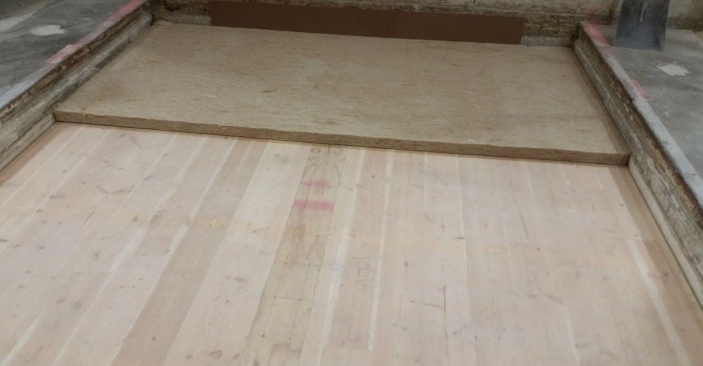
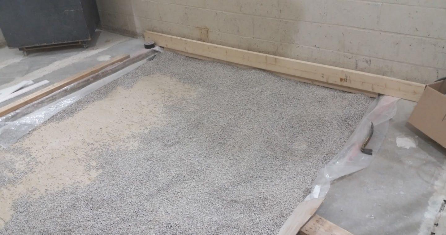
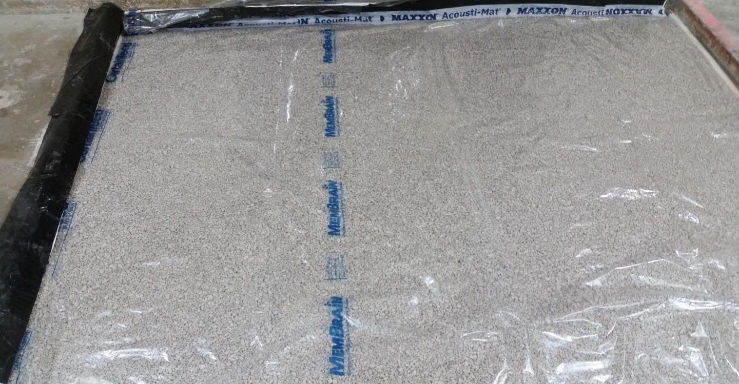
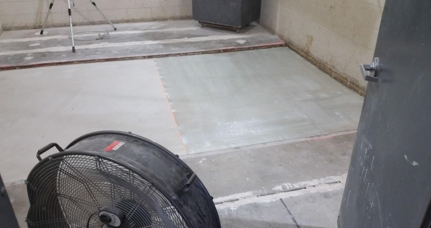
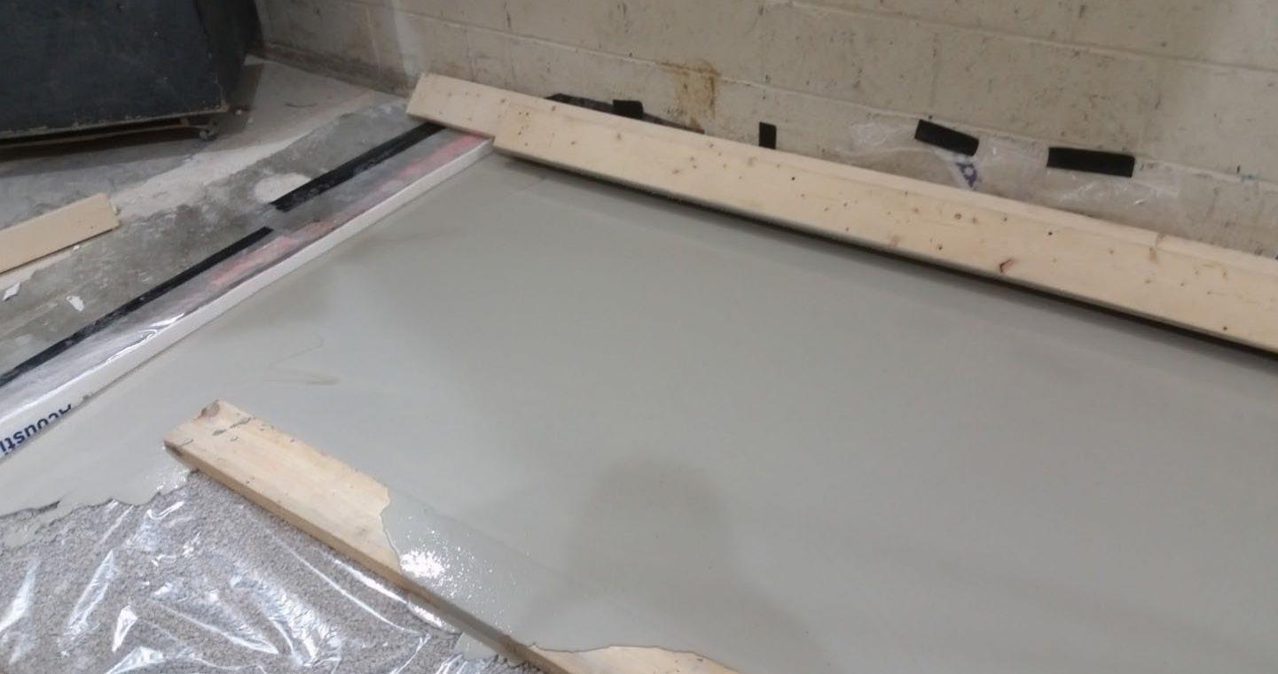
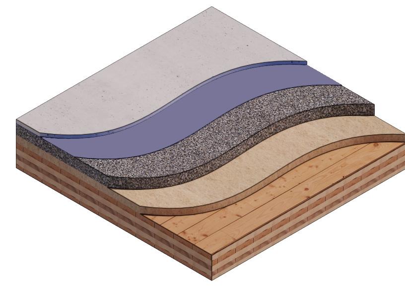
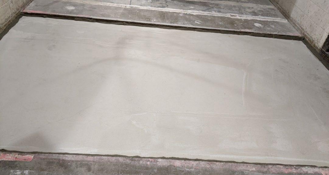
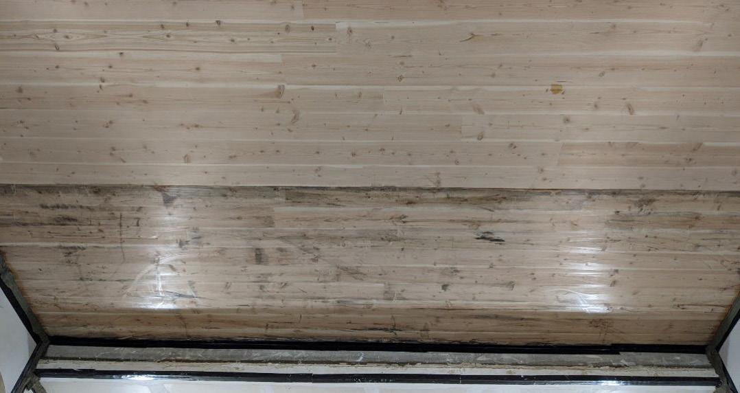
Tested assemblies were constructed with within the laboratory test chamber. The CLT layer of the tested assemblies was constructed of two panels, with the joint between panels running parallel to the long dimension. CLT panels were laid on 6” wide knee walls across the test opening and butted to one another without sealant or adhesive. Each of the two panels received a 3/4” x 3” rabbet on the top side where they abut, and were joined by a 3/4” x 6” plywood spline across the panel joint. This testing configuration is reflective of a typical configuration of CLT products within floor assemblies
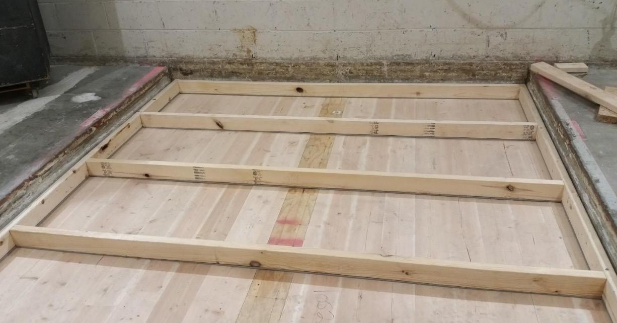
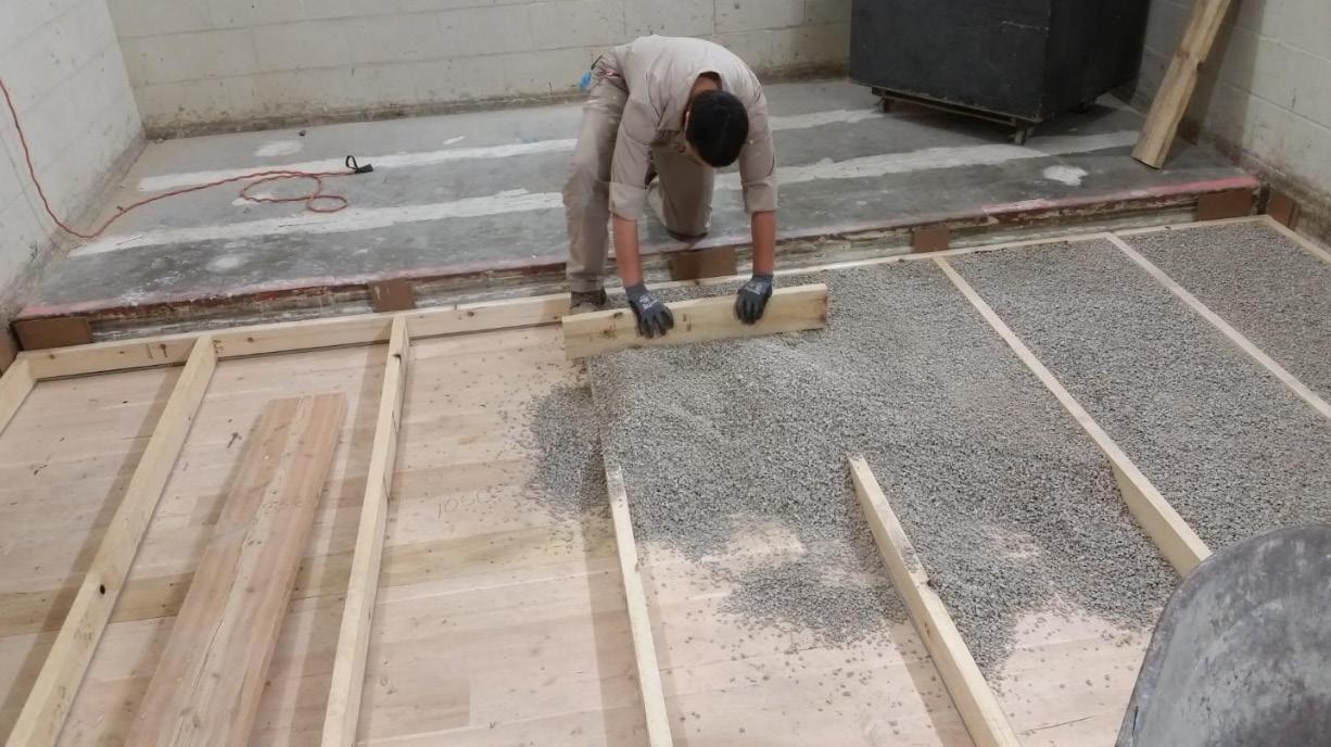
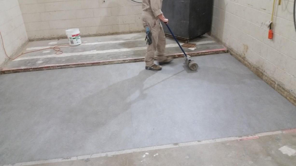
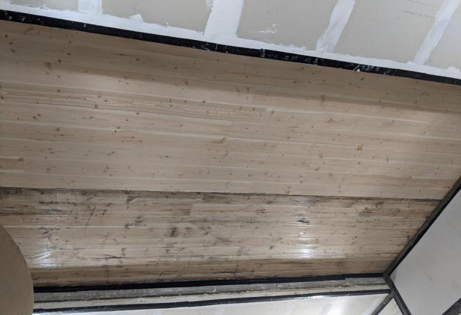
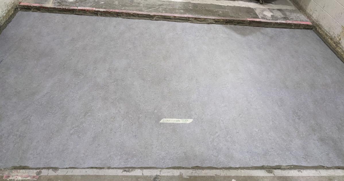
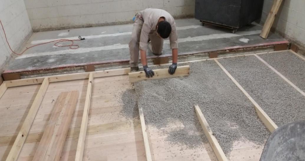
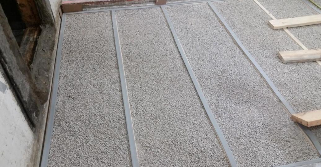
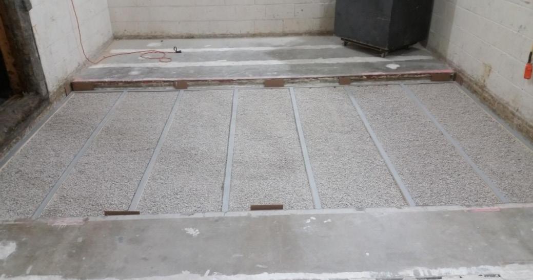
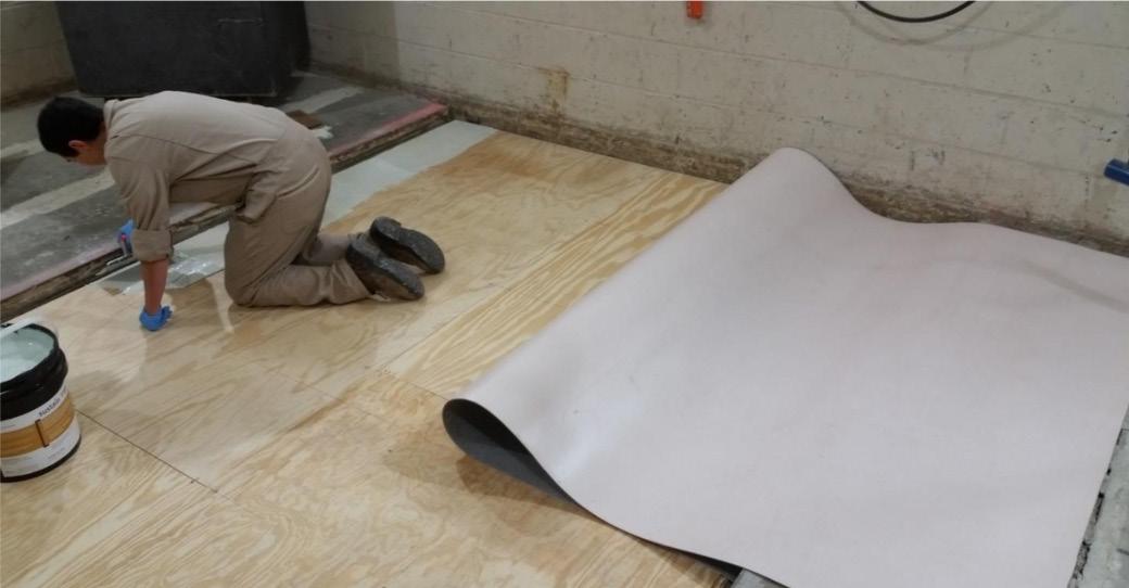
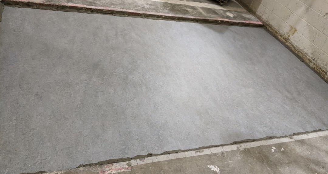
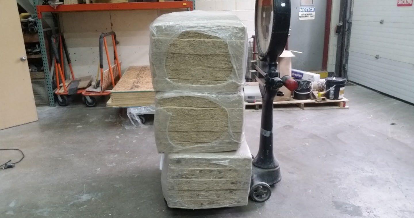
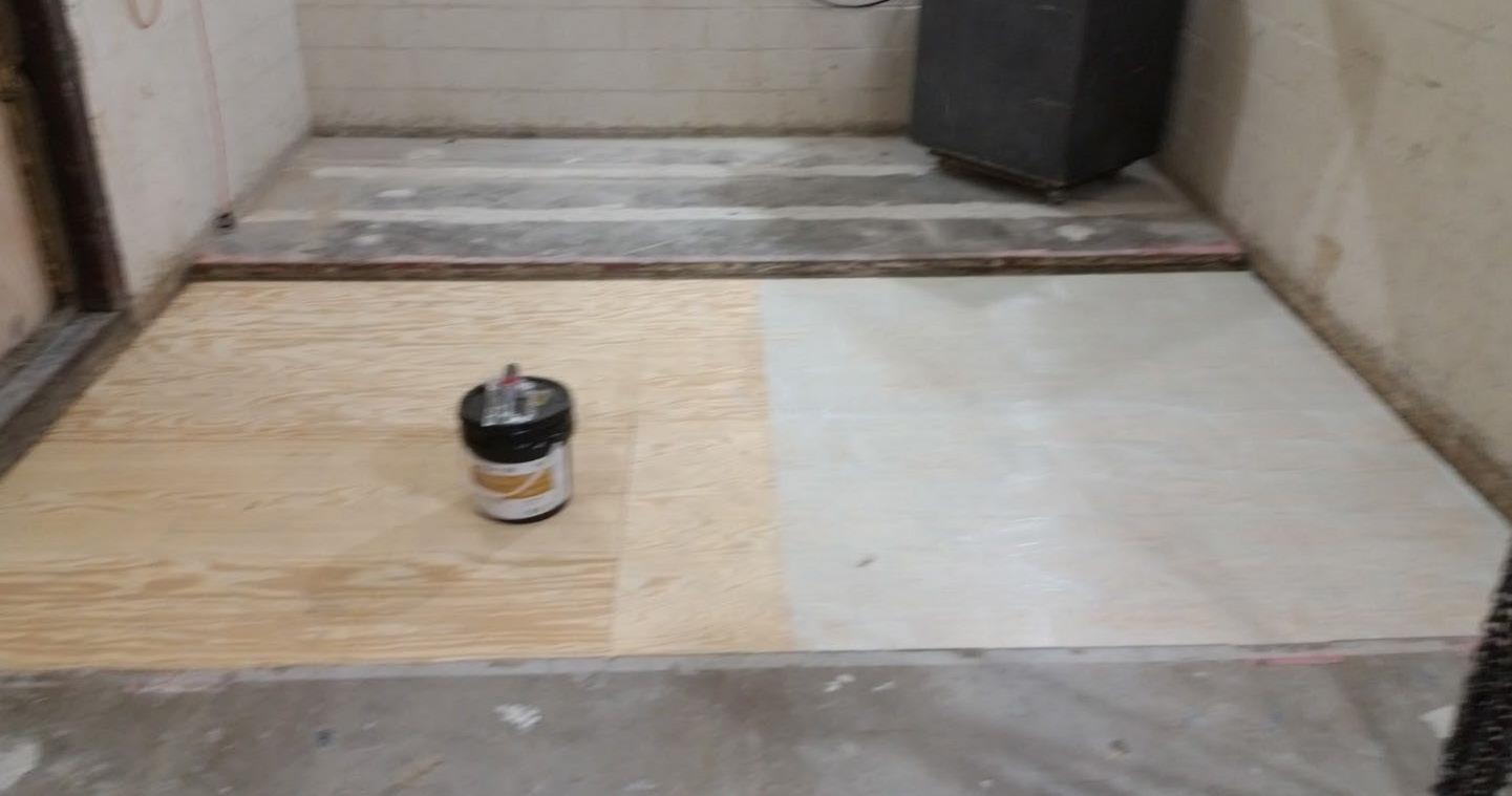
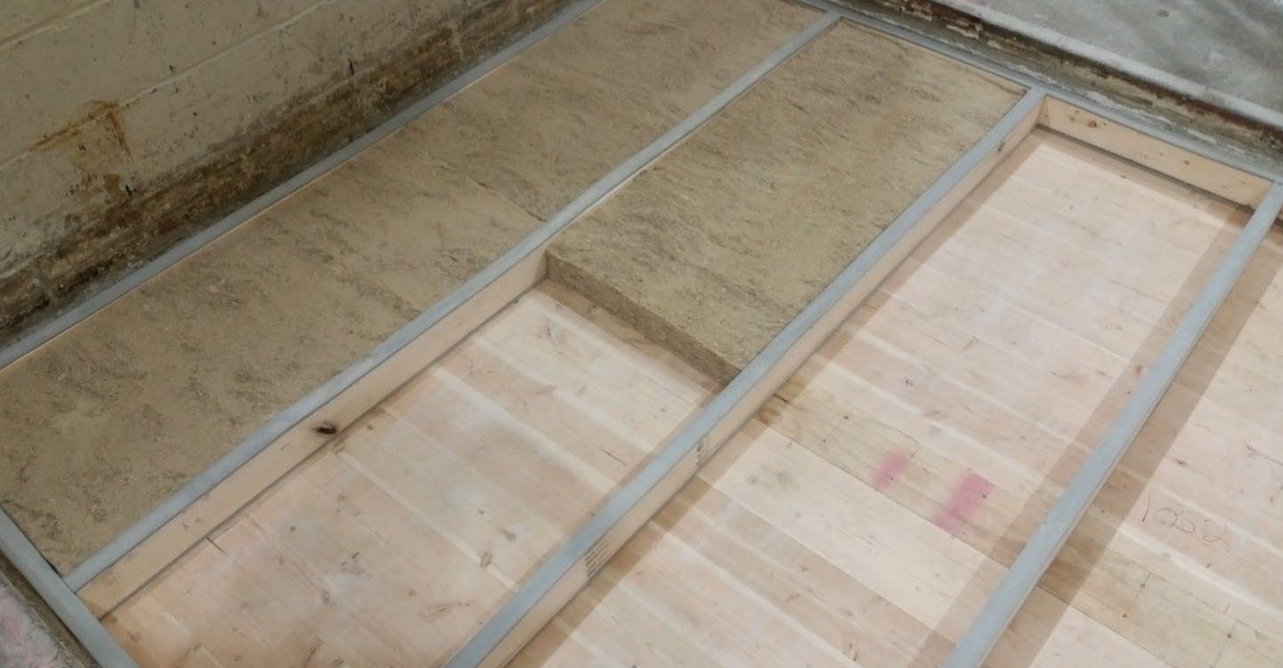
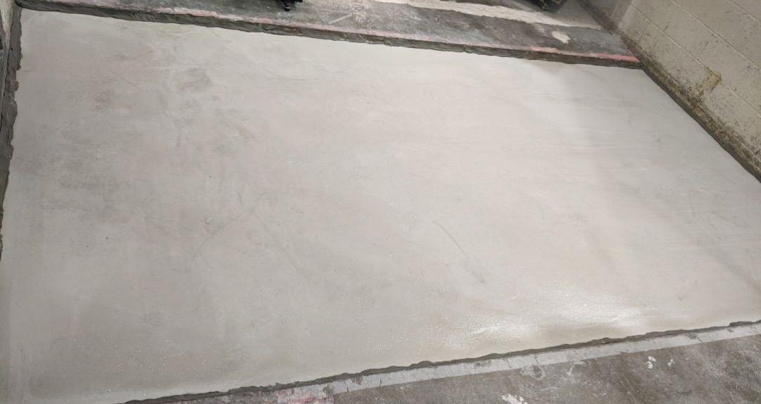
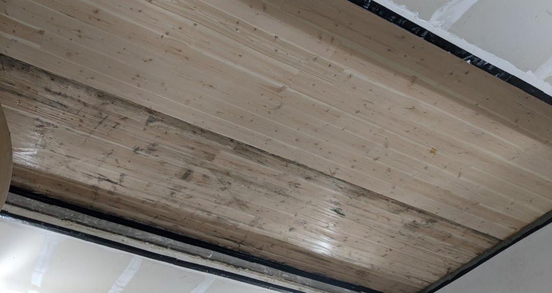
in field installations. Subsequent floor assembly layers were installed per manufacturer guidelines. See below photos of the floor assembly “F03” installation at the testing facility. These large-scale photos are a representative example of the installation process for the CLT installation of all floor assemblies, with subsequent layers unqiue to each assembly. For images of each assembly installation, see Section 03 below.
*All images in Figures 1-2 credit Riverbank Acoustical Laboratories
*All images in Figures 3-4 credit Riverbank Acoustical Laboratories

*All images in Figures 7-8 credit Riverbank Acoustical Laboratories
1. Hart, J., & Pomponi, F. (2020). More timber in construction: Unanswered Questions and future challenges. Sustainability, 12(8), 3473. https://doi.org/10.3390/su12083473
The following floor assemblies were tested by Riverbank Acoustical Laboratories™ is accredited by the U.S. Department of Commerce, National Institute of Standards and Technology (NIST) under the National Voluntary Laboratory Accreditation Program (NVLAP) as an ISO 17025:2005 Laboratory (NVLAP Lab Code: 1002270) and for this test procedure.
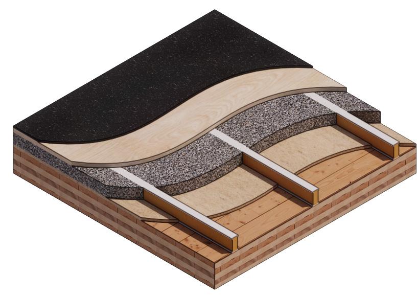
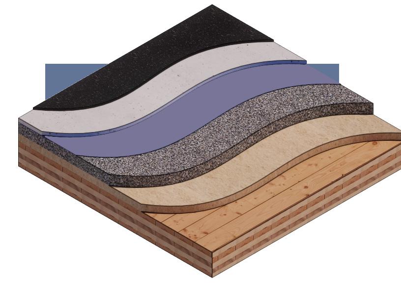
These assemblies were developed as described in Section 01, above. Emphasis was placed on the use of bio-based materials. Materials were also selected based on their ability to be installed and ease of disassembly, aiming to minimize the physically or chemically bonded layers that create a composite panel and might impact the assembly’s reuse potential at the end of its useful life.
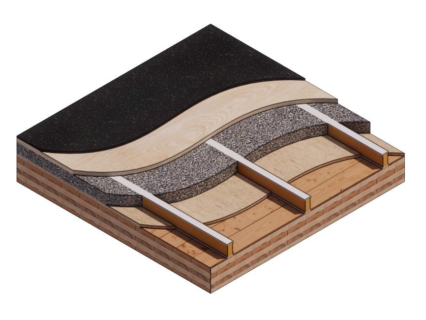
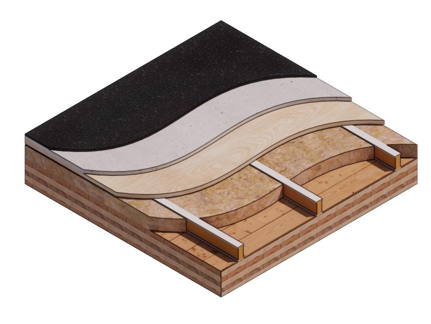
Marmoleum Decibel adhered with Sustain 1195
1 1/8” Plywood T&G Subfloor screwed 24” OC with #9x3”
3” of 3/8” Limestone Chip
Hempitecture 3/4” Hemp Fiber Board
2x4 Sleepers, 24” OC with Rothoblaas Piano B acoustic strips stapled top/bottom
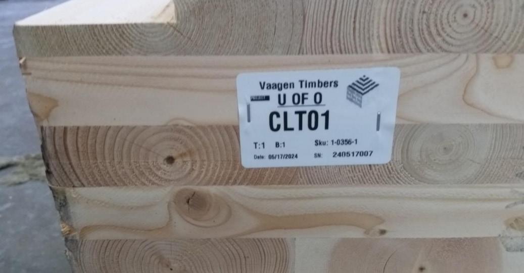
Vaagen Timbers 5-ply CLT 6.875”
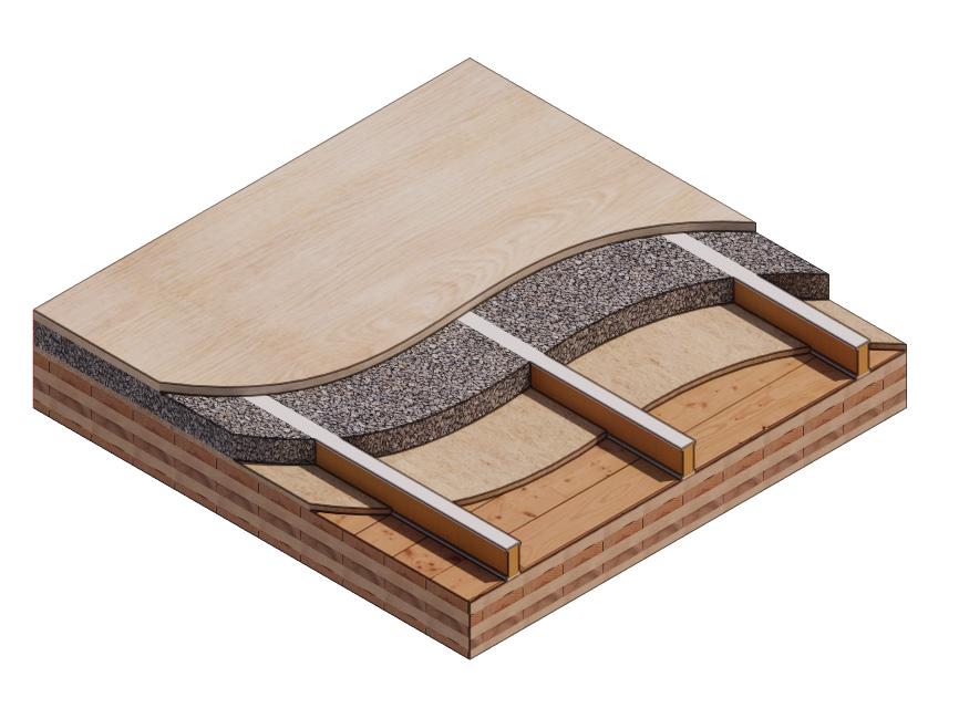
1 1/8” Plywood T&G Subfloor screwed 24” OC with #9x3”
3” of 3/8” Limestone Chip
Hempitecture 3/4” Hemp Fiber Board
2x4 Sleepers, 24” OC with Rothoblaas Piano B acoustic strips stapled top/bottom
Vaagen Timbers 5-ply CLT 6.875”
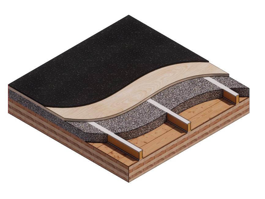
Marmoleum Decibel adhered with Sustain 1195
1 1/8” Plywood T&G Subfloor screwed 24” OC with #9x3”
3 3/4”of 3/8” Limestone Chip
2x4 Sleepers, 24” OC with Rothoblaas Piano B acoustic strips stapled top/bottom
Vaagen Timbers 5-ply CLT 6.875”
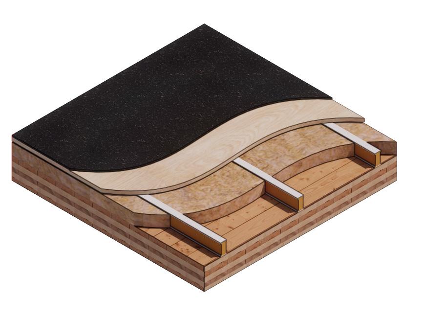
Marmoleum Decibel adhered with Sustain 1195
1 1/8” Plywood T&G Subfloor screwed 24” OC with #9x3”
HempWool Acoustibatt
3.5” hemp batt
2x4 Sleepers, 24” OC with Rothoblaas Piano B acoustic strips stapled top/bottom
Vaagen Timbers 5-ply CLT 6.875”
1 1/8” Plywood T&G Subfloor screwed 24” OC with #9x3”
HempWool Acoustibatt
3.5” hemp batt
2x4 Sleepers, 24” OC with Rothoblaas Piano B acoustic strips stapled top/bottom
Vaagen Timbers 5-ply CLT 6.875”
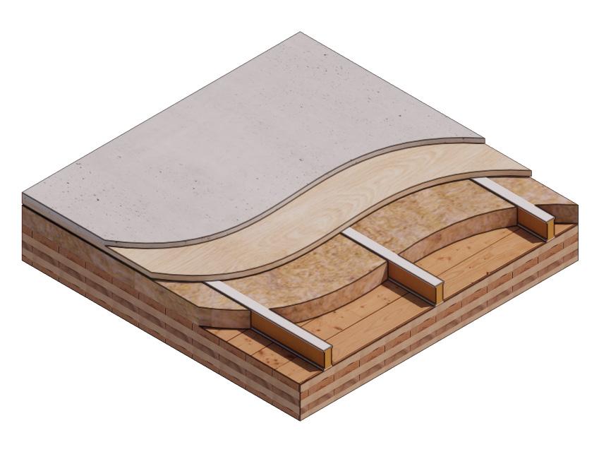
Marmoleum Decibel adhered with Sustain 1195
1” Maxxon Gypcrete 2000 Multifamily
1 1/8” Plywood T&G Subfloor screwed 24” OC with #9x3”
HempWool Acoustibatt 3.5” hemp batt
2x4 Sleepers, 24” OC with Rothoblaas Piano B acoustic strips stapled top/bottom
Vaagen Timbers 5-ply CLT 6.875”
1” Maxxon Gypcrete 2000
Multifamily
1 1/8” Plywood T&G Subfloor screwed 24” OC with #9x3”
3.5” hemp batt
2x4 Sleepers, 24” OC with Rothoblaas Piano B acoustic strips stapled top/bottom HempWool Acoustibatt
Vaagen Timbers 5-ply CLT 6.875”
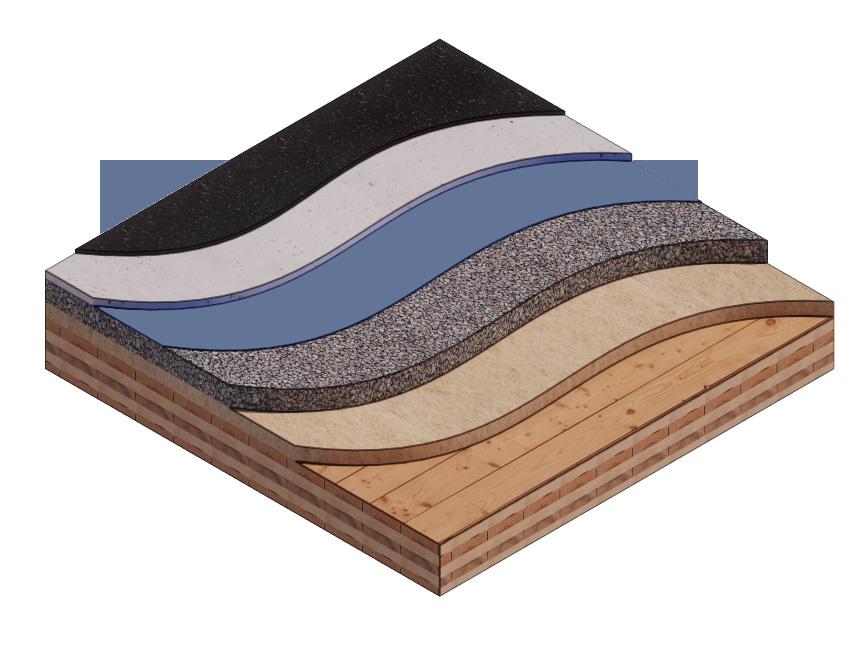
Marmoleum Decibel adhered with Sustain 1195
1” Maxxon Gypcrete 2000
Multifamily
Certainteed MemBrain Vapor Retarder
3”of 3/8” Limestone Chip
Hempitecture 2” Hemp Fiber Board
Vaagen Timbers 5-ply CLT 6.875”
1” Maxxon Gypcrete 2000
Multifamily
Certainteed MemBrain Vapor Retarder
3”of 3/8” Limestone Chip
2” Hemp Fiber Board (BOD: Hempitecture)
Vaagen Timbers 5-ply CLT 6.875”
Riverbank Acoustical Laboratories™ is accredited by the U.S. Department of Commerce, National Institute of Standards and Technology (NIST) under the National Voluntary Laboratory Accreditation Program (NVLAP) as an ISO 17025:2005 Laboratory (NVLAP Lab Code: 100227-0) and for this test procedure. The test reported in this document conformed explicitly with ASTM E492-09: “Standard Test Method for Laboratory Measurement of Impact Sound Transmission Through Floor-Ceiling Assemblies Using the Tapping Machine.” The single number rating of the specimen was calculated according to ASTM E989-18: “Standard Classification for Determination of Single-Number Metrics for Impact Noise.” A description of the measurement procedure and room specifications is available upon request.
The results presented in this report apply to the individual test specimen as described and assembled.
Certified ASTM lab testing reports can be found in the appendix.
SPECIMEN MEASUREMENTS
Dimensions: 2.44 m (96.0 in) wide by 3.86 m (152.0 in) high
Thickness: 0.31 m (12.125 in)
Weight: 2237.68 kg (4933.25 lbs)
Overall Area: 9.414 m2 (101.33 ft2)
Mass/Unit Area: 215.06 kg/m2 (44.05 lbs/ft2)
Opening Size: 4.27 m (14.0 ft) x 6.10 m (20.0 ft)
Filler Wall: Yes
Aperture Size: 2.44 m (96.0 in) wide by 3.86 m (152.0 in) high
Transmission Area: 9.414 m2 (101.33 ft2)
Sealed: Entire periphery (both sides) with dense mastic
Source Room Volume: 131.12 m3
Temperature: 22.8°C ±0.0°C
Relative Humidity: 62.5% ± 1.0%
Receive Room
Volume: 81.44 m3
Temperature: 22.2°C ± 0.0°C
Relative Humidity: 62.5% ± 1.0%
Requirements
Temperature: 22°C +/- 5°C, not more than 3°C change over all tests.
Relative Humidity: ≥ 30%, not more than +/- 3% change over all tests.
LAYER 1 - CROSS LAMINATED TIMBER (CLT)
Material: 5-Ply Cross-Laminated Timber
Dimensions: 2 panels @ 1219 mm (48 in.) by 4229 mm (166.5 in.)
Thickness: 171 mm (6.75 in.)
Overall Weight: 953.45 kg (2102 lbs)
Mass / Unit Volume: 539 kg/m3 (33.7 lbs/ft3)
Installation: CLT panels laid on 152 mm (6 in.) wide knee walls in test opening and butted to one another without sealant/adhesive. 3/4”x3”
Rabbet on top side of one edge of each panel where they butt allowing a loose plywood spline (above) to insert and join the two.
LAYER 2 - 3/4” CDX LOOSE SPLINE
Material: 3/4” x 6” plywood spline
Dimensions:
1 piece @ 151 mm (5.9375 in.) wide by 2438 mm (96 in.)
1 piece @ 151 mm (5.9375 in.) wide by 1791 mm (70.5 in.)
Thickness: 19 mm (0.75 in.)
Overall Weight: 6.46 kg (14.25 lbs)
Mass / Unit Length: 1.53 kg/m (1.03 lbs/ ft)
Installation: Set in Rabbets of both CLT’s and screwed in place.
Fasteners: WSV Bugle head sub-floor screws, length @ 76 mm (3 in.)
Fastener Spacing: 6” o.c. on a line 3” from each edge of the spline (Centered on the rabbet of the CLT)
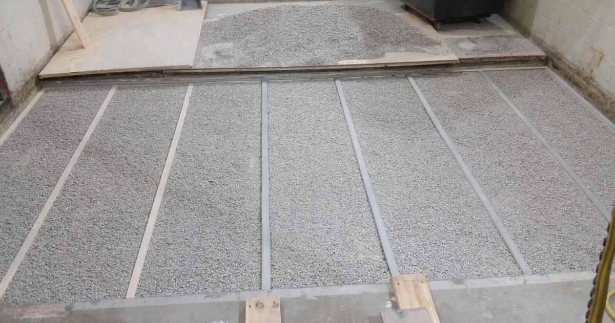
LAYER 3 - PIANO B 40/40 (LOWER LAYER)
Manufacturer: Rothoblaas
Dimensions:
2 strips @ 40 mm (1.5625 in.) wide by 4267 mm (168 in.) long
8 strips @ 2362 mm (93 in.) wide by 40 mm (1.5625 in.) long
Thickness: 6.76 mm (0.266 in.)
Overall Weight: 4.59 kg (10.125 lbs)
Mass/Unit Volume: 624 kg/m3 (40.00 lbs/ft3)
Installation: Fastened to underside of 2” x 4” wood sleepers with staples
Fasteners: Arrow staples, length @ 13 mm (0.5 in.)
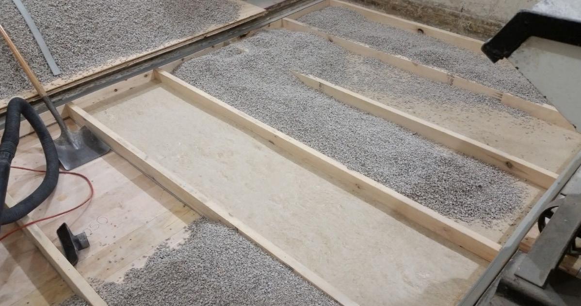
LAYER 4 - 2x4 SPF FRAMING SLEEPERS
Material: Nominal 2x4 framing lumber
Dimensions:
2 pieces @ 38 mm (1.5 in.) wide by 4255 mm (167.5 in. long
8 pieces @ 2369 mm (93.25 in.) wide by 38 mm (1.5 in.) long
Depth: 89 mm (3.5 in.)
Overall Weight: 49.33 kg (108.75 lbs)
Mass / Unit Length: 1.80 kg/m (1.21 lbs/ ft)
Installation: Sleepers laid over CLT, resting on lower layer Piano B 40/40. Longer sleepers parallel to CLT like a rim joist. Shorter sleepers set like floor joists between rim joists. Shorter sleepers spaced approx. 610 mm (24 in.) on center. Shorter sleepers fastened to longer sleepers with screws, 2 screws per connection point.
Fasteners: WSV Bugle head sub-floor screws, length @ 76 mm (3 in.)
LAYER 5 - PIANO B 40/40 (UPPER LAYER)
Manufacturer: Rothoblaas
Dimensions:
2 strips @ 40 mm (1.5625 in.) wide by 4267 mm (168 in.) long
8 strips @ 2362 mm (93 in.) wide by 40 mm (1.5625 in.) long
Thickness: 6.76 mm (0.266 in.)
Overall Weight: 4.59 kg (10.125 lbs)
Mass/Unit Volume: 624 kg/m3 (40.0 lbs/ft3)
Installation: Fastened to top of 2” x 4” wood sleepers with staples.
Fasteners: Arrow staples, length @ 13 mm (0.5 in.)
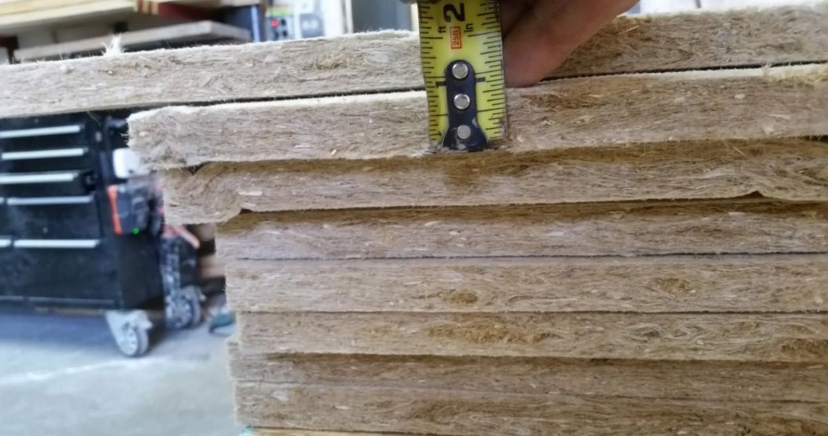
LAYER 6 - HEMPBOARD
Manufacturer: Hempitecture
Dimensions:
7 pieces @ 572 mm (22.5 in.) wide by 2369 mm (93.25 in.) long
Thickness: 19 mm (0.75in.)
Overall Weight: 24.38 kg (53.75 lbs)
Mass/Unit Volume: 135 kg/m3 (8.43 lbs/ ft3)
Installation: Friction fit between sleepers on top of CLT.
Material: CA-16 3/8” chip crushed limestone
Dimensions: 2438 mm (96 in.) wide by 4267 mm (168 in.) long, as installed
Depth: 70 mm (2.75 in.)
Overall Weight: 986.56 kg (2175 lbs)
Installation: Filled stone in above hemp board and between sleepers and used a screed to level to the top of the sleepers.
Material: T&G Plywood
Dimensions:
1 piece @ 1219 mm (48 in.) wide by 1829 mm (72 in.)
1 piece @ 1219 mm (48 in.) wide by 2438 mm (96 in.)
1 piece @ 1219 mm (48 in.) wide by 1822 mm (71.75 in.)
1 piece @ 1219 mm (48 in.) wide by 2432 mm (95.75 in.)
Thickness: 29 mm (1.125 in.)
Overall Weight: 170.66 kg (376.25 lbs)
Mass / Unit Volume: 575 kg/m3 (35.9 lbs/ft3)
Installation: Placed over upper layer Piano B 40/40 over sleepers. Fastened to sleepers through Piano B 40/40 with screws. Plywood piece joints staggered. Fasteners: WSV Bugle head sub-floor screws, length @ 76 mm (3 in.)
Fastener Spacing: 610 mm (24 in.) on center
Material: Sustain 1195 Sheet and Tile adhesive
Manufacturer: Forbo
Dimensions: Approx. 2438 mm (96 in.) by 4267 mm (168 in.) as installed
Overall Weight: 5.44 kg (12 lbs)
Mass / Unit Area: 0.52 kg/m2 (0.11 lbs/ ft2)
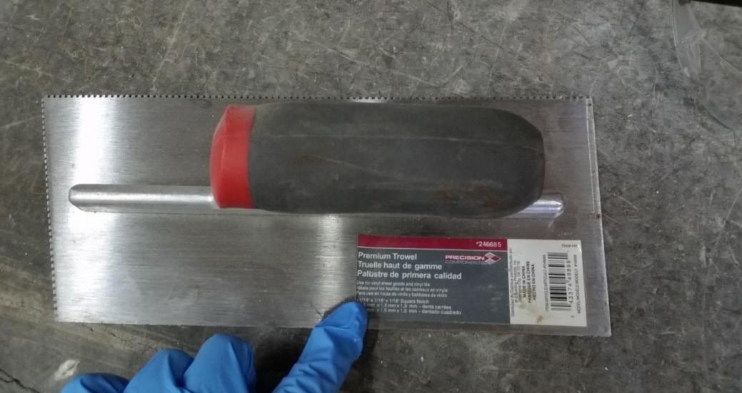
Installation: Troweled directly to plywood with a 1/16x1/16x1/16 square notch trowel
Once troweled, adhesive was left “open” for 15 min to allow it to “tack” before flooring was installed.
Material: Marmoleum Decibel
Manufacturer: Forbo
Dimensions: 2 pieces @ 2007 mm (79 in.) by 2464 mm (97 in.)
Thickness: 6 mm (0.25 in.)
Overall Weight: 32.21 kg (71 lbs)
Mass / Unit Volume: 482 kg/m3 (30.1 lbs/ft3)
Installation: Two (2) 79” segments perpendicular to Plywood 10” strip to complete. Joints staggered from parallel plywood joints by + 6”. Rolled with 100lb roller in each direction.
= FREQUENCY (1/3 OCTAVE BAND, CENTER), HERTZ
FREQ. = FREQUENCY, HERTZ Ln = NORMALIZED SOUND PRESSURE LEVEL, dB ΔLn = 95% UNCERTAINTY LIMIT FOR Ln, dB DEV. = DEVIATION FROM SHIFTED IIC COUNTOUR, dB IIC = IMPACT INSULATION CLASS
*Level corrected due to background noise per E492 SEC 10.2.2
**Level corrected due to background noise per E492 SEC 10.2.3

SPECIMEN MEASUREMENTS
Dimensions: 2.44 m (96.0 in) wide by 3.86 m (152.0 in) high
Thickness: 0.3 m (11.875 in)
Weight: 2200.03 kg (4850.25 lbs)
Overall Area: 9.414 m2 (101.33 ft2)
Mass/Unit Area: 211.44 kg/m2 (43.31 lbs/ft2)
Opening Size: 4.27 m (14.0 ft) x 6.10 m (20.0 ft)
Filler Wall: Yes
Aperture Size: 2.44 m (96.0 in) wide by
3.86 m (152.0 in) high
Transmission Area: 9.414 m2 (101.33 ft2)
Sealed: Entire periphery (both sides) with dense mastic
Source Room
Volume: 131.12 m3
Temperature: 23.1°C ±0.6°C
Relative Humidity: 60.5% ± 1.0%
Receive Room
Volume: 81.44 m3
Temperature: 22.5°C ± 0.6°C
Relative Humidity: 60.5% ± 1.0%
Requirements
Temperature: 22°C +/- 5°C, not more than 3°C change over all tests.
Relative Humidity: ≥ 30%, not more than +/- 3% change over all tests.
LAYER 1 - CROSS LAMINATED TIMBER (CLT)
Material: 5-Ply Cross-Laminated Timber
Dimensions: 2 panels @ 1219 mm (48 in.) by 4229 mm (166.5 in.)
Thickness: 171 mm (6.75 in.)
Overall Weight: 953.45 kg (2102 lbs)
Mass / Unit Volume: 539 kg/m3 (33.7 lbs/ft3)
Installation: CLT panels laid on 152 mm (6 in.) wide knee walls in test opening and butted to one another without sealant/adhesive. 3/4”x3” Rabbet on top side of one edge of each panel where they butt allowing a loose spline (above) to insert and join the two.
Material: 3/4” x 6” plywood spline
Dimensions:
1 piece @ 151 mm (5.9375 in.) wide by 2438 mm (96 in.)
1 piece @ 151 mm (5.9375 in.) wide by 1791 mm (70.5 in.)
Thickness: 19 mm (0.75 in.)
Overall Weight: 6.46 kg (14.25 lbs)
Mass / Unit Length: 1.53 kg/m (1.03 lbs/ ft)
Installation: Set in Rabbets of both CLT’s and screwed in place.
Fasteners: WSV Bugle head sub-floor screws, length @ 76 mm (3 in.)
Fastener Spacing: 6” o.c. on a line 3” from each edge of the spline (Centered on the rabbet of the CLT)
LAYER 3 - PIANO B 40/40 (LOWER LAYER)
Manufacturer: Rothoblaas
Dimensions: 2 strips @ 40 mm (1.5625 in.) wide by 4267 mm (168 in.) long
8 strips @ 2362 mm (93 in.) wide by 40 mm (1.5625 in.) long
Thickness: 6.76 mm (0.266 in.)
Overall Weight: 4.59 kg (10.125 lbs)
Mass/Unit Volume: 624 kg/m3 (40.00 lbs/ft3)
Installation: Fastened to underside of 2” x 4” wood sleepers with staples
Fasteners: Arrow staples, length @ 13 mm (0.5 in.)
LAYER 4 - 2x4 SPF FRAMING SLEEPERS
Material: Nominal 2x4 framing lumber
Dimensions:
2 pieces @ 38 mm (1.5 in.) wide by 4255 mm (167.5 in. long
8 pieces @ 2369 mm (93.25 in.) wide by 38 mm (1.5 in.) long
Depth: 89 mm (3.5 in.)
Overall Weight: 49.33 kg (108.75 lbs)
Mass / Unit Length: 1.80 kg/m (1.21 lbs/ ft)
Installation: Sleepers laid over CLT, resting on lower layer Piano B 40/40. Longer sleepers parallel to CLT like a rim joist. Shorter sleepers set like floor joists between rim joists. Shorter sleepers spaced approx. 610 mm (24 in.) on center. Shorter sleepers fastened to longer sleepers with screws, 2 screws per connection point.
Fasteners: WSV Bugle head sub-floor screws, length @ 76 mm (3 in.)
LAYER 5 - PIANO B 40/40 (UPPER LAYER)
Manufacturer: Rothoblaas
Dimensions:
2 strips @ 40 mm (1.5625 in.) wide by 4267 mm (168 in.) long
8 strips @ 2362 mm (93 in.) wide by 40 mm (1.5625 in.) long
Thickness: 6.76 mm (0.266 in.)
Overall Weight: 4.59 kg (10.125 lbs)
Mass/Unit Volume: 624 kg/m3 (40.0 lbs/ft3)
Installation: Fastened to top of 2” x 4” wood sleepers with staples.
Fasteners: Arrow staples, length @ 13 mm (0.5 in.)
LAYER 6 - HEMPBOARD
Manufacturer: Hempitecture
Dimensions:
7 pieces @ 572 mm (22.5 in.) wide by 2369 mm (93.25 in.) long
Thickness: 19 mm (0.75 in.)
Overall Weight: 24.38 kg (53.75 lbs)
Mass/Unit Volume: 135 kg/m3 (8.43 lbs/ ft3)
Installation: Friction fit between sleepers on top of CLT.
Material: CA-16 3/8” chip crushed limestone
Dimensions: 2438 mm (96 in.) wide by 4267 mm (168 in.) long, as installed
Depth: 70 mm (2.75 in.)
Overall Weight: 986.56 kg (2175 lbs)
Installation: Filled stone in above hemp board and between sleepers and used a screed to level to the top of the sleepers.
Material: T&G Plywood
Dimensions:
1 piece @ 1219 mm (48 in.) wide by 1829 mm (72 in.)
1 piece @ 1219 mm (48 in.) wide by 2438 mm (96 in.)
1 piece @ 1219 mm (48 in.) wide by 1822 mm (71.75 in.)
1 piece @ 1219 mm (48 in.) wide by 2432 mm (95.75 in.)
Thickness: 29 mm (1.125 in.)
Overall Weight: 170.66 kg (376.25 lbs)
Mass / Unit Volume: 575 kg/m3 (35.9 lbs/ft3)
Installation: Placed over upper layer Piano B 40/40 over sleepers. Fastened to sleepers through Piano B 40/40 with screws. Plywood piece joints staggered. Fasteners: WSV Bugle head sub-floor screws, length @ 76 mm (3 in.)
Fastener Spacing: 610 mm (24 in.) on center
= FREQUENCY (1/3 OCTAVE BAND, CENTER), HERTZ
in
SPECIMEN MEASUREMENTS
Dimensions: 2.44 m (96.0 in) wide by 3.86 m (152.0 in) high
Thickness: 0.31 m (12.125 in)
Weight: 2493.96 kg (5498.25 lbs)
Overall Area: 9.414 m2 (101.33 ft2)
Mass/Unit Area: 264.92 kg/m2 (54.26 lbs/ft2)
Opening Size: 4.27 m (14.0 ft) x 6.10 m (20.0 ft)
Filler Wall: Yes
Aperture Size: 2.44 m (96.0 in) wide by 3.86 m (152.0 in) high
Transmission Area: 9.414 m2 (101.33 ft2)
Sealed: Entire periphery (both sides) with dense mastic
Source Room Volume: 131.12 m3
Temperature: 22.8°C ±0.0°C
Relative Humidity: 61.0% ± 0.0%
Receive Room
Volume: 81.44 m3
Temperature: 21.1°C ± 0
Relative Humidity: 61.0% ± 0.0%
Requirements
Temperature: 22°C +/- 5°C, not more than 3°C change over all tests.
Relative Humidity: ≥ 30%, not more than +/- 3% change over all tests.
LAYER 1 - CROSS LAMINATED TIMBER (CLT)
Material: 5-Ply Cross-Laminated Timber
Dimensions: 2 panels @ 1219 mm (48 in.) by 4229 mm (166.5 in.)
Thickness: 171 mm (6.75 in.)
Overall Weight: 953.45 kg (2102 lbs)
Mass / Unit Volume: 539 kg/m3 (33.7 lbs/ft3)
Installation: CLT panels laid on 152 mm (6 in.) wide knee walls in test opening and butted to one another without sealant/adhesive. 3/4”x3” Rabbet on top side of one edge of each panel where they butt allowing a loose spline (below) to insert and join the two.
LAYER 2 - 3/4” CDX LOOSE SPLINE
Material: 3/4” x 6” plywood spline
Dimensions:
1 piece @ 151 mm (5.9375 in.) wide by 2438 mm (96 in.)
1 piece @ 151 mm (5.9375 in.) wide by 1791 mm (70.5 in.)
Thickness: 19 mm (0.75 in.)
Overall Weight: 6.46 kg (14.25 lbs)
Mass / Unit Length: 1.53 kg/m (1.03 lbs/ ft)
Installation: Set in Rabbets of both CLT’s and screwed in place.
Fasteners: WSV Bugle head sub-floor screws, length @ 76 mm (3 in.)
Fastener Spacing: 6” o.c. on a line 3” from each edge of the spline (Centered on the rabbet of the CLT)
LAYER 3- PIANO B 40/40 (LOWER LAYER)
Manufacturer: Rothoblaas
Dimensions: 2 strips @ 40 mm (1.5625 in.) wide by 4267 mm (168 in.) long 8 strips @ 2362 mm (93 in.) wide by 40 mm (1.5625 in.) long
Thickness: 6.76 mm (0.266 in.)
Overall Weight: 4.59 kg (10.125 lbs)
Mass/Unit Volume: 624 kg/m3 (40.00 lbs/ft3)
Installation: Fastened to underside of 2” x 4” wood sleepers with staples
Fasteners: Arrow staples, length @ 13 mm (0.5 in.)
4 - 2x4 SPF FRAMING
Material: Nominal 2x4 framing lumber
Dimensions:
2 pieces @ 38 mm (1.5 in.) wide by 4255 mm (167.5 in. long
8 pieces @ 2369 mm (93.25 in.) wide by 38 mm (1.5 in.) long
Depth: 89 mm (3.5 in.)
Overall Weight: 49.33 kg (108.75 lbs)
Mass / Unit Length: 1.80 kg/m (1.21 lbs/ ft)
Installation: Sleepers laid over CLT, resting on lower layer Piano B 40/40. Longer sleepers parallel to CLT like a rim joist. Shorter sleepers set like floor joists between rim joists. Shorter sleepers spaced approx. 610 mm (24 in.) on center. Shorter sleepers fastened to longer sleepers with screws, 2 screws per connection point.
Fasteners: WSV Bugle head sub-floor screws, length @ 76 mm (3 in.)
LAYER 5 - PIANO B 40/40 (UPPER LAYER)
Manufacturer: Rothoblaas
Dimensions:
2 strips @ 40 mm (1.5625 in.) wide by 4267 mm (168 in.) long
8 strips @ 2362 mm (93 in.) wide by 40 mm (1.5625 in.) long
Thickness: 6.76 mm (0.266 in.)
Overall Weight: 4.59 kg (10.125 lbs)
Mass / Unit Volume: 624 kg/m3 (40.0 lbs/ft3)
Installation: Fastened to top of 2” x 4” wood sleepers with staples.
Fasteners: Arrow staples, length @ 13 mm (0.5 in.)
LAYER 6 - CRUSHED LIMESTONE
Material: CA-16 3/8” chip crushed limestone
Dimensions: 2438 mm (96 in.) wide by 4267 mm (168 in.) long, as installed
Depth: 95 mm (3.75 in.)
Overall Weight: 1261.89 kg (2782 lbs)
Installation: Filled stone in between sleepers and used a screed to level to the top of the sleepers.
Material: T&G Plywood
Dimensions:
1 piece @ 1219 mm (48 in.) wide by 1829 mm (72 in.)
1 piece @ 1219 mm (48 in.) wide by 2438 mm (96 in.)
1 piece @ 1219 mm (48 in.) wide by 1813 mm (71.375 in.)
1 piece @ 1219 mm (48 in.) wide by 2426 mm (95.5 in.)
Thickness: 29 mm (1.125 in.)
Overall Weight: 176.33 kg (388.75 lbs)
Mass / Unit Volume: 595 kg/m3 (37.1 lbs/ft3)
Installation: Placed over upper layer Piano B 40/40 over sleepers. Fastened to sleepers through Piano B 40/40 with screws. Plywood piece joints staggered. Fasteners: WSV Bugle head sub-floor screws, length @ 76 mm (3 in.)
Fastener Spacing: 610 mm (24 in.) on center
Material: Sustain 1195 Sheet and Tile adhesive
Manufacturer: Forbo
Dimensions: Approx. 2438 mm (96 in.) by 4267 mm (168 in.) as installed
Overall Weight: 4.54 kg (10 lbs)
Mass / Unit Area: 0.44 kg/m2 (0.09 lbs/ ft2)
Installation: Troweled directly to plywood with a 1/16x1/16x1/16 square notch trowel
Once troweled, adhesive was left “open” for 7-10 min to allow it to “tack” before flooring was installed.
Material: Marmoleum Decibel
Manufacturer: Forbo
Dimensions: 2 pieces @ 2007 mm (79
in.) by 2464 mm (97 in.)
Thickness: 6 mm (0.25 in.)
Overall Weight: 32.77 kg (72.25 lbs)
Mass / Unit Volume: 522 kg/m3 (32.6 lbs/ft3)
Installation: Two (2) 79” segments perpendicular to Plywood 10” strip to complete. Joints staggered from parallel plywood joints by + 6”. Rolled with 100lb roller in each direction.
= FREQUENCY (1/3 OCTAVE BAND, CENTER), HERTZ
= DEVIATION FROM SHIFTED IIC COUNTOUR, dB IIC = IMPACT INSULATION CLASS *Level corrected due to background noise per E492 SEC 10.2.2 **Level corrected due to background noise per E492 SEC 10.2.3

SPECIMEN MEASUREMENTS
Dimensions: 2.44 m (96.0 in) wide by 3.86 m (152.0 in) high
Thickness: 0.31 m (12.125 in)
Weight: 1264.73 kg (2788.25 lbs)
Overall Area: 9.414 m2 (101.33 ft2)
Mass/Unit Area: 121.55 kg/m2 (24.90 lbs/ft2)
Opening Size: 4.27 m (14.0 ft) x 6.10 m (20.0 ft)
Filler Wall: Yes
Aperture Size: 2.44 m (96.0 in) wide by 3.86 m (152.0 in) high
Transmission Area: 9.414 m2 (101.33 ft2)
Sealed: Entire periphery (both sides) with dense mastic
Source Room
Volume: 131.12 m3
Temperature: 23.3°C ±0.0°C
Relative Humidity: 60.0% ± 0.0%
Receive Room
Volume: 81.44 m3
Temperature: 22.2°C ± 0.0°C
Relative Humidity: 62.0% ± 0.0%
Requirements
Temperature: 22°C +/- 5°C, not more than 3°C change over all tests. Relative Humidity: ≥ 30%, not more than +/- 3% change over all tests.
LAYER 1 - CROSS LAMINATED TIMBER (CLT)
Material: 5-Ply Cross-Laminated Timber
Dimensions: 2 panels @ 1219 mm (48 in.) by 4229 mm (166.5 in.)
Thickness: 171 mm (6.75 in.)
Overall Weight: 953.45 kg (2102 lbs)
Mass / Unit Volume: 539 kg/m3 (33.7 lbs/ft3)
Installation: CLT panels laid on 152 mm (6 in.) wide knee walls in test opening and butted to one another without sealant/adhesive. 3/4”x3” Rabbet on top side of one edge of each panel where they butt allowing a loose spline (below) to insert and join the two.
LAYER 2 - 3/4” CDX LOOSE SPLINE
Material: 3/4” x 6” plywood spline
Dimensions:
1 piece @ 151 mm (5.9375 in.) wide by 2438 mm (96 in.)
1 piece @ 151 mm (5.9375 in.) wide by 1791 mm (70.5 in.)
Thickness: 19 mm (0.75 in.)
Overall Weight: 6.46 kg (14.25 lbs)
Mass / Unit Length: 1.53 kg/m (1.03 lbs/ ft)
Installation: Set in Rabbets of both CLT’s and screwed in place.
Fasteners: WSV Bugle head sub-floor screws, length @ 76 mm (3 in.)
Fastener Spacing: 6” o.c. on a line 3” from each edge of the spline (Centered on the rabbet of the CLT)
LAYER 3 - PIANO B 40/40 (LOWER LAYER)
Manufacturer: Rothoblaas
Dimensions:
2 strips @ 40 mm (1.5625 in.) wide by 4267 mm (168 in.) long
8 strips @ 2362 mm (93 in.) wide by 40 mm (1.5625 in.) long
Thickness: 6.76 mm (0.266 in.)
Overall Weight: 4.59 kg (10.125 lbs)
Mass/Unit Volume: 624 kg/m3 (40.00 lbs/ft3)
Installation: Fastened to underside of 2” x 4” wood sleepers with staples
Fasteners: Arrow staples, length @ 13 mm (0.5 in.)
LAYER 4 - 2x4 SPF FRAMING SLEEPERS
Material: Nominal 2x4 framing lumber
Dimensions:
2 pieces @ 38 mm (1.5 in.) wide by 4255 mm (167.5 in. long
8 pieces @ 2369 mm (93.25 in.) wide by 38 mm (1.5 in.) long
Depth: 89 mm (3.5 in.)
Overall Weight: 49.33 kg (108.75 lbs)
Mass / Unit Length: 1.80 kg/m (1.21 lbs/ ft)
Installation: Sleepers laid over CLT, resting on lower layer Piano B 40/40. Longer sleepers parallel to CLT like a rim joist. Shorter sleepers set like floor joists between rim joists. Shorter sleepers spaced approx. 610 mm (24 in.) on center. Shorter sleepers fastened to longer sleepers with screws, 2 screws per connection point.
Fasteners: WSV Bugle head sub-floor screws, length @ 76 mm (3 in.)
LAYER 5 - PIANO B 40/40 (UPPER LAYER)
Manufacturer: Rothoblaas
Dimensions:
2 strips @ 40 mm (1.5625 in.) wide by 4267 mm (168 in.) long
8 strips @ 2362 mm (93 in.) wide by 40 mm (1.5625 in.) long
Thickness: 6.76 mm (0.266 in.)
Overall Weight: 4.59 kg (10.125 lbs)
Mass/Unit Volume: 624 kg/m3 (40.0 lbs/ft3)
Installation: Fastened to top of 2” x 4” wood sleepers with staples.
Fasteners: Arrow staples, length @ 13 mm (0.5 in.)
LAYER 6 - HEMPBOARD
Manufacturer: Hempitecture
Dimensions:
7 pieces @ 572 mm (22.5 in.) wide by 2369 mm (93.25 in.) long
Thickness: 76 mm (3 in.)
Overall Weight: 37.53 kg (82.75 lbs)
Mass/Unit Volume: 52 kg/m3 (3.25 lbs/ ft3)
Installation: Friction fit between sleepers on top of CLT.
Material: T&G Plywood
Dimensions:
1 piece @ 1219 mm (48 in.) wide by 1829 mm (72 in.)
1 piece @ 1219 mm (48 in.) wide by 2438 mm (96 in.)
1 piece @ 1219 mm (48 in.) wide by 1822 mm (71.75 in.)
1 piece @ 1219 mm (48 in.) wide by 2432 mm (95.75 in.)
Thickness: 29 mm (1.125 in.)
Overall Weight: 172.25 kg (379.75 lbs)
Mass / Unit Volume: 580 kg/m3 (36.2 lbs/ft3)
Installation: Placed over upper layer Piano B 40/40 over sleepers. Fastened to sleepers through Piano B 40/40 with screws. Plywood piece joints staggered. Fasteners: WSV Bugle head sub-floor screws, length @ 76 mm (3 in.)
Fastener Spacing: 610 mm (24 in.) on center
Material: Sustain 1195 Sheet and Tile
adhesive
Manufacturer: Forbo
Dimensions: Approx. 2438 mm (96 in.) by 4267 mm (168 in.) as installed
Overall Weight: 4.2 kg (9.25 lbs)
Mass / Unit Area: 0.4 kg/m2 (0.08 lbs/ ft2)
Installation: Troweled directly to plywood with a 1/16x1/16x1/16 square notch trowel
Once troweled, adhesive was left “open” for 15 min to allow it to “tack” before flooring was installed.
Material: Marmoleum Decibel Manufacturer: Forbo
Dimensions: 2 pieces @ 2007 mm (79 in.) by 2464 mm (97 in.)
Thickness: 6 mm (0.25 in.)
Overall Weight: 32.32 kg (71.25 lbs)
Mass / Unit Volume: 484 kg/m3 (30.2 lbs/ft3)
Installation: Two (2) 79” segments perpendicular to Plywood 10” strip to complete. Joints staggered from parallel plywood joints by + 6”. Rolled with 100lb roller in each direction.
(dB re: 20 uPa)
FREQ. = FREQUENCY, HERTZ
Ln = NORMALIZED SOUND PRESSURE LEVEL, dB ΔLn = 95% UNCERTAINTY LIMIT FOR Ln, dB
DEV. = DEVIATION FROM SHIFTED IIC COUNTOUR, dB IIC = IMPACT INSULATION CLASS
*Level corrected due to background noise per E492 SEC 10.2.2
**Level corrected due to background noise per E492 SEC 10.2.3
SPECIMEN MEASUREMENTS
Dimensions: 2.44 m (96.0 in) wide by 3.86 m (152.0 in) high
Thickness: 0.3 m (11.875 in)
Weight: 1228.21 kg (2707.75 lbs)
Overall Area: 9.414 m2 (101.33 ft2)
Mass/Unit Area: 118.04 kg/m2 (24.18 lbs/ft2)
Opening Size: 4.27 m (14.0 ft) x 6.10 m (20.0 ft)
Filler Wall: Yes
Aperture Size: 2.44 m (96.0 in) wide by 3.86 m (152.0 in) high
Transmission Area: 9.414 m2 (101.33 ft2)
Sealed: Entire periphery (both sides) with dense mastic
Source Room Volume: 131.12 m3
Temperature: 22.8°C ±0.0°C
Relative Humidity: 65.0% ± 0.0%
Receive Room
Volume: 81.44 m3
Temperature: 22.2°C ± 0.0°C
Relative Humidity: 64.0% ± 0.0%
Requirements
Temperature: 22°C +/- 5°C, not more than 3°C change over all tests.
Relative Humidity: ≥ 30%, not more than +/- 3% change over all tests.
LAYER 1 - CROSS LAMINATED TIMBER (CLT)
Material: 5-Ply Cross-Laminated Timber
Dimensions: 2 panels @ 1219 mm (48 in.) by 4229 mm (166.5 in.)
Thickness: 171 mm (6.75 in.)
Overall Weight: 953.45 kg (2102 lbs)
Mass / Unit Volume: 539 kg/m3 (33.7 lbs/ft3)
Installation: CLT panels laid on 152 mm (6 in.) wide knee walls in test opening and butted to one another without sealant/adhesive. 3/4”x3” Rabbet on top side of one edge of each panel where they butt allowing a loose spline (below) to insert and join the two.
LAYER 2 - 3/4” CDX LOOSE SPLINE
Material: 3/4” x 6” plywood spline
Dimensions:
1 piece @ 151 mm (5.9375 in.) wide by 2438 mm (96 in.)
1 piece @ 151 mm (5.9375 in.) wide by 1791 mm (70.5 in.)
Thickness: 19 mm (0.75 in.)
Overall Weight: 6.46 kg (14.25 lbs)
Mass / Unit Length: 1.53 kg/m (1.03 lbs/ ft)
Installation: Set in Rabbets of both CLT’s and screwed in place.
Fasteners: WSV Bugle head sub-floor screws, length @ 76 mm (3 in.)
Fastener Spacing: 6” o.c. on a line 3” from each edge of the spline (Centered on the rabbet of the CLT)
LAYER 3 - PIANO B 40/40 (LOWER LAYER)
Manufacturer: Rothoblaas
Dimensions:
2 strips @ 40 mm (1.5625 in.) wide by 4267 mm (168 in.) long
8 strips @ 2362 mm (93 in.) wide by 40 mm (1.5625 in.) long
Thickness: 6.76 mm (0.266 in.)
Overall Weight: 4.59 kg (10.125 lbs)
Mass/Unit Volume: 624 kg/m3 (40.00 lbs/ft3)
Installation: Fastened to underside of 2” x 4” wood sleepers with staples
Fasteners: Arrow staples, length @ 13 mm (0.5 in.)
LAYER 4 - 2x4 SPF FRAMING SLEEPERS
Material: Nominal 2x4 framing lumber
Dimensions:
2 pieces @ 38 mm (1.5 in.) wide by 4255 mm (167.5 in. long
8 pieces @ 2369 mm (93.25 in.) wide by 38 mm (1.5 in.) long
Depth: 89 mm (3.5 in.)
Overall Weight: 49.33 kg (108.75 lbs)
Mass / Unit Length: 1.80 kg/m (1.21 lbs/ ft)
Installation: Sleepers laid over CLT, resting on lower layer Piano B 40/40. Longer sleepers parallel to CLT like a rim joist. Shorter sleepers set like floor joists between rim joists. Shorter sleepers spaced approx. 610 mm (24 in.) on center. Shorter sleepers fastened to longer sleepers with screws, 2 screws per connection point.
Fasteners: WSV Bugle head sub-floor screws, length @ 76 mm (3 in.)
LAYER 5 - PIANO B 40/40 (UPPER LAYER)
Manufacturer: Rothoblaas
Dimensions:
2 strips @ 40 mm (1.5625 in.) wide by 4267 mm (168 in.) long
8 strips @ 2362 mm (93 in.) wide by 40 mm (1.5625 in.) long
Thickness: 6.76 mm (0.266 in.)
Overall Weight: 4.59 kg (10.125 lbs)
Mass/Unit Volume: 624 kg/m3 (40.0 lbs/ft3)
Installation: Fastened to top of 2” x 4” wood sleepers with staples.
Fasteners: Arrow staples, length @ 13 mm (0.5 in.)
LAYER 6 - HEMPBOARD
Manufacturer: Hempitecture
Dimensions:
7 pieces @ 572 mm (22.5 in.) wide by 2369 mm (93.25 in.) long
Thickness: 76 mm (3 in.)
Overall Weight: 37.53 kg (82.75 lbs)
Mass/Unit Volume: 52 kg/m3 (3.25 lbs/ ft3)
Installation: Friction fit between sleepers on top of CLT.
Material: T&G Plywood
Dimensions:
1 piece @ 1219 mm (48 in.) wide by 1829 mm (72 in.)
1 piece @ 1219 mm (48 in.) wide by 2438 mm (96 in.)
1 piece @ 1219 mm (48 in.) wide by 1822 mm (71.75 in.)
1 piece @ 1219 mm (48 in.) wide by 2432 mm (95.75 in.)
Thickness: 29 mm (1.125 in.)
Overall Weight: 172.25 kg (379.75 lbs)
Mass / Unit Volume: 580 kg/m3 (36.2 lbs/ft3)
Installation: Placed over upper layer Piano B 40/40 over sleepers. Fastened to sleepers through Piano B 40/40 with screws. Plywood piece joints staggered. Fasteners: WSV Bugle head sub-floor screws, length @ 76 mm (3 in.)
Fastener Spacing: 610 mm (24 in.) on center
*All images in Figures 9-11 credit Riverbank Acoustical Laboratories
SPECIMEN MEASUREMENTS
Dimensions: 2.44 m (96.0 in) wide by 3.86 m (152.0 in) high
Thickness: 0.33 m (13.125 in)
Weight: 1734.31 kg (3823.5 lbs)
Overall Area: 9.414 m2 (101.33 ft2)
Mass/Unit Area: 166.68 kg/m2 (34.14 lbs/ft2)
Opening Size: 4.27 m (14.0 ft) x 6.10 m (20.0 ft)
Filler Wall: Yes
Aperture Size: 2.44 m (96.0 in) wide by 3.86 m (152.0 in) high
Transmission Area: 9.414 m2 (101.33 ft2)
Sealed: Entire periphery (both sides) with dense mastic
Source Room Volume: 130.9 m3
Temperature: 22.2°C ±0.0°C
Relative Humidity: 62.0% ± 2.0%
Receive Room
Volume: 81.44 m3
Temperature: 21.7°C ± 0.0°C
Relative Humidity: 64.0% ± 0.0%
Requirements
Temperature: 22°C +/- 5°C, not more than 3°C change over all tests.
Relative Humidity: ≥ 30%, not more than +/- 3% change over all tests.
LAYER 1 - CROSS LAMINATED TIMBER (CLT)
Material: 5-Ply Cross-Laminated Timber
Dimensions: 2 panels @ 1219 mm (48 in.) by 4229 mm (166.5 in.)
Thickness: 171 mm (6.75 in.)
Overall Weight: 953.45 kg (2102 lbs)
Mass / Unit Volume: 539 kg/m3 (33.7 lbs/ft3)
Installation: CLT panels laid on 152 mm (6 in.) wide knee walls in test opening and butted to one another without sealant/adhesive. 3/4”x3” Rabbet on top side of one edge of each panel where they butt allowing a loose spline (below) to insert and join the two.
LAYER 2 - 3/4” CDX LOOSE SPLINE
Material: 3/4” x 6” plywood spline
Dimensions:
1 piece @ 151 mm (5.9375 in.) wide by 2438 mm (96 in.)
1 piece @ 151 mm (5.9375 in.) wide by 1791 mm (70.5 in.)
Thickness: 19 mm (0.75 in.)
Overall Weight: 6.46 kg (14.25 lbs)
Mass / Unit Length: 1.53 kg/m (1.03 lbs/ ft)
Installation: Set in Rabbets of both CLT’s and screwed in place.
Fasteners: WSV Bugle head sub-floor screws, length @ 76 mm (3 in.)
Fastener Spacing: 6” o.c. on a line 3” from each edge of the spline (Centered on the rabbet of the CLT)
LAYER 3 - PIANO B 40/40 (LOWER LAYER)
Manufacturer: Rothoblaas
Dimensions:
2 strips @ 40 mm (1.5625 in.) wide by 4267 mm (168 in.) long
8 strips @ 2362 mm (93 in.) wide by 40 mm (1.5625 in.) long
Thickness: 6.76 mm (0.266 in.)
Overall Weight: 4.59 kg (10.125 lbs)
Mass/Unit Volume: 624 kg/m3 (40.00 lbs/ft3)
Installation: Fastened to underside of 2” x 4” wood sleepers with staples
Fasteners: Arrow staples, length @ 13 mm (0.5 in.)
Material: Nominal 2x4 framing lumber
Dimensions:
2 pieces @ 38 mm (1.5 in.) wide by 4255 mm (167.5 in. long
8 pieces @ 2369 mm (93.25 in.) wide by 38 mm (1.5 in.) long
Depth: 89 mm (3.5 in.)
Overall Weight: 49.33 kg (108.75 lbs)
Mass / Unit Length: 1.80 kg/m (1.21 lbs/ ft)
Installation: Sleepers laid over CLT, resting on lower layer Piano B 40/40. Longer sleepers parallel to CLT like a rim joist. Shorter sleepers set like floor joists between rim joists. Shorter sleepers spaced approx. 610 mm (24 in.) on center. Shorter sleepers fastened to longer sleepers with screws, 2 screws per connection point.
Fasteners: WSV Bugle head sub-floor screws, length @ 76 mm (3 in.)
LAYER 5 - PIANO B 40/40 (UPPER LAYER)
Manufacturer: Rothoblaas
Dimensions:
2 strips @ 40 mm (1.5625 in.) wide by 4267 mm (168 in.) long
8 strips @ 2362 mm (93 in.) wide by 40 mm (1.5625 in.) long
Thickness: 6.76 mm (0.266 in.)
Overall Weight: 4.59 kg (10.125 lbs)
Mass/Unit Volume: 624 kg/m3 (40.0 lbs/ft3)
Installation: Fastened to top of 2” x 4” wood sleepers with staples. Fasteners: Arrow staples, length @ 13 mm (0.5 in.)
LAYER 6 - HEMPBOARD
Manufacturer: Hempitecture
Dimensions:
7 pieces @ 572 mm (22.5 in.) wide by 2369 mm (93.25 in.) long
Thickness: 76 mm (3 in.)
Overall Weight: 37.53 kg (82.75 lbs)
Mass/Unit Volume: 52 kg/m3 (3.25 lbs/
ft3)
Installation: Friction fit between sleepers on top of CLT.
Material: T&G Plywood
Dimensions:
1 piece @ 1219 mm (48 in.) wide by 1829 mm (72 in.)
1 piece @ 1219 mm (48 in.) wide by 2438 mm (96 in.)
1 piece @ 1219 mm (48 in.) wide by 1822 mm (71.75 in.)
1 piece @ 1219 mm (48 in.) wide by 2432 mm (95.75 in.)
Thickness: 29 mm (1.125 in.)
Overall Weight: 173.5 kg (382.5 lbs)
Mass / Unit Volume: 584 kg/m3 (36.5 lbs/ft3)
Installation: Placed over upper layer Piano B 40/40 over sleepers. Fastened to sleepers through Piano B 40/40 with screws. Plywood piece joints staggered. Fasteners: WSV Bugle head sub-floor screws, length @ 76 mm (3 in.)
Fastener Spacing: 610 mm (24 in.) on center
Manufacturer: Maxxon
Dimensions: 2438 mm (96 in.) by 4267 mm (168 in.) as installed
Thickness: Approx. 25 mm (1 in.)
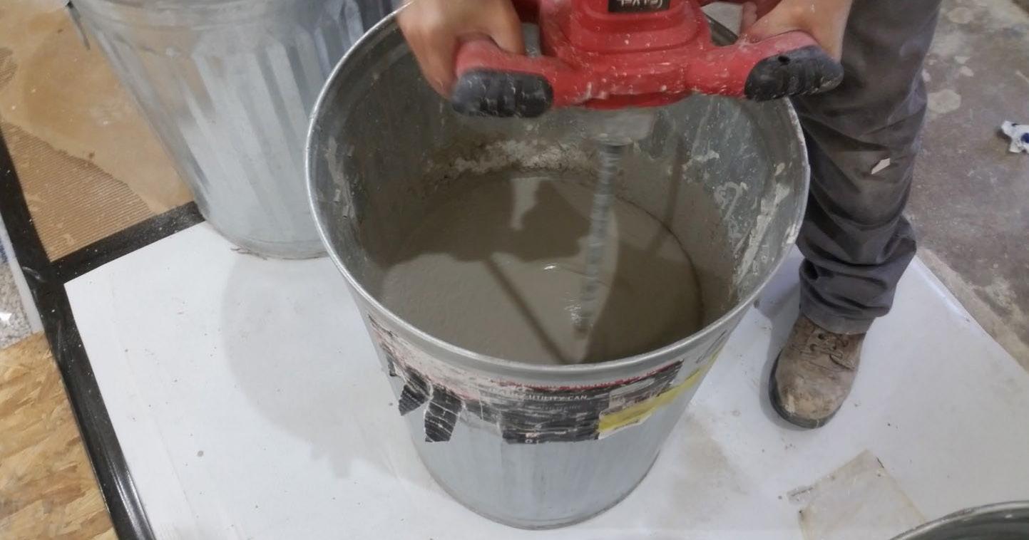
Mix Ratio: 2.5 gal. water / 40 lbs gypcrete / 75 lbs. all-purpose sand
Overall Weight: 469.47 kg (1035 lbs)
Mass/Unit Volume: 1780 kg/m3 (111 lbs/ ft3)
Installation: Poured over plywood subfloor. Gauge rake was used to level produt to 1” of thickness. Wet gypcrete mix was poured on (2024.07.01, approx. 3:40pm)
Material: Sustain 1195 Sheet and Tile adhesive
Manufacturer: Forbo
Dimensions: Approx. 2438 mm (96 in.) by 4267 mm (168 in.) as installed
Overall Weight: 2.95 kg (6.5 lbs)
Mass / Unit Area: 0.28 kg/m2 (0.06 lbs/ ft2)
Installation: Troweled directly to plywood with a 1/16x1/16x1/16 square notch trowel
Once troweled, adhesive was left “open” for 15 min to allow it to “tack” before flooring was installed.
Material: Marmoleum Decibel
Manufacturer: Forbo
Dimensions: 2 pieces @ 2007 mm (79 in.) by 2464 mm (97 in.)
Thickness: 6 mm (0.25 in.)
Overall Weight: 35.38 kg (78 lbs)
Mass / Unit Volume: 529 kg/m3 (33.0 lbs/ft3)
Installation: Two (2) 79” segments perpendicular to Plywood 10” strip to complete. Joints staggered from parallel plywood joints by + 6”. Rolled with 100lb roller in each direction.
SPECIMEN MEASUREMENTS
Dimensions: 2.44 m (96.0 in) wide by 3.86 m (152.0 in) high
Thickness: 0.33 m (12.875 in)
Weight: 1698.93 kg (3745.5 lbs)
Overall Area: 9.414 m2 (101.33 ft2)
Mass/Unit Area: 163.28 kg/m2 (33.44 lbs/ft2)
Opening Size: 4.27 m (14.0 ft) x 6.10 m (20.0 ft)
Filler Wall: Yes
Aperture Size: 2.44 m (96.0 in) wide by 3.86 m (152.0 in) high
Transmission Area: 9.414 m2 (101.33 ft2)
Sealed: Entire periphery (both sides) with dense mastic
Source Room Volume: 130.9 m3
Temperature: 22.8°C ±0.0°C
Relative Humidity: 62.0% ± 0.0%
Receive Room
Volume: 81.44 m3
Temperature: 22.2°C ± 1.1°C
Relative Humidity: 64.0% ± 2.0%
Requirements
Temperature: 22°C +/- 5°C, not more than 3°C change over all tests.
Relative Humidity: ≥ 30%, not more than +/- 3% change over all tests.
LAYER 1 - CROSS LAMINATED TIMBER (CLT)
Material: 5-Ply Cross-Laminated Timber
Dimensions: 2 panels @ 1219 mm (48 in.) by 4229 mm (166.5 in.)
Thickness: 171 mm (6.75 in.)
Overall Weight: 953.45 kg (2102 lbs)
Mass / Unit Volume: 539 kg/m3 (33.7 lbs/ft3)
Installation: CLT panels laid on 152 mm (6 in.) wide knee walls in test opening and butted to one another without sealant/adhesive. 3/4”x3” Rabbet on top side of one edge of each panel where they butt allowing a loose spline (below) to insert and join the two.
LAYER 2 - 3/4” CDX LOOSE SPLINE
Material: 3/4” x 6” plywood spline
Dimensions:
1 piece @ 151 mm (5.9375 in.) wide by 2438 mm (96 in.)
1 piece @ 151 mm (5.9375 in.) wide by 1791 mm (70.5 in.)
Thickness: 19 mm (0.75 in.)
Overall Weight: 6.46 kg (14.25 lbs)
Mass / Unit Length: 1.53 kg/m (1.03 lbs/ ft)
Installation: Set in Rabbets of both CLT’s and screwed in place.
Fasteners: WSV Bugle head sub-floor screws, length @ 76 mm (3 in.)
Fastener Spacing: 6” o.c. on a line 3” from each edge of the spline (Centered on the rabbet of the CLT)
LAYER 3 - PIANO B 40/40 (LOWER LAYER)
Manufacturer: Rothoblaas
Dimensions:
2 strips @ 40 mm (1.5625 in.) wide by 4267 mm (168 in.) long
8 strips @ 2362 mm (93 in.) wide by 40 mm (1.5625 in.) long
Thickness: 6.76 mm (0.266 in.)
Overall Weight: 4.59 kg (10.125 lbs)
Mass/Unit Volume: 624 kg/m3 (40.00 lbs/ft3)
Installation: Fastened to underside of 2” x 4” wood sleepers with staples
Fasteners: Arrow staples, length @ 13 mm (0.5 in.)
LAYER 4 - 2x4 SPF FRAMING SLEEPERS
Material: Nominal 2x4 framing lumber
Dimensions:
2 pieces @ 38 mm (1.5 in.) wide by 4255 mm (167.5 in. long
8 pieces @ 2369 mm (93.25 in.) wide by 38 mm (1.5 in.) long
Depth: 89 mm (3.5 in.)
Overall Weight: 49.33 kg (108.75 lbs)
Mass / Unit Length: 1.80 kg/m (1.21 lbs/ ft)
Installation: Sleepers laid over CLT, resting on lower layer Piano B 40/40. Longer sleepers parallel to CLT like a rim joist. Shorter sleepers set like floor joists between rim joists. Shorter sleepers spaced approx. 610 mm (24 in.) on center. Shorter sleepers fastened to longer sleepers with screws, 2 screws per connection point.
Fasteners: WSV Bugle head sub-floor screws, length @ 76 mm (3 in.)
LAYER 5 - PIANO B 40/40 (UPPER LAYER)
Manufacturer: Rothoblaas
Dimensions:
2 strips @ 40 mm (1.5625 in.) wide by 4267 mm (168 in.) long
8 strips @ 2362 mm (93 in.) wide by 40 mm (1.5625 in.) long
Thickness: 6.76 mm (0.266 in.)
Overall Weight: 4.59 kg (10.125 lbs)
Mass/Unit Volume: 624 kg/m3 (40.0 lbs/ft3)
Installation: Fastened to top of 2” x 4” wood sleepers with staples.
Fasteners: Arrow staples, length @ 13 mm (0.5 in.)
LAYER 6 - HEMPBOARD
Manufacturer: Hempitecture
Dimensions:
7 pieces @ 572 mm (22.5 in.) wide by 2369 mm (93.25 in.) long
Thickness: 76 mm (3 in.)
Overall Weight: 37.53 kg (82.75 lbs)
Mass/Unit Volume: 52 kg/m3 (3.25 lbs/ ft3)
Installation: Friction fit between sleepers on top of CLT.
Material: T&G Plywood
Dimensions:
1 piece @ 1219 mm (48 in.) wide by 1829 mm (72 in.)
1 piece @ 1219 mm (48 in.) wide by 2438 mm (96 in.)
1 piece @ 1219 mm (48 in.) wide by 1822 mm (71.75 in.)
1 piece @ 1219 mm (48 in.) wide by 2432 mm (95.75 in.)
Thickness: 29 mm (1.125 in.)
Overall Weight: 173.5 kg (382.5 lbs)
Mass / Unit Volume: 584 kg/m3 (36.5 lbs/ft3)
Installation: Placed over upper layer Piano B 40/40 over sleepers. Fastened to sleepers through Piano B 40/40 with screws. Plywood piece joints staggered. Fasteners: WSV Bugle head sub-floor screws, length @ 76 mm (3 in.)
Fastener Spacing: 610 mm (24 in.) on center
Manufacturer: Maxxon
Dimensions:
2438 mm (96 in.) by 4267 mm (168 in.) as installed
Thickness: Approx. 25 mm (1 in.)
Mix Ratio: 2.5 gal. water / 40 lbs gypcrete / 75 lbs. all-purpose sand
Overall Weight: 469.47 kg (1035 lbs)
Mass/Unit Volume: 1780 kg/m3 (111 lbs/ ft3)
Installation: Poured over plywood subfloor. Gauge rake was used to level produt to 1” of thickness. Wet gypcrete mix was poured on (2024.07.01, approx. 3:40pm)
*All images in Figures 9-13 credit Riverbank Acoustical Laboratories
SPECIMEN MEASUREMENTS
Dimensions: 2.44 m (96.0 in) wide by 3.86 m (152.0 in) high
Thickness: 0.33 m (13.0 in)
Weight: 2811.14 kg (6197.5 lbs)
Overall Area: 9.414 m2 (101.33 ft2)
Mass/Unit Area: 270.17 kg/m2 (55.33 lbs/ft2)
Opening Size: 4.27 m (14.0 ft) x 6.10 m (20.0 ft)
Filler Wall: Yes
Aperture Size: 2.44 m (96.0 in) wide by 3.86 m (152.0 in) high
Transmission Area: 9.414 m2 (101.33 ft2)
Sealed: Entire periphery (both sides) with dense mastic
Source Room Volume: 130.9 m3
Temperature: 23.1°C ±0.6°C
Relative Humidity: 67.0% ± 2.0%
Receive Room Volume: 81.44 m3
Temperature: 22.5°C ± 0.6°C
Relative Humidity: 67.0% ± 2.0%
Requirements
Temperature: 22°C +/- 5°C, not more than 3°C change over all tests.
Relative Humidity: ≥ 30%, not more than +/- 3% change over all tests.
LAYER 1 - CROSS LAMINATED TIMBER (CLT)
Material: 5-Ply Cross-Laminated Timber
Dimensions: 2 panels @ 1219 mm (48 in.) by 4229 mm (166.5 in.)
Thickness: 171 mm (6.75 in.)
Overall Weight: 953.45 kg (2102 lbs)
Mass / Unit Volume: 539 kg/m3 (33.7 lbs/ft3)
Installation: CLT panels laid on 152 mm (6 in.) wide knee walls in test opening and butted to one another without sealant/adhesive. 3/4”x3” Rabbet on top side of one edge of each panel where they butt allowing a loose spline (below) to insert and join the two.
LAYER 2 - 3/4” CDX LOOSE SPLINE
Material: 3/4” x 6” plywood spline
Dimensions:
1 piece @ 151 mm (5.9375 in.) wide by 2438 mm (96 in.)
1 piece @ 151 mm (5.9375 in.) wide by 1791 mm (70.5 in.)
Thickness: 19 mm (0.75 in.)
Overall Weight: 6.46 kg (14.25 lbs)
Mass / Unit Length: 1.53 kg/m (1.03 lbs/ ft)
Installation: Set in Rabbets of both CLT’s and screwed in place.
Fasteners: WSV Bugle head sub-floor screws, length @ 76 mm (3 in.)
Fastener Spacing: 6” o.c. on a line 3” from each edge of the spline (Centered on the rabbet of the CLT)
LAYER 3 - HEMPBOARD
Manufacturer: Hempitecture
Dimensions:
3 pieces @ 1216 mm (47.875 in.) wide by 2448 mm (96.375 in.) long
1 piece @ 613 mm (24.125 in.) wide by 2448 mm (96.375 in.) long
Thickness: 51 mm (2 in.)
Overall Weight: 69.51 kg (153.25 lbs)
Mass/Unit Volume: 131 kg/m3 (8.19 lbs/ ft3)
Installation: Loosely laid directly on top of CLT, perpendicular to CLT.
Material: CA-16 3/8” chip crushed limestone
Dimensions: 2438 mm (96 in.) wide by 4267 mm (168 in.) long, as installed Depth: 76 mm (3 in.)
Overall Weight: 1224.02 kg (2698.5 lbs)
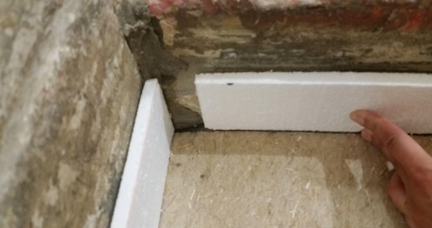
Installation: Loose laid on top of hemp fiberboard. 1/2” polystyrene used as an isolation around the perimeter.
Material: Membrain Vapor Barrier
Manufacturer: Saint Gobain
Dimensions: Approx. 2438 mm (96in.) by 4267 mm (168 in.) as installed
Overall Weight: 0.79 kg (1.75 lbs)
Mass / Unit Area: 0.08 kg/m2 (0.02 lbs/ ft2)
Installation: Loose laid over crushed limestone.
Manufacturer: Maxxon
Dimensions: 2438 mm (96 in.) by 4267 mm (168 in.) as installed
Thickness: Approx. 25 mm (1 in.)
Mix Ratio: 2.5 gal. water / 40 lbs gypcrete / 75 lbs. all-purpose sand
Overall Weight: 521.63 kg (1150 lbs)
Mass/Unit Volume: 1970 kg/m3 (123 lbs/ft3)
Installation: Poured over vapor barrier. A screed was used to spread the wet gypcrete mix. Wet gypcrete mix was poured on (2024.07.10, approx. 4:30pm)
Material: Sustain 1195 Sheet and Tile adhesive
Manufacturer: Forbo
Dimensions: Approx. 2438 mm (96 in.) by 4267 mm (168 in.) as installed
Overall Weight: 3.06 kg (6.75 lbs)
Mass / Unit Area: 0.29 kg/m2 (0.06 lbs/ ft2)
Installation: Troweled directly to plywood with a 1/16x1/16x1/16 square notch trowel
Once troweled, adhesive was left “open” for 15 min to allow it to “tack” before flooring was installed.
Material: Marmoleum Decibel
Manufacturer: Forbo
Dimensions: 2 pieces @ 2007 mm (79 in.) by 2464 mm (97 in.)
Thickness: 6 mm (0.25 in.)
Overall Weight: 32.21 kg (71 lbs)
Mass / Unit Volume: 482 kg/m3 (30.1 lbs/ft3)
Installation: Two (2) 79” segments perpendicular to Plywood 10” strip to complete. Rolled with 100lb roller in each direction.
*Level corrected due to background noise per E492 SEC 10.2.2 **Level corrected due to background noise per E492 SEC 10.2.3
SPECIMEN MEASUREMENTS
Dimensions: 2.44 m (96.0 in) wide by 3.86 m (152.0 in) high
Thickness: 0.32 m (12.75 in)
Weight: 2775.87 kg (6119.75 lbs)
Overall Area: 9.414 m2 (101.33 ft2)
Mass/Unit Area: 266.78 kg/m2 (54.64 lbs/ft2)
Opening Size: 4.27 m (14.0 ft) x 6.10 m (20.0 ft)
Filler Wall: Yes
Aperture Size: 2.44 m (96.0 in) wide by 3.86 m (152.0 in) high
Transmission Area: 9.414 m2 (101.33 ft2)
Sealed: Entire periphery (both sides) with dense mastic
Source Room Volume: 130.9 m3
Temperature: 23.3°C ±0.0°C
Relative Humidity: 67.5% ± 1.0%
Receive Room Volume: 81.44 m3
Temperature: 22.2°C ± 0.0°C
Relative Humidity: 67.0% ± 0.0%
Requirements
Temperature: 22°C +/- 5°C, not more than 3°C change over all tests.
Relative Humidity: ≥ 30%, not more than +/- 3% change over all tests.
LAYER 1 - CROSS LAMINATED TIMBER (CLT)
Material: 5-Ply Cross-Laminated Timber
Dimensions: 2 panels @ 1219 mm (48 in.) by 4229 mm (166.5 in.)
Thickness: 171 mm (6.75 in.)
Overall Weight: 953.45 kg (2102 lbs)
Mass / Unit Volume: 539 kg/m3 (33.7 lbs/ft3)
Installation: CLT panels laid on 152 mm (6 in.) wide knee walls in test opening and butted to one another without sealant/adhesive. 3/4”x3” Rabbet on top side of one edge of each panel where they butt allowing a loose spline (below) to insert and join the two.
2 - 3/4” CDX LOOSE SPLINE
Material: 3/4” x 6” plywood spline
Dimensions:
1 piece @ 151 mm (5.9375 in.) wide by 2438 mm (96 in.)
1 piece @ 151 mm (5.9375 in.) wide by 1791 mm (70.5 in.)
Thickness: 19 mm (0.75 in.)
Overall Weight: 6.46 kg (14.25 lbs)
Mass / Unit Length: 1.53 kg/m (1.03 lbs/ ft)
Installation: Set in Rabbets of both CLT’s and screwed in place.
Fasteners: WSV Bugle head sub-floor screws, length @ 76 mm (3 in.)
Fastener Spacing: 6” o.c. on a line 3” from each edge of the spline (Centered on the rabbet of the CLT)
Manufacturer: Hempitecture
Dimensions:
3 pieces @ 1216 mm (47.875 in.) wide by 2448 mm (96.375 in.) long
1 piece @ 613 mm (24.125 in.) wide by 2448 mm (96.375 in.) long
Thickness: 51 mm (2 in.)
Overall Weight: 69.51 kg (153.25 lbs)
Mass/Unit Volume: 131 kg/m3 (8.19 lbs/ ft3)
Installation: Loosely laid directly on top of CLT, perpendicular to CLT.
Material: CA-16 3/8” chip crushed limestone
Dimensions: 2438 mm (96 in.) wide by 4267 mm (168 in.) long, as installed Depth: 76 mm (3 in.)
Overall Weight: 1224.02 kg (2698.5 lbs)
Installation: Loose laid on top of hemp fiberboard. 1/2” polystyrene used as an isolation around the perimeter.
Material: Membrain Vapor Barrier
Manufacturer: Saint Gobain
Dimensions: Approx. 2438 mm (96in.) by 4267 mm (168 in.) as installed
Overall Weight: 0.79 kg (1.75 lbs)
Mass / Unit Area: 0.08 kg/m2 (0.02 lbs/ ft2)
Installation: Loose laid over crushed limestone.
Manufacturer: Maxxon
Dimensions:
2438 mm (96 in.) by 4267 mm (168 in.) as installed
Thickness: Approx. 25 mm (1 in.)
Mix Ratio: 2.5 gal. water / 40 lbs gypcrete / 75 lbs. all-purpose sand
Overall Weight: 521.63 kg (1150 lbs)
Mass/Unit Volume: 1970 kg/m3 (123 lbs/ft3)
Installation: Poured over vapor barrier. A screed was used to spread the wet gypcrete mix. Wet gypcrete mix was poured on (2024.07.10, approx. 4:30pm)
FREQ. = FREQUENCY, HERTZ
Ln = 95% UNCERTAINTY LIMIT FOR Ln, dB
= DEVIATION FROM SHIFTED IIC COUNTOUR, dB IIC = IMPACT INSULATION CLASS
*Level corrected due to background noise per E492 SEC 10.2.2 **Level corrected due to background noise per E492 SEC 10.2.3
All nine tested assemblies exceeded an STC rating of 50, the IBC minimum acoustic separation requirement for labtested assemblies, all reaching at least a rating of 58, with the highest performing reaching a rating of 60. Five of the nine tested floor/ceiling assemblies were able to achieve a performance level of 50 for both STC and IIC ratings. Three of those five assemblies were able to exceed a 50 rating for both indicators of acoustic performance (F03, F06, and F07). Floor assembly F03 had the best overall performance, with the highest STC and IIC ratings of all assemblies at 60 and 55, respectively.
Detailed acoustic performance results for both IIC and STC for each assembly can be found in Section 03, above, including respective spectral data.
The test results in this report demonstrate that it is possible to develop a lower carbon floorceiling assembly that, through the increased use of bio-based materials and elimination of concrete, is able to not only achieve acoustic code requirements for the separation of units in multifamily housing, but also surpass code required performance minimums for sound transmission and impact isolation class.
This section includes the complete certified ASTM testing reports for transmission loss (TL) and impact sound transmission (IIC) by Riverbank Acoustical Laboratories™.
627 RIVERBANK DRIVE
GENEVA, IL 60134
630-232-0104
www.riverbankacoustics.com
SPONSOR: University of Oregon Impact Sound Transmission Portland, OR RAL™-IN24-015
CONDUCTED: 2024-06-21 Page 1 of 19
ON: Marmoleum Decibel adhered with Sustain 1195, 1-1/8” T&G plywood subfloor screwed 24” OC with #9x3”, cavity filled with: 3.75” of 3/8” limestone chip, 2x4 sleepers 24”OC with Rothoblaas Piano B acoustic strips stapled top/bottom, Vaagen Timbers 5-ply CLT 6.875” with plywood spline 3/4”x6” at the joint secured with #9x3” screws at 6” OC
Riverbank Acoustical Laboratories™ is accredited by the U.S. Department of Commerce, National Institute of Standards and Technology (NIST) under the National Voluntary Laboratory Accreditation Program (NVLAP) as an ISO 17025:2017 Laboratory (NVLAP Lab Code: 100227-0) and for this test procedure. The test reported in this document conformed explicitly with ASTM E492-22: "Standard Test Method for Laboratory Measurement of Impact Sound Transmission Through Floor-Ceiling Assemblies Using the Tapping Machine." The single-number rating of the specimen was calculated according to ASTM E989-21: "Standard Classification for Determination of Single-Number Metrics for Impact Noise." A description of the measurement procedure and room specifications are available upon request. The results presented in this report apply to the individual test specimen as described and assembled.
The test specimen was designated by the sponsor as Marmoleum Decibel adhered with Sustain 1195, 11/8” T&G plywood subfloor screwed 24” OC with #9x3”, cavity filled with: 3.75” of 3/8” limestone chip, 2x4 sleepers 24”OC with Rothoblaas Piano B acoustic strips stapled top/bottom, Vaagen Timbers 5-ply CLT 6.875” with plywood spline 3/4”x6” at the joint secured with #9x3” screws at 6” OC. The following nominal product information was provided by the sponsor prior to testing. The accuracy of such sponsor-provided information can affect the validity of the test results.
Product Under Test
Provided Description: Marmoleum Decibel adhered with Sustain 1195, 1-1/8” T&G plywood subfloor screwed 24” OC with #9x3", cavity filled with: 3.75” of 3/8" limestone chip, 2x4 sleepers 24”OC with Rothoblaas Piano B acoustic strips stapled top/bottom, Vaagen Timbers 5-ply CLT 6.875” with plywood spline 3/4”x6” at the joint secured with #9x3” screws at 6” OC
Manufacturer: University of Oregon

ACOUSTICAL LABORATORIES IS
(LAB
University of Oregon
2024-06-21
Page 2 of 19
The building contractor (Seth Priser) and RAL staff compiled a detailed construction specification as follows:
Cross-Laminated Timber (CLT)
Materials: 5-Ply Cross-Laminated Timber
Dimensions: 2 panels @ 1219 mm (48 in.) by 4229 mm (166.5 in.)
Thickness: 171 mm (6.75 in.)
Overall Weight: 953.45 kg (2102 lbs)
Mass Per Unit Volume: 539 kg/m3 (33.7 lbs/ft3)
Installation: CLT panels laid on 152 mm (6 in.) wide knee walls in test opening and butted to one another without sealant/adhesive.
3/4”x3” Rabbet on top side of one edge of each panel where they butt allowing a loose spline (below) to insert and join the two
Materials: 3/4” x 6” plywood spline
Dimensions: 1 piece @ 151 mm (5.9375 in.) wide by 2438 mm (96 in.) 1 piece @ 151 mm (5.9375 in.) wide by 1791 mm (70.5 in.)
Thickness: 19 mm (0.75 in.)
Overall Weight: 6.46 kg (14.25 lbs)
Mass Per Unit Length: 1.53 kg/m (1.03 lbs/ft)
Installation: Set in Rabbets of both CLT’s and screwed in place.
Fasteners: WSV Bugle head sub-floor screws, length @ 76 mm (3 in.)
Fastener Spacing: 6” o.c. on a line 3” from each edge of the spline (Centered on the rabbet of the CLT)
Piano B 40/40 (Lower Layer)
Manufacturer: Rothoblaas
Dimensions: 2 strips @ 40 mm (1.5625 in.) wide by 4267 mm (168 in.) long 8 strips @ 2362 mm (93 in.) wide by 40 mm (1.5625 in.) long
Thickness: 6.76 mm (0.266 in.)
Overall Weight: 4.59 kg (10.125 lbs)
Mass Per Unit Volume: 624 kg/m3 (40.0 lbs/ft3)
Installation: Fastened to underside of 2” x 4” wood sleepers with staples
Fasteners: Arrow staples, length @ 13 mm (0.5 in.)
University of Oregon
2024-06-21
SPECIMEN MEASUREMENTS & TEST CONDITIONS (continued)
2” by 4” SPF Framing Sleepers
Materials: Nominal 2”x 4” framing lumber
Page 3 of 19
Dimensions: 2 pieces @ 38 mm (1.5 in.) wide by 4255 mm (167.5 in.) long
8 pieces @ 2369 mm (93.25 in.) wide by 38 mm (1.5 in.) long
Depth: 89 mm (3.5 in.)
Overall Weight: 49.33 kg (108.75 lbs)
Mass Per Unit Length: 1.80 kg/m (1.21 lbs/ft)
Installation: Sleepers laid over CLT, resting on lower layer Piano B 40/40
Longer sleepers parallel to CLT like a rim joist
Shorter sleepers set like floor joists between rim joists
Shorter sleepers spaced approx. 610 mm (24 in.) on center
Shorter sleepers fastened to longer sleepers with screws, 2 screws per connection point
Fasteners: WSV Bugle head sub-floor screws, length @ 76 mm (3 in.)
Piano B 40/40 (Upper Layer)
Manufacturer: Rothoblaas
Dimensions: 2 strips @ 40 mm (1.5625 in.) wide by 4267 mm (168 in.) long
8 strips @ 2362 mm (93 in.) wide by 40 mm (1.5625 in.) long
Thickness: 6.76 mm (0.266 in.)
Overall Weight: 4.59 kg (10.125 lbs)
Mass Per Unit Volume: 624 kg/m3 (40.0 lbs/ft3)
Installation: Fastened to top of 2” x 4” wood sleepers with staples
Fasteners: Arrow staples, length @ 13 mm (0.5 in.)
Crushed Limestone
Materials: CA-16 3/8” chip crushed limestone
Dimensions: 2438 mm (96 in.) wide by 4267 mm (168 in.) long, as installed
Depth: 95 mm (3.75 in.)
Overall Weight: 1261.89 kg (2782 lbs)
Installation: Filled stone in between sleepers and used a screed to level to the top of the sleepers.
University of Oregon
2024-06-21
SPECIMEN MEASUREMENTS & TEST CONDITIONS (continued)
Plywood Subfloor
Materials: T&G Plywood
Dimensions: 1 piece @ 1219 mm (48 in.) wide by 1829 mm (72 in.)
1 piece @ 1219 mm (48 in.) wide by 2438 mm (96 in.)
1 piece @ 1219 mm (48 in.) wide by 1813 mm (71.375 in.)
1 piece @ 1219 mm (48 in.) wide by 2426 mm (95.5 in.)
Thickness: 29 mm (1.125 in.)
Overall Weight: 176.33 kg (388.75 lbs)
Mass Per Unit Volume: 595 kg/m3 (37.1 lbs/ft3)
Installation: Placed over upper layer Piano B 40/40 over sleepers
Fastened to sleepers through Piano B 40/40 with screws
Plywood piece joints staggered
Fasteners: WSV Bugle head sub-floor screws, length @ 76 mm (3 in.)
Fastener Spacing: 610 mm (24 in.) on center
Adhesive
Materials: Sustain 1195 Sheet and Tile adhesive
Manufacturer: Forbo
Dimensions: Approx. 2438 mm (96 in.) by 4267 mm (168 in.) as installed
Overall Weight: 4.54 kg (10 lbs)
Mass Per Unit Area: 0.44 kg/m2 (0.09 lbs/ft2)
Flooring
Page 4 of 19
Installation: Troweled directly to plywood with a 1/16x1/16x1/16 square notch trowel
Once troweled, adhesive was left “open” for 7-10 min to allow it to “tack” before flooring was installed.
Materials: Marmoleum Decibel
Manufacturer: Forbo
Dimensions: 2 pieces @ 2007 mm (79 in.) by 2464 mm (97 in.)
1 piece @ 257 mm (10.125 in.) by 2438 mm (96 in.)
Thickness: 6 mm (0.25 in.)
Overall Weight: 32.77 kg (72.25 lbs)
Mass Per Unit Volume: 491 kg/m3 (30.6 lbs/ft3)
Installation: Two (2) 79” segments perpendicular to Plywood 10” strip to complete Joints staggered from parallel plywood joints by + 6” Rolled with 100lb roller in each direction
University of Oregon RAL™-IN24-015 2024-06-21 Page 5 of 19
SPECIMEN MEASUREMENTS & TEST CONDITIONS (continued)
Overall Specimen Measurements
Dimensions: 2.44 m (96.0 in) wide by 3.86 m (152.0 in) long
Thickness: 0.31 m (12.125 in)
Weight: 2493.96 kg (5498.25 lbs)
Overall Area: 9.414 m² (101.33 ft²)
Mass per Unit Area: 239.69 kg/m² (49.09 lbs/ft²)
Test Aperture
Opening Size: 4.27 m (14.0 ft.) by 6.10 m (20 ft.)
Filler Wall: Yes
Aperture Size: 2.44 m (96.0 in) wide by 3.86 m (152.0 in) long
Transmission Area: 9.414 m² (101.33 ft²)
Sealed: Entire periphery (both sides) with dense mastic
Test Environment
Source Room
Volume: 131.12 m³
Temperature: 22.8 °C ± 0.0 °C
Relative Humidity: 59.0 % ± 0.0 %
Receive Room
Volume: 81.44 m³
Temperature: 21.1 °C ± 0.0 °C
Relative Humidity: 61.0 % ± 0.0 %
Requirements
Temperature: 22º C +/- 5° C, not more than 3° C change over all tests.
Relative Humidity: ≥ 30% RH; not more than +/- 3% change over all tests.
University of Oregon
2024-06-21
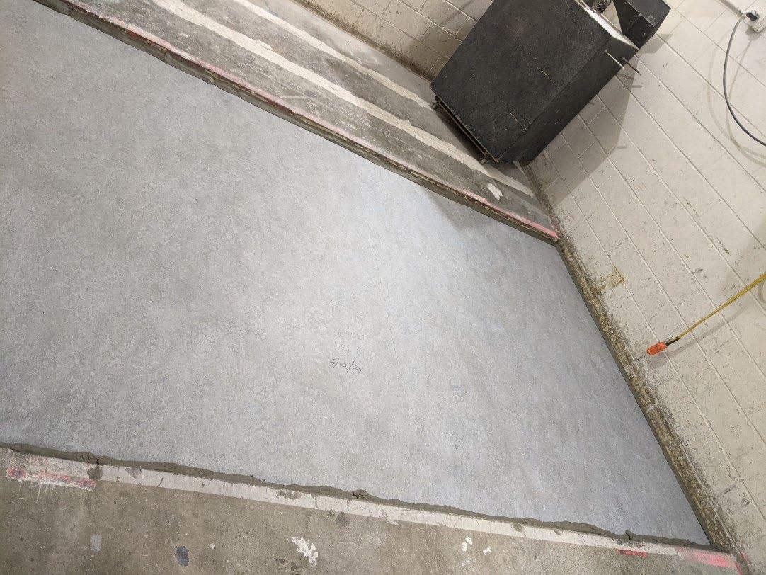
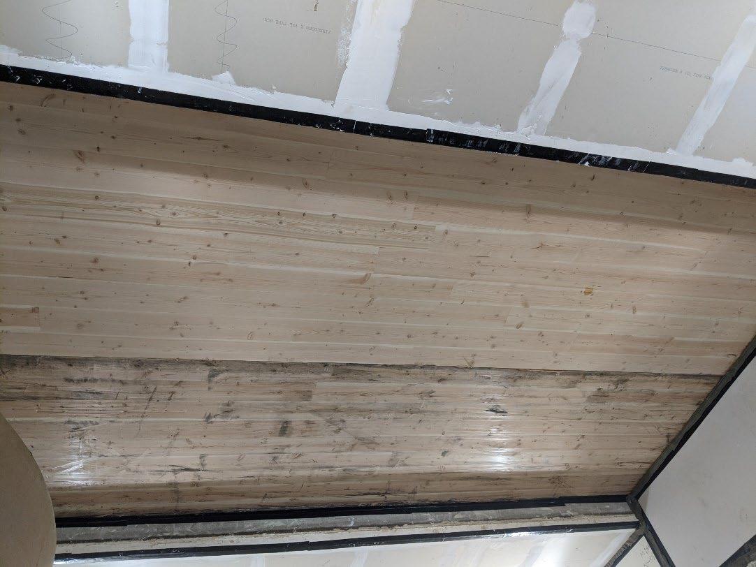
Page 6 of 19
University of Oregon
2024-06-21
Page 7 of 19
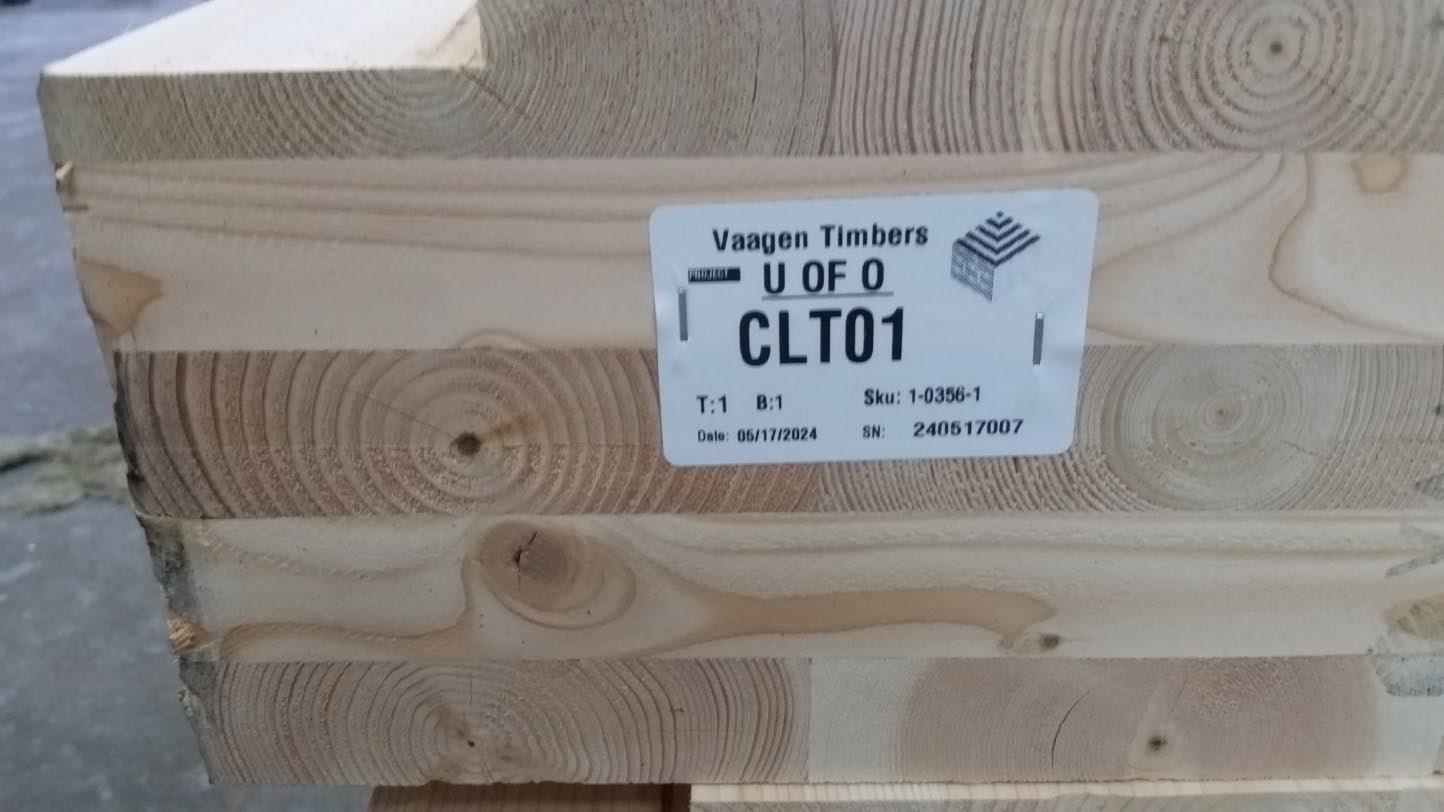
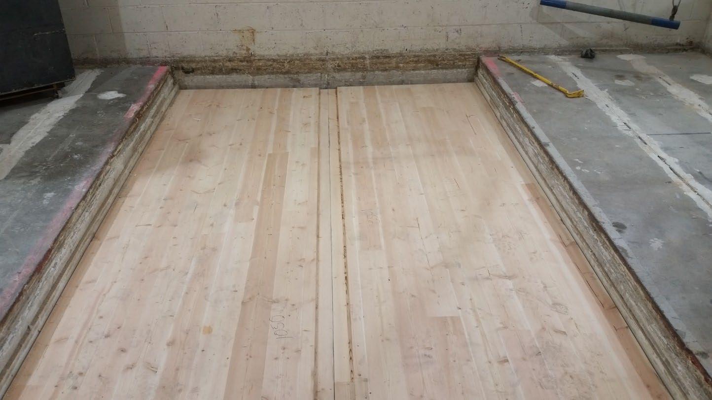
University of Oregon
2024-06-21 Page 8 of 19
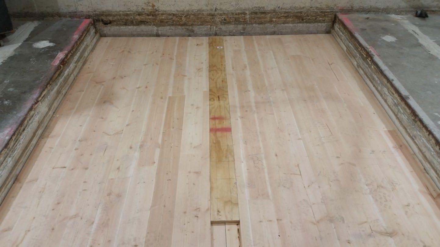
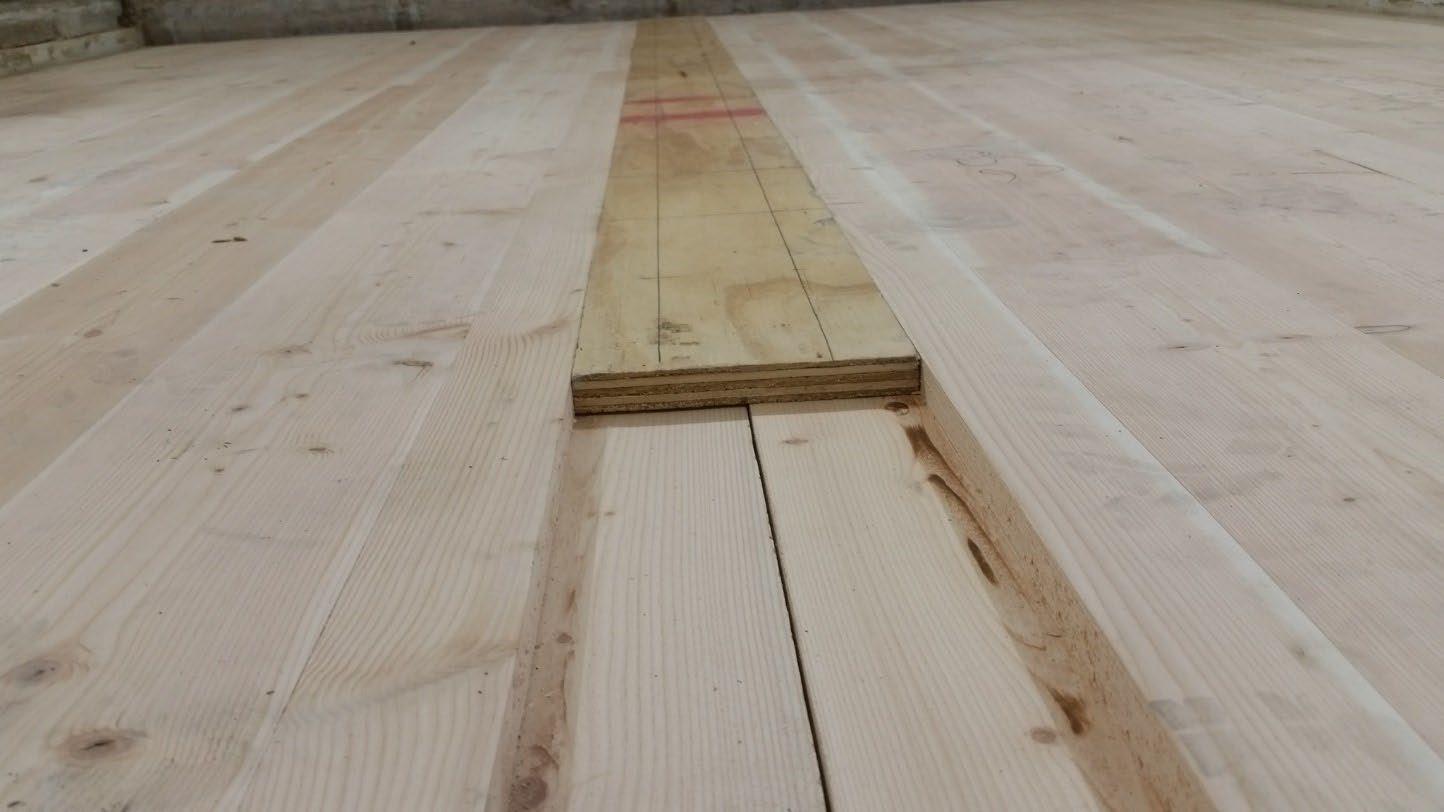
University of Oregon
2024-06-21 Page 9 of 19
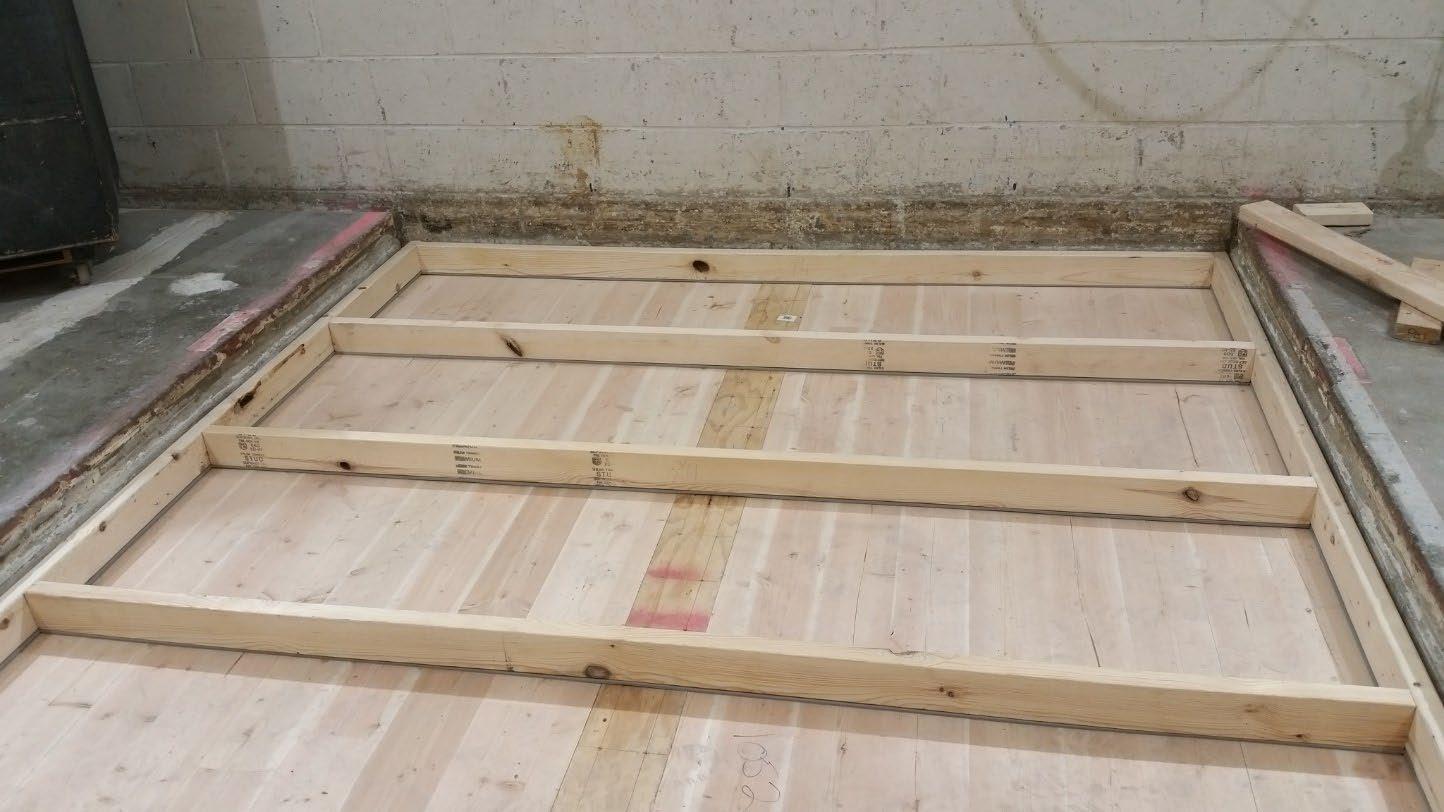
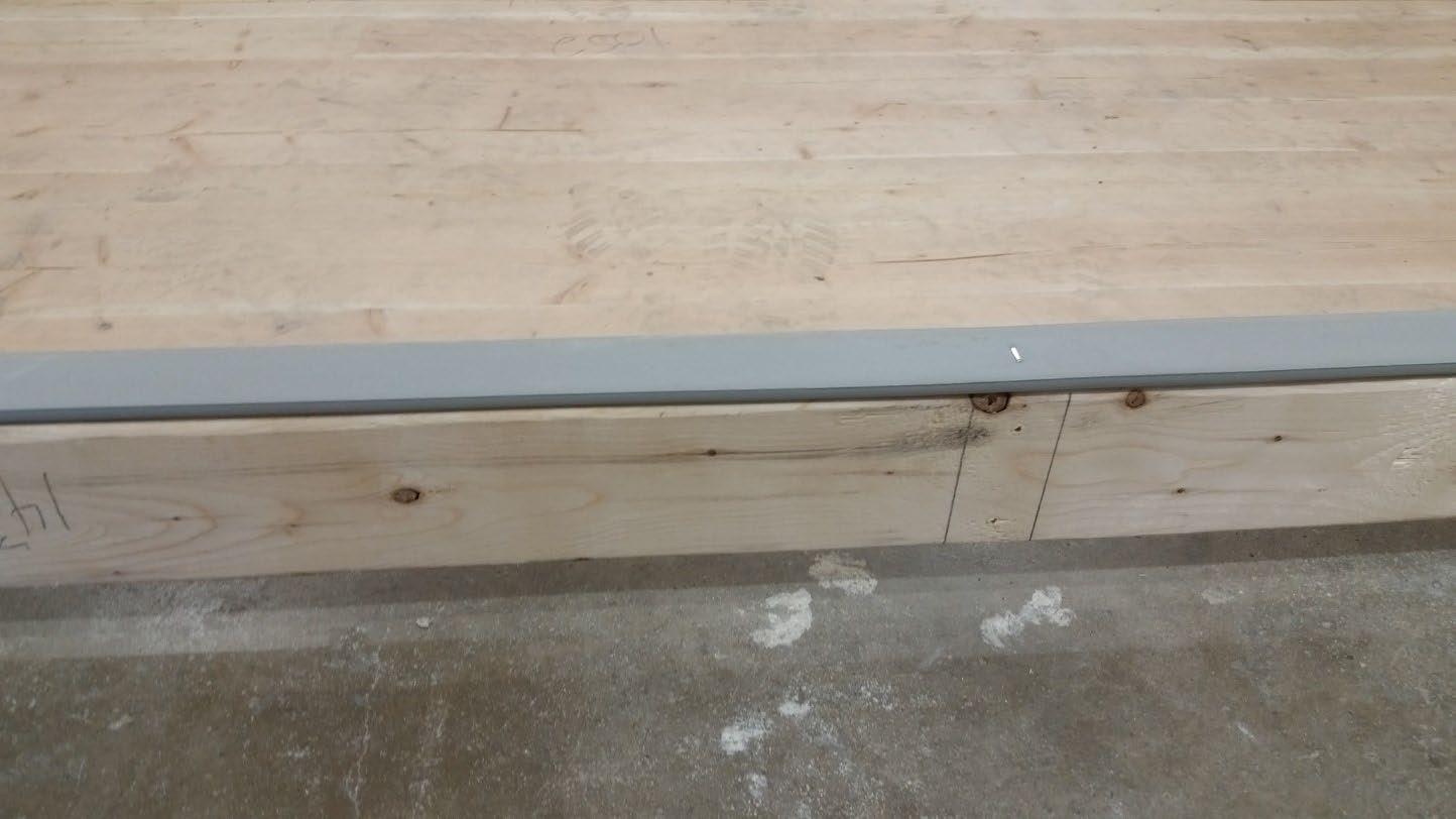
University of Oregon
2024-06-21 Page 10 of 19
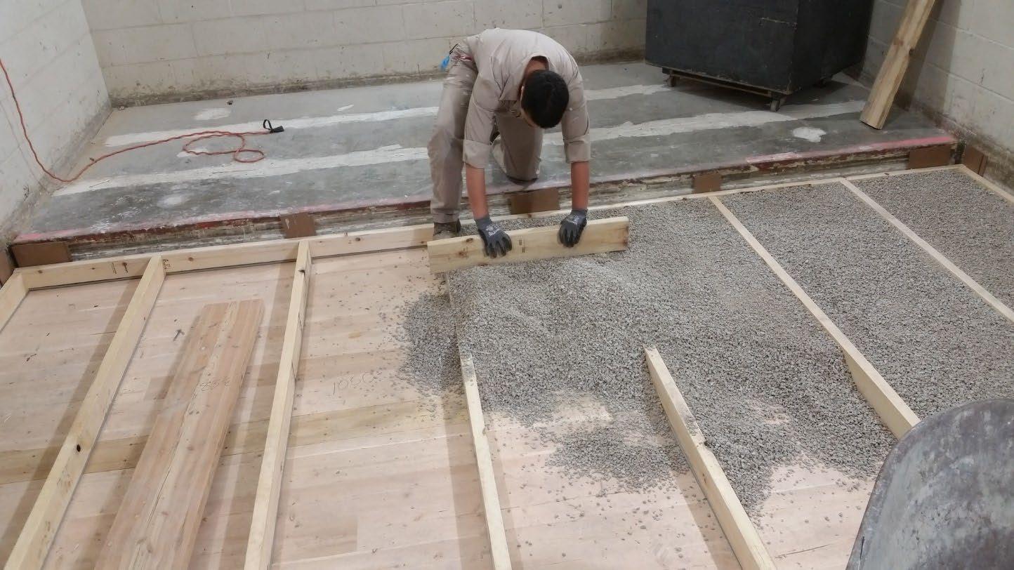
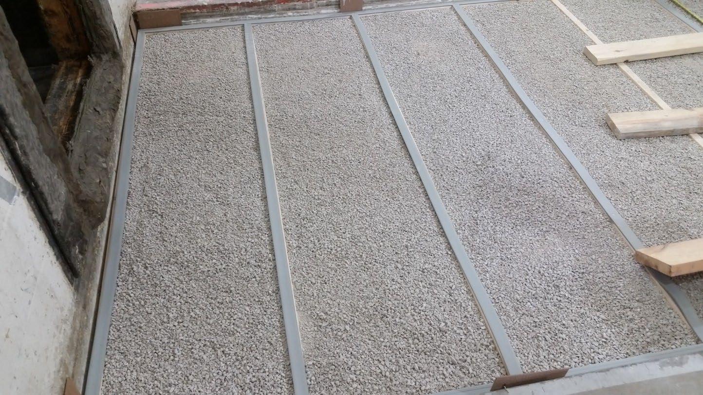
University of Oregon
2024-06-21 Page 11 of 19
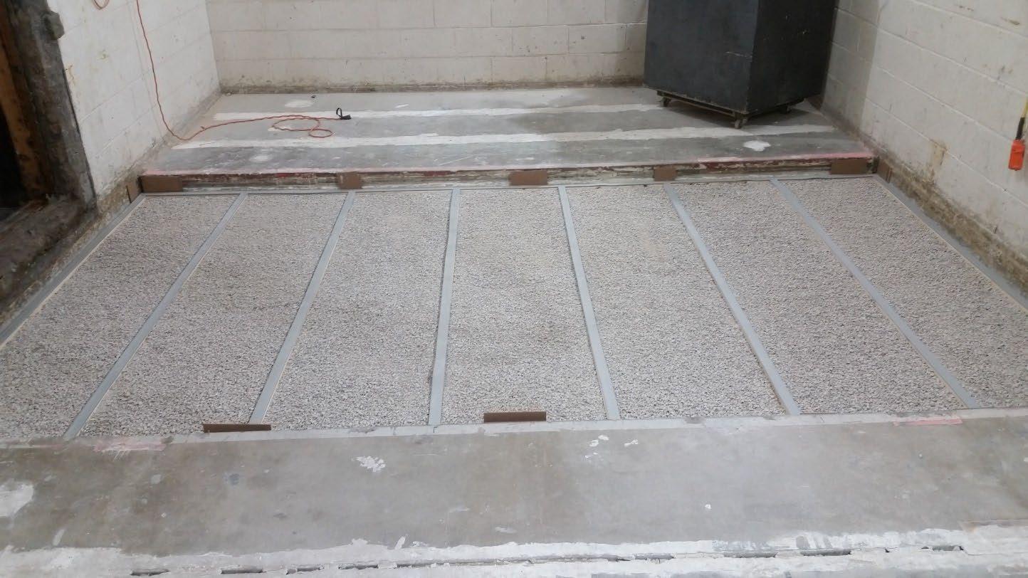

University of Oregon
2024-06-21 Page 12 of 19
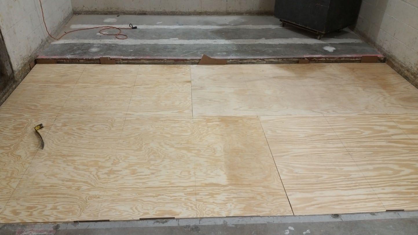
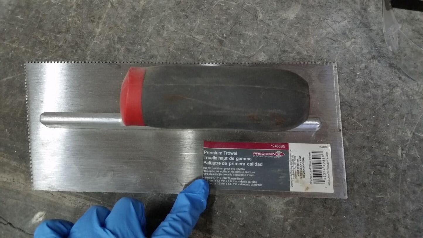
University of Oregon
2024-06-21 Page 13 of 19
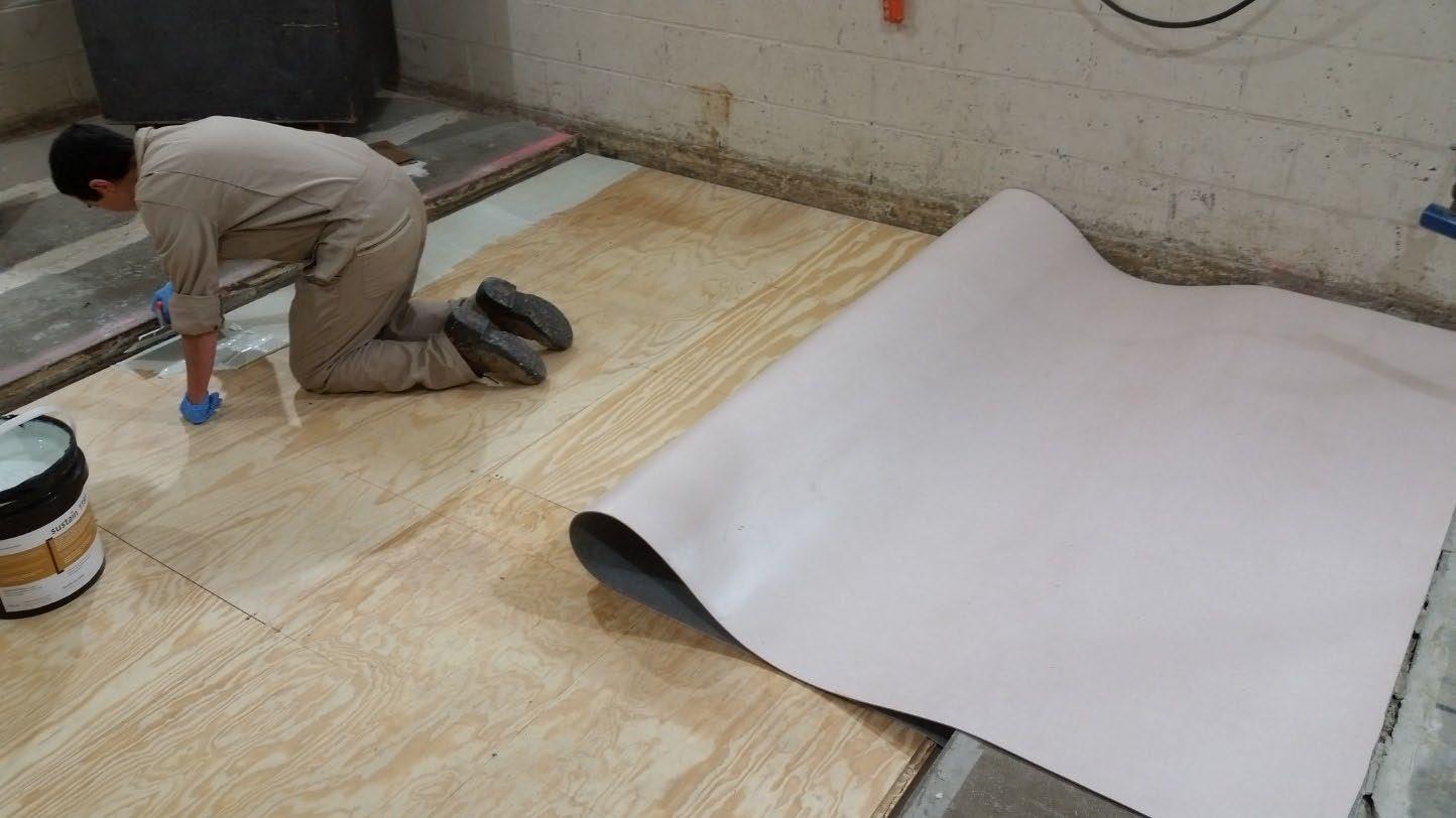
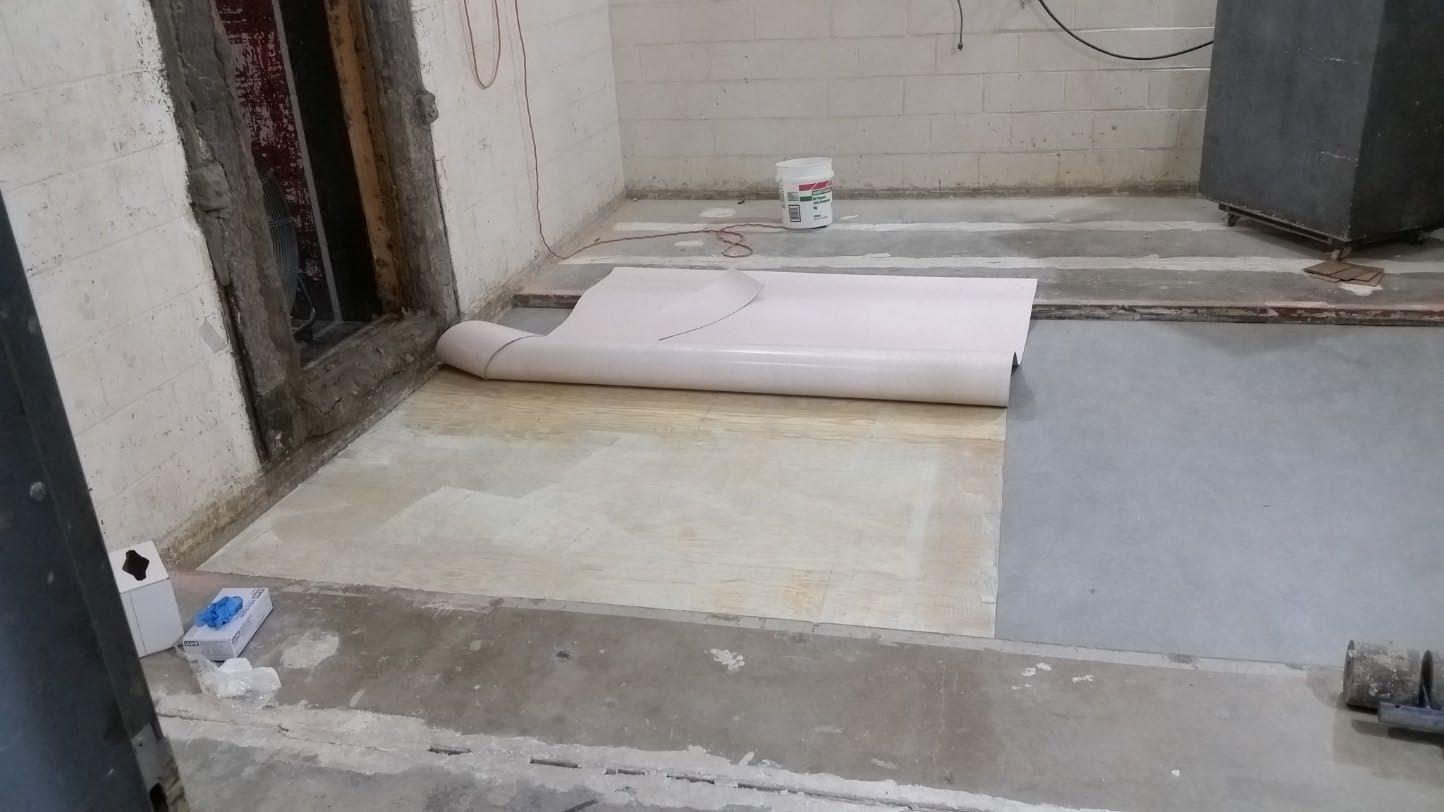
University of Oregon
2024-06-21 Page 14 of 19
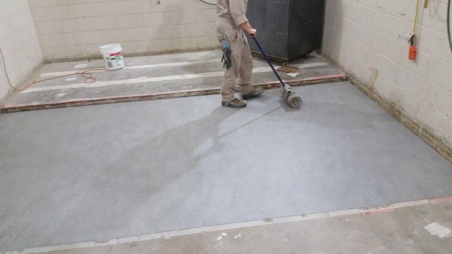
University of Oregon
2024-06-21 Page 15 of 19
The averaged sound pressure levels, normalized to a receive room reference absorption of 10 m2, are tabulated at the sixteen frequency bands specified in ASTM E492-22 Section 9.5. A graphic presentation of the data and additional information appear on the following pages. The 95% confidence limit for the sound pressure level in the receive room is below the limits specified in ASTM E492-22 Section A1.4.
IIC=55
ABBREVIATION INDEX
FREQ. = 1/3 OCTAVE BAND CENTER FREQUENCY, Hz
Ln = NORMALIZED SOUND PRESSURE LEVEL, dB
ΔLn = 95% UNCERTAINTY LIMIT FOR Ln, dB
DEV. = DEVIATION FROM SHIFTED IIC CONTOUR, dB (SUM OF DEV = 27 ) IIC = IMPACT INSULATION CLASS

Keith Kimberling Senior Experimentalist Test Engineer

Tested by______________________________ Report by__________________________

Approved by_______________________
Laboratory Manager
627 RIVERBANK DRIVE GENEVA, IL 60134 630-232-0104
University of Oregon
2024-06-21
Page 16 of 19
Marmoleum Decibel adhered with Sustain 1195, 1-1/8” T&G plywood subfloor screwed 24” OC with #9x3”, cavity filled with: 3.75” of 3/8” limestone chip, 2x4 sleepers 24”OC with Rothoblaas Piano B acoustic strips stapled top/bottom, Vaagen Timbers 5-ply CLT 6.875” with plywood spline 3/4”x6” at the joint secured with #9x3” screws at 6” OC
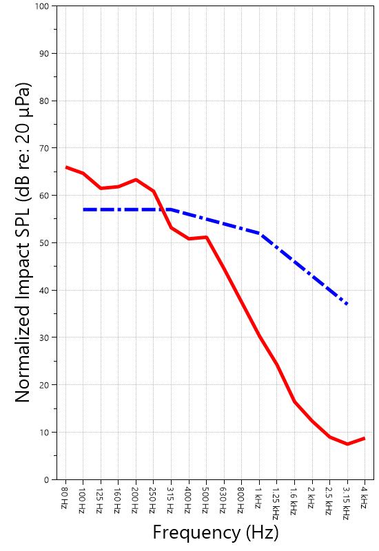
IMPACT SOUND PRESSURE LEVEL IMPACT INSULATION CLASS CONTOUR
627 RIVERBANK DRIVE GENEVA, IL 60134 630-232-0104
University of Oregon
2024-06-21 Page 17 of 19
Specimen: Marmoleum Decibel adhered with Sustain 1195, 1-1/8” T&G plywood subfloor screwed 24” OC with #9x3”, cavity filled with: 3.75” of 3/8” limestone chip, 2x4 sleepers 24”OC with Rothoblaas Piano B acoustic strips stapled top/bottom, Vaagen Timbers 5-ply CLT 6.875” with plywood spline 3/4”x6” at the joint secured with #9x3” screws at 6” OC (See Full Report)
The following non-accredited data were obtained in accordance with ASTM E492-22 but extend beyond the frequency range of 100 Hz to 3,150 Hz specified in Section 9.5. These unofficial results are representative of the RAL test environment only and intended for research & comparison purposes.
1/3 Octave Band
* Level corrected due to proximity to background noise per E492 Section 10.2.2
** Level corrected due to proximity to background noise per E492 Section 10.2.3, represents lower bound of specimen performance
627 RIVERBANK DRIVE GENEVA, IL 60134 630-232-0104
University of Oregon
2024-06-21
Page 18 of 19
Specimen: Marmoleum Decibel adhered with Sustain 1195, 1-1/8” T&G plywood subfloor screwed 24” OC with #9x3”, cavity filled with: 3.75” of 3/8” limestone chip, 2x4 sleepers 24”OC with Rothoblaas Piano B acoustic strips stapled top/bottom, Vaagen Timbers 5-ply CLT 6.875” with plywood spline 3/4”x6” at the joint secured with #9x3” screws at 6” OC (See Full Report)
ΔLn, the 95% confidence limit for the reported normalized sound pressure level, is calculated from the standard deviation of the set of sound pressure levels measured during this individual test. This metric is calculated in an effort to quantify the variability in measured levels due to the combined influences of varying sound pressure level in the receive room and changes in specimen response for different tapping machine locations.
Repeatability, expressed as a 95% confidence limit, is calculated from the standard deviation in normalized sound pressure level as obtained from a total of six consecutive tests conducted according to this test method by RAL from 2019-02-07 to 2019-02-12. The tests were performed on a specimen composed of 152.4 mm (6 in.) thick concrete slabs, which was left installed and unaltered between tests. This metric provides an estimate of the variation in results that might be observed if the test were repeated with no change to the installed specimen. Note that repeatability will vary with the construction type.
Specimen: Marmoleum Decibel adhered with Sustain 1195, 1-1/8” T&G plywood subfloor screwed 24” OC with #9x3”, cavity filled with: 3.75” of 3/8” limestone chip, 2x4 sleepers 24”OC with Rothoblaas Piano B acoustic strips stapled top/bottom, Vaagen Timbers 5-ply CLT 6.875” with plywood spline 3/4”x6” at the joint secured with #9x3” screws at 6” OC (See Full Report)
Current priorities in the architectural acoustics community involve the development of impact insulation metrics corresponding to impact sources of varying frequency content. Standard Classification ASTM E3222-20a provides a method for calculating the High-Frequency Impact Insulation Class (HIIC), using normalized impact sound pressure level (Ln) data at frequency bands from 400 Hz to 3150 Hz. Standard Classification ASTM E3207-21 provides a method for calculating the Low-Frequency Impact Insulation Class (LIIC) uses normalized impact sound pressure level (Ln) data at frequency bands from 50 Hz to 80 Hz.
Low-frequency impact noise correlates to the “thudding” of footfalls on lightweight structures, while high-frequency sound correlates to sources including the impacts of hard-heeled shoes, dragging furniture, dog toenails, and objects dropped on hard-surfaced flooring. When presented alongside the IIC rating, The LIIC and HIIC ratings can be used to predict how the nature of an impact source will affect the response of the floor-ceiling construction. A summary of impact insulation ratings, as calculated from the test results, is given below.
RIVERBANK DRIVE GENEVA, IL 60134 630-232-0104
University of Oregon RAL™-IN24-015 2024-06-21 Page 19 of 19
APPENDIX D: Instruments of Traceability
Specimen: Marmoleum Decibel adhered with Sustain 1195, 1-1/8” T&G plywood subfloor screwed 24” OC with #9x3”, cavity filled with: 3.75” of 3/8” limestone chip, 2x4 sleepers 24”OC with Rothoblaas Piano B acoustic strips stapled top/bottom, Vaagen Timbers 5-ply CLT 6.875” with plywood spline 3/4”x6” at the joint secured with #9x3” screws at 6” OC (See Full Report)
Description
System 2 Type 3160-A-042 3160106974 2023-08-11 2024-08-11
Bruel & Kjaer Mic And Preamp C Type 4943-B-001 2311439 2024-03-29 2025-03-29
Bruel & Kjaer Tapping Machine Type 3207 3151105 2023-12-14 2024-12-14
Bruel & Kjaer Pistonphone Type 4228 2781248 2023-07-12 2024-07-12
EXTECH Hygro 959 SD700 A.099959 2024-03-29 2025-03-29
EXTECH Hygro 639 SD700 A.103639 2023-12-01 2024-12-01
APPENDIX E: Revisions to Original Test Report
Specimen: Marmoleum Decibel adhered with Sustain 1195, 1-1/8” T&G plywood subfloor screwed 24” OC with #9x3”, cavity filled with: 3.75” of 3/8” limestone chip, 2x4 sleepers 24”OC with Rothoblaas Piano B acoustic strips stapled top/bottom, Vaagen Timbers 5-ply CLT 6.875” with plywood spline 3/4”x6” at the joint secured with #9x3” screws at 6” OC (See Full Report)
Date Revision
2024-07-31 Original report issued
2024-09-19 Page 16: Tapping machine added to instruments of traceability. -EPW
627 RIVERBANK DRIVE
GENEVA, IL 60134
630-232-0104
SPONSOR: University of Oregon Impact Sound Transmission Portland, OR RAL™-IN24-016
CONDUCTED: 2024-06-24 Page 1 of 16
ON: 1-1/8” T&G plywood subfloor screwed 24” OC with #9x3”, cavity filled with: 3” of 3/8” limestone chip and Hempitecture 3/4” hemp fiber board, 2x4 sleepers 24”OC with Rothoblaas Piano B acoustic strips stapled top/bottom, Vaagen Timbers 5-ply CLT 6.875”
Riverbank Acoustical Laboratories™ is accredited by the U.S. Department of Commerce, National Institute of Standards and Technology (NIST) under the National Voluntary Laboratory Accreditation Program (NVLAP) as an ISO 17025:2017 Laboratory (NVLAP Lab Code: 100227-0) and for this test procedure. The test reported in this document conformed explicitly with ASTM E492-22: "Standard Test Method for Laboratory Measurement of Impact Sound Transmission Through Floor-Ceiling Assemblies Using the Tapping Machine." The single-number rating of the specimen was calculated according to ASTM E989-21: "Standard Classification for Determination of Single-Number Metrics for Impact Noise." A description of the measurement procedure and room specifications are available upon request. The results presented in this report apply to the individual test specimen as described and assembled.
The test specimen was designated by the sponsor as 1-1/8” T&G plywood subfloor screwed 24” OC with #9x3”, cavity filled with: 3” of 3/8” limestone chip and Hempitecture 3/4” hemp fiber board, 2x4 sleepers 24”OC with Rothoblaas Piano B acoustic strips stapled top/bottom, Vaagen Timbers 5-ply CLT 6.875”. The following nominal product information was provided by the sponsor prior to testing. The accuracy of such sponsor-provided information can affect the validity of the test results.
Provided Description: 1-1/8” T&G plywood subfloor screwed 24” OC with #9x3", cavity filled with: 3” of 3/8" limestone chip and Hempitecture 3/4” hemp fiber board, 2x4 sleepers 24”OC with Rothoblaas Piano B acoustic strips stapled top/bottom, Vaagen Timbers 5-ply CLT 6.875"
Manufacturer: University of Oregon
SABINE
University of Oregon
2024-06-24
Page 2 of 16
The building contractor (Seth Priser) and RAL staff compiled a detailed construction specification as follows:
Cross-Laminated Timber (CLT)
Materials: 5-Ply Cross-Laminated Timber
Dimensions: 2 panels @ 1219 mm (48 in.) by 4229 mm (166.5 in.)
Thickness: 171 mm (6.75 in.)
Overall Weight: 953.45 kg (2102 lbs)
Mass Per Unit Volume: 539 kg/m3 (33.7 lbs/ft3)
Installation: CLT panels laid on 152 mm (6 in.) wide knee walls in test opening and butted to one another without sealant/adhesive.
3/4”x3” Rabbet on top side of one edge of each panel where they butt allowing a loose spline (below) to insert and join the two
Materials: 3/4” x 6” plywood spline
Dimensions: 1 piece @ 151 mm (5.9375 in.) wide by 2438 mm (96 in.) 1 piece @ 151 mm (5.9375 in.) wide by 1791 mm (70.5 in.)
Thickness: 19 mm (0.75 in.)
Overall Weight: 6.46 kg (14.25 lbs)
Mass Per Unit Length: 1.53 kg/m (1.03 lbs/ft)
Installation: Set in Rabbets of both CLT’s and screwed in place.
Fasteners: WSV Bugle head sub-floor screws, length @ 76 mm (3 in.)
Fastener Spacing: 6” o.c. on a line 3” from each edge of the spline (Centered on the rabbet of the CLT)
Piano B 40/40 (Lower Layer)
Manufacturer: Rothoblaas
Dimensions: 2 strips @ 40 mm (1.5625 in.) wide by 4267 mm (168 in.) long 8 strips @ 2362 mm (93 in.) wide by 40 mm (1.5625 in.) long
Thickness: 6.76 mm (0.266 in.)
Overall Weight: 4.59 kg (10.125 lbs)
Mass Per Unit Volume: 624 kg/m3 (40.0 lbs/ft3)
Installation: Fastened to underside of 2” x 4” wood sleepers with staples
Fasteners: Arrow staples, length @ 13 mm (0.5 in.)
University of Oregon
2024-06-24
SPECIMEN MEASUREMENTS & TEST CONDITIONS (continued)
2” by 4” SPF Framing Sleepers
Materials: Nominal 2”x 4” framing lumber
Page 3 of 16
Dimensions: 2 pieces @ 38 mm (1.5 in.) wide by 4255 mm (167.5 in.) long
8 pieces @ 2369 mm (93.25 in.) wide by 38 mm (1.5 in.) long
Depth: 89 mm (3.5 in.)
Overall Weight: 49.33 kg (108.75 lbs)
Mass Per Unit Length: 1.80 kg/m (1.21 lbs/ft)
Installation: Sleepers laid over CLT, resting on lower layer Piano B 40/40
Longer sleepers parallel to CLT like a rim joist
Shorter sleepers set like floor joists between rim joists
Shorter sleepers spaced approx. 610 mm (24 in.) on center
Shorter sleepers fastened to longer sleepers with screws, 2 screws per connection point
Fasteners: WSV Bugle head sub-floor screws, length @ 76 mm (3 in.)
Piano B 40/40 (Upper Layer)
Manufacturer: Rothoblaas
Dimensions: 2 strips @ 40 mm (1.5625 in.) wide by 4267 mm (168 in.) long 8 strips @ 2362 mm (93 in.) wide by 40 mm (1.5625 in.) long
Thickness: 6.76 mm (0.266 in.)
Overall Weight: 4.59 kg (10.125 lbs)
Mass Per Unit Volume: 624 kg/m3 (40.0 lbs/ft3)
Installation: Fastened to top of 2” x 4” wood sleepers with staples
Fasteners: Arrow staples, length @ 13 mm (0.5 in.)
Hemp Board
Materials: 1” Hemp fiber board
Manufacturer: Hempitecture
Dimensions: 7 pieces @ 572 mm (22.5 in.) wide by 2369 mm (93.25 in.) long
Depth: 19 mm (0.75 in.)
Overall Weight: 24.38 kg (53.75 lbs)
Mass Per Unit Volume: 135 kg/m3 (8.43 lbs/ft3)
Installation: Friction fit between sleepers and on top of CLT
627 RIVERBANK DRIVE GENEVA, IL 60134
630-232-0104
University of Oregon
2024-06-24
SPECIMEN MEASUREMENTS & TEST CONDITIONS (continued)
Crushed Limestone
Materials: CA-16 3/8” chip crushed limestone
Page 4 of 16
Dimensions: 2438 mm (96 in.) wide by 4267 mm (168 in.) long, as installed
Depth: 70 mm (2.75 in.)
Overall Weight: 986.56 kg (2175 lbs)
Installation: Filled stone in above hemp board and between sleepers and used a screed to level to the top of the sleepers.
Plywood Subfloor
Materials: T&G Plywood
Dimensions: 1 piece @ 1219 mm (48 in.) wide by 1829 mm (72 in.)
1 piece @ 1219 mm (48 in.) wide by 2438 mm (96 in.)
1 piece @ 1219 mm (48 in.) wide by 1822 mm (71.75 in.)
1 piece @ 1219 mm (48 in.) wide by 2432 mm (95.75 in.)
Thickness: 29 mm (1.125 in.)
Overall Weight: 170.66 kg (376.25 lbs)
Mass Per Unit Volume: 575 kg/m3 (35.9 lbs/ft3)
Installation: Placed over upper layer Piano B 40/40 over sleepers Fastened to sleepers through Piano B 40/40 with screws Plywood piece joints staggered
Fasteners: WSV Bugle head sub-floor screws, length @ 76 mm (3 in.)
Fastener Spacing: 610 mm (24 in.) on center
University of Oregon
2024-06-24 Page 5 of 16
SPECIMEN MEASUREMENTS & TEST CONDITIONS (continued)
Overall Specimen Measurements
Dimensions: 2.44 m (96.0 in) wide by 3.86 m (152.0 in) long
Thickness: 0.3 m (11.875 in)
Weight: 2200.03 kg (4850.25 lbs)
Overall Area: 9.414 m² (101.33 ft²)
Mass per Unit Area: 211.44 kg/m² (43.31 lbs/ft²)
Test Aperture
Opening Size: 4.27 m (14.0 ft.) by 6.10 m (20 ft.)
Filler Wall: Yes
Aperture Size: 2.44 m (96.0 in) wide by 3.86 m (152.0 in) long
Transmission Area: 9.414 m² (101.33 ft²)
Sealed: Entire periphery (both sides) with dense mastic
Test Environment
Source Room
Volume: 131.12 m³
Temperature: 23.1 °C ± 0.6 °C
Relative Humidity: 60.5 % ± 1.0 %
Receive Room
Volume: 81.44 m³
Temperature: 22.5 °C ± 0.6 °C
Relative Humidity: 60.5 % ± 1.0 %
Requirements
Temperature: 22º C +/- 5° C, not more than 3° C change over all tests.
Relative Humidity: ≥ 30% RH; not more than +/- 3% change over all tests.
University of Oregon
2024-06-24
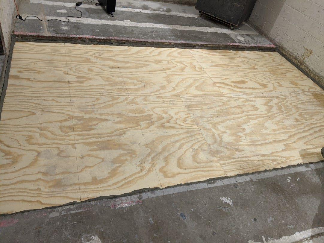
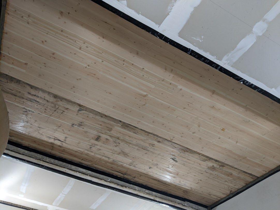
Page 6 of 16
University of Oregon
2024-06-24 Page 7 of 16
University of Oregon
2024-06-24 Page 8 of 16
University of Oregon
2024-06-24 Page 9 of 16
University of Oregon
2024-06-24 Page 10 of 16
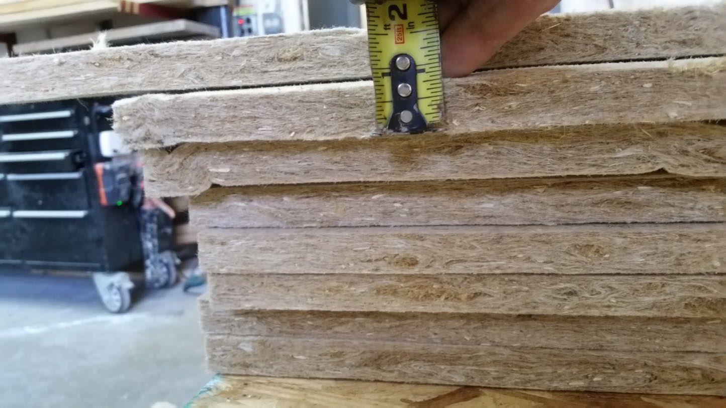
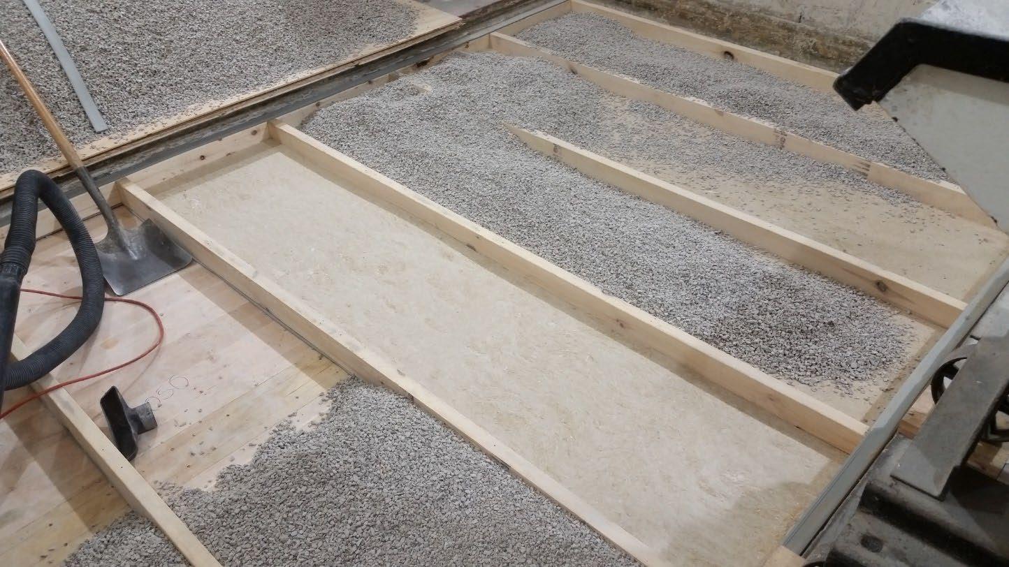
University of Oregon
2024-06-24 Page 11 of 16

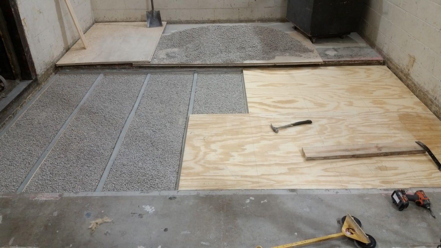
University of Oregon
2024-06-24 Page 12 of 16
The averaged sound pressure levels, normalized to a receive room reference absorption of 10 m2, are tabulated at the sixteen frequency bands specified in ASTM E492-22 Section 9.5. A graphic presentation of the data and additional information appear on the following pages. The 95% confidence limit for the sound pressure level in the receive room is below the limits specified in ASTM E492-22 Section A1.4.
IIC=49
ABBREVIATION INDEX
FREQ. = 1/3 OCTAVE BAND CENTER FREQUENCY, Hz
Ln = NORMALIZED SOUND PRESSURE LEVEL, dB
ΔLn = 95% UNCERTAINTY LIMIT FOR Ln, dB
DEV. = DEVIATION FROM SHIFTED IIC CONTOUR, dB (SUM OF DEV = 27 ) IIC = IMPACT INSULATION CLASS
= LEVEL CORRECTED DUE TO BACKGROUND NOISE PER E492 SEC 10.2.2
= LEVEL CORRECTED DUE TO BACKGROUND NOISE
Keith Kimberling
Keith Kimberling Test Engineer Test Engineer
Tested by______________________________ Report by__________________________
Approved by_______________________
Laboratory Manager
627 RIVERBANK DRIVE GENEVA, IL 60134
630-232-0104
University of Oregon
2024-06-24 Page 13 of 16
1-1/8” T&G plywood subfloor screwed 24” OC with #9x3”, cavity filled with: 3” of 3/8” limestone chip and Hempitecture 3/4” hemp fiber board, 2x4 sleepers 24”OC with Rothoblaas Piano B acoustic strips stapled top/bottom, Vaagen Timbers 5-ply CLT 6.875”
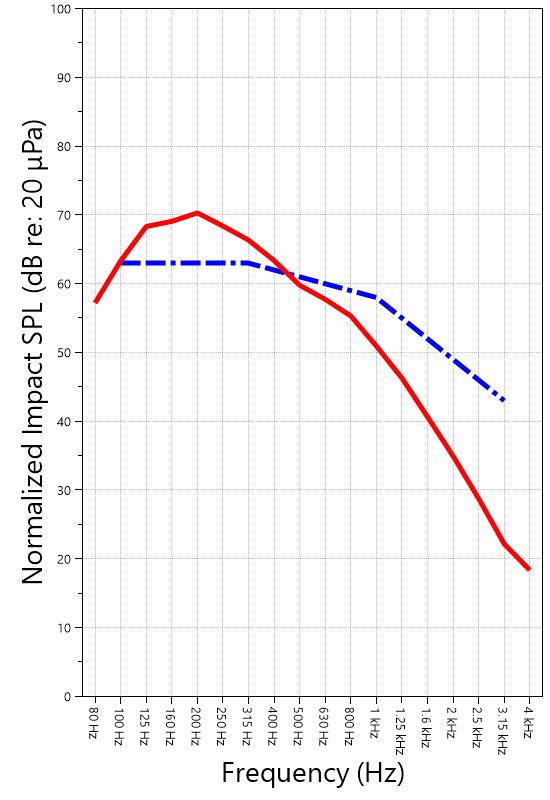
627 RIVERBANK DRIVE GENEVA, IL 60134
630-232-0104
University of Oregon
2024-06-24
Page 14 of 16
Specimen: 1-1/8” T&G plywood subfloor screwed 24” OC with #9x3”, cavity filled with: 3” of 3/8” limestone chip and Hempitecture 3/4” hemp fiber board, 2x4 sleepers 24”OC with Rothoblaas Piano B acoustic strips stapled top/bottom, Vaagen Timbers 5-ply CLT 6.875” (See Full Report)
The following non-accredited data were obtained in accordance with ASTM E492-22 but extend beyond the frequency range of 100 Hz to 3,150 Hz specified in Section 9.5. These unofficial results are representative of the RAL test environment only and intended for research & comparison purposes. 1/3 Octave Band
* Level corrected due to proximity to background noise per E492 Section 10.2.2
** Level corrected due to proximity to background noise per E492 Section 10.2.3, represents lower bound of specimen performance
627 RIVERBANK DRIVE GENEVA, IL 60134 630-232-0104
University of Oregon
2024-06-24
Page 15 of 16
Specimen: 1-1/8” T&G plywood subfloor screwed 24” OC with #9x3”, cavity filled with: 3” of 3/8” limestone chip and Hempitecture 3/4” hemp fiber board, 2x4 sleepers 24”OC with Rothoblaas Piano B acoustic strips stapled top/bottom, Vaagen Timbers 5-ply CLT 6.875” (See Full Report)
ΔLn, the 95% confidence limit for the reported normalized sound pressure level, is calculated from the standard deviation of the set of sound pressure levels measured during this individual test. This metric is calculated in an effort to quantify the variability in measured levels due to the combined influences of varying sound pressure level in the receive room and changes in specimen response for different tapping machine locations.
Repeatability, expressed as a 95% confidence limit, is calculated from the standard deviation in normalized sound pressure level as obtained from a total of six consecutive tests conducted according to this test method by RAL from 2019-02-07 to 2019-02-12. The tests were performed on a specimen composed of 152.4 mm (6 in.) thick concrete slabs, which was left installed and unaltered between tests. This metric provides an estimate of the variation in results that might be observed if the test were repeated with no change to the installed specimen. Note that repeatability will vary with the construction type.
Specimen: 1-1/8” T&G plywood subfloor screwed 24” OC with #9x3”, cavity filled with: 3” of 3/8” limestone chip and Hempitecture 3/4” hemp fiber board, 2x4 sleepers 24”OC with Rothoblaas Piano B acoustic strips stapled top/bottom, Vaagen Timbers 5-ply CLT 6.875” (See Full Report)
Current priorities in the architectural acoustics community involve the development of impact insulation metrics corresponding to impact sources of varying frequency content. Standard Classification ASTM E3222-20a provides a method for calculating the High-Frequency Impact Insulation Class (HIIC), using normalized impact sound pressure level (Ln) data at frequency bands from 400 Hz to 3150 Hz. Standard Classification ASTM E3207-21 provides a method for calculating the Low-Frequency Impact Insulation Class (LIIC) uses normalized impact sound pressure level (Ln) data at frequency bands from 50 Hz to 80 Hz.
Low-frequency impact noise correlates to the “thudding” of footfalls on lightweight structures, while high-frequency sound correlates to sources including the impacts of hard-heeled shoes, dragging furniture, dog toenails, and objects dropped on hard-surfaced flooring. When presented alongside the IIC rating, The LIIC and HIIC ratings can be used to predict how the nature of an impact source will affect the response of the floor-ceiling construction. A summary of impact insulation ratings, as calculated from the test results, is given below.
University of Oregon RAL™-IN24-016 2024-06-24 Page 16 of 16
APPENDIX D: Instruments of Traceability
Specimen: 1-1/8” T&G plywood subfloor screwed 24” OC with #9x3”, cavity filled with: 3” of 3/8” limestone chip and Hempitecture 3/4” hemp fiber board, 2x4 sleepers 24”OC with Rothoblaas Piano B acoustic strips stapled top/bottom, Vaagen Timbers 5-ply CLT 6.875” (See Full Report)
Description
System 2 Type 3160-A-042 3160106974 2023-08-11 2024-08-11
Bruel & Kjaer Mic And Preamp C Type 4943-B-001 2311439 2024-03-29 2025-03-29
Bruel & Kjaer Tapping Machine Type 3207 3151105 2023-12-14 2024-12-14
Bruel & Kjaer Pistonphone Type 4228 2781248 2023-07-12 2024-07-12
EXTECH Hygro 959 SD700 A.099959 2024-03-29 2025-03-29
EXTECH Hygro 639 SD700 A.103639 2023-12-01 2024-12-01
APPENDIX E: Revisions to Original Test Report
Specimen: 1-1/8” T&G plywood subfloor screwed 24” OC with #9x3”, cavity filled with: 3” of 3/8” limestone chip and Hempitecture 3/4” hemp fiber board, 2x4 sleepers 24”OC with Rothoblaas Piano B acoustic strips stapled top/bottom, Vaagen Timbers 5-ply CLT 6.875” (See Full Report)
Date Revision
2024-07-31 Original report issued
2024-09-19 Page 16: Tapping machine added to instruments of traceability. -EPW
627 RIVERBANK DRIVE
GENEVA, IL 60134
630-232-0104
SPONSOR: University of Oregon Impact Sound Transmission Portland, OR RAL™-IN24-017
CONDUCTED: 2024-06-25 Page 1 of 19
ON: Marmoleum Decibel adhered with Sustain 1195, 1-1/8” T&G plywood subfloor screwed 24” OC with #9x3”, cavity filled with: 3” of 3/8” limestone chip and Hempitecture 3/4” hemp fiber board, 2x4 sleepers 24”OC with Rothoblaas Piano B acoustic strips stapled top/bottom, Vaagen Timbers 5-ply CLT 6.875” with plywood spline 3/4”x6” at the joint secured with #9x3” screws at 6” OC
Riverbank Acoustical Laboratories™ is accredited by the U.S. Department of Commerce, National Institute of Standards and Technology (NIST) under the National Voluntary Laboratory Accreditation Program (NVLAP) as an ISO 17025:2017 Laboratory (NVLAP Lab Code: 100227-0) and for this test procedure. The test reported in this document conformed explicitly with ASTM E492-22: "Standard Test Method for Laboratory Measurement of Impact Sound Transmission Through Floor-Ceiling Assemblies Using the Tapping Machine." The single-number rating of the specimen was calculated according to ASTM E989-21: "Standard Classification for Determination of Single-Number Metrics for Impact Noise." A description of the measurement procedure and room specifications are available upon request. The results presented in this report apply to the individual test specimen as described and assembled.
The test specimen was designated by the sponsor as Marmoleum Decibel adhered with Sustain 1195, 11/8” T&G plywood subfloor screwed 24” OC with #9x3”, cavity filled with: 3” of 3/8” limestone chip and Hempitecture 3/4” hemp fiber board, 2x4 sleepers 24”OC with Rothoblaas Piano B acoustic strips stapled top/bottom, Vaagen Timbers 5-ply CLT 6.875” with plywood spline 3/4”x6” at the joint secured with #9x3” screws at 6” OC. The following nominal product information was provided by the sponsor prior to testing. The accuracy of such sponsor-provided information can affect the validity of the test results.
Provided Description: Marmoleum Decibel adhered with Sustain 1195, 1-1/8” T&G plywood subfloor screwed 24” OC with #9x3", cavity filled with: 3” of 3/8" limestone chip and Hempitecture 3/4” hemp fiber board, 2x4 sleepers 24”OC with Rothoblaas Piano B acoustic strips stapled top/bottom, Vaagen Timbers 5-ply CLT 6.875” with plywood spline 3/4”x6” at the joint secured with #9x3” screws at 6” OC
Manufacturer: University of Oregon
University of Oregon
2024-06-25
Page 2 of 19
The building contractor (Seth Priser) and RAL staff compiled a detailed construction specification as follows:
Cross-Laminated Timber (CLT)
Materials: 5-Ply Cross-Laminated Timber
Dimensions: 2 panels @ 1219 mm (48 in.) by 4229 mm (166.5 in.)
Thickness: 171 mm (6.75 in.)
Overall Weight: 953.45 kg (2102 lbs)
Mass Per Unit Volume: 539 kg/m3 (33.7 lbs/ft3)
Installation: CLT panels laid on 152 mm (6 in.) wide knee walls in test opening and butted to one another without sealant/adhesive.
3/4”x3” Rabbet on top side of one edge of each panel where they butt allowing a loose spline (below) to insert and join the two
Materials: 3/4” x 6” plywood spline
Dimensions: 1 piece @ 151 mm (5.9375 in.) wide by 2438 mm (96 in.) 1 piece @ 151 mm (5.9375 in.) wide by 1791 mm (70.5 in.)
Thickness: 19 mm (0.75 in.)
Overall Weight: 6.46 kg (14.25 lbs)
Mass Per Unit Length: 1.53 kg/m (1.03 lbs/ft)
Installation: Set in Rabbets of both CLT’s and screwed in place.
Fasteners: WSV Bugle head sub-floor screws, length @ 76 mm (3 in.)
Fastener Spacing: 6” o.c. on a line 3” from each edge of the spline (Centered on the rabbet of the CLT)
Piano B 40/40 (Lower Layer)
Manufacturer: Rothoblaas
Dimensions: 2 strips @ 40 mm (1.5625 in.) wide by 4267 mm (168 in.) long 8 strips @ 2362 mm (93 in.) wide by 40 mm (1.5625 in.) long
Thickness: 6.76 mm (0.266 in.)
Overall Weight: 4.59 kg (10.125 lbs)
Mass Per Unit Volume: 624 kg/m3 (40.0 lbs/ft3)
Installation: Fastened to underside of 2” x 4” wood sleepers with staples
Fasteners: Arrow staples, length @ 13 mm (0.5 in.)
University of Oregon
2024-06-25
SPECIMEN MEASUREMENTS & TEST CONDITIONS (continued)
2” by 4” SPF Framing Sleepers
Materials: Nominal 2”x 4” framing lumber
Page 3 of 19
Dimensions: 2 pieces @ 38 mm (1.5 in.) wide by 4255 mm (167.5 in.) long
8 pieces @ 2369 mm (93.25 in.) wide by 38 mm (1.5 in.) long
Depth: 89 mm (3.5 in.)
Overall Weight: 49.33 kg (108.75 lbs)
Mass Per Unit Length: 1.80 kg/m (1.21 lbs/ft)
Installation: Sleepers laid over CLT, resting on lower layer Piano B 40/40
Longer sleepers parallel to CLT like a rim joist
Shorter sleepers set like floor joists between rim joists
Shorter sleepers spaced approx. 610 mm (24 in.) on center
Shorter sleepers fastened to longer sleepers with screws, 2 screws per connection point
Fasteners: WSV Bugle head sub-floor screws, length @ 76 mm (3 in.)
Piano B 40/40 (Upper Layer)
Manufacturer: Rothoblaas
Dimensions: 2 strips @ 40 mm (1.5625 in.) wide by 4267 mm (168 in.) long 8 strips @ 2362 mm (93 in.) wide by 40 mm (1.5625 in.) long
Thickness: 6.76 mm (0.266 in.)
Overall Weight: 4.59 kg (10.125 lbs)
Mass Per Unit Volume: 624 kg/m3 (40.0 lbs/ft3)
Installation: Fastened to top of 2” x 4” wood sleepers with staples
Fasteners: Arrow staples, length @ 13 mm (0.5 in.)
Hemp Board
Materials: 1” Hemp fiber board
Manufacturer: Hempitecture
Dimensions: 7 pieces @ 572 mm (22.5 in.) wide by 2369 mm (93.25 in.) long
Depth: 19 mm (0.75 in.)
Overall Weight: 24.38 kg (53.75 lbs)
Mass Per Unit Volume: 135 kg/m3 (8.43 lbs/ft3)
Installation: Friction fit between sleepers and on top of CLT
627 RIVERBANK DRIVE GENEVA, IL 60134
630-232-0104
University of Oregon
2024-06-25
SPECIMEN MEASUREMENTS & TEST CONDITIONS (continued)
Crushed Limestone
Materials: CA-16 3/8” chip crushed limestone
Page 4 of 19
Dimensions: 2438 mm (96 in.) wide by 4267 mm (168 in.) long, as installed
Depth: 70 mm (2.75 in.)
Overall Weight: 986.56 kg (2175 lbs)
Installation: Filled stone in above hemp board and between sleepers and used a screed to level to the top of the sleepers.
Plywood Subfloor
Materials: T&G Plywood
Dimensions: 1 piece @ 1219 mm (48 in.) wide by 1829 mm (72 in.)
1 piece @ 1219 mm (48 in.) wide by 2438 mm (96 in.)
1 piece @ 1219 mm (48 in.) wide by 1822 mm (71.75 in.)
1 piece @ 1219 mm (48 in.) wide by 2432 mm (95.75 in.)
Thickness: 29 mm (1.125 in.)
Overall Weight: 170.66 kg (376.25 lbs)
Mass Per Unit Volume: 575 kg/m3 (35.9 lbs/ft3)
Installation: Placed over upper layer Piano B 40/40 over sleepers Fastened to sleepers through Piano B 40/40 with screws Plywood piece joints staggered Fasteners: WSV Bugle head sub-floor screws, length @ 76 mm (3 in.) Fastener Spacing: 610 mm (24 in.) on center
Adhesive
Materials: Sustain 1195 Sheet and Tile adhesive
Manufacturer: Forbo
Dimensions: Approx. 2438 mm (96 in.) by 4267 mm (168 in.) as installed
Overall Weight: 5.44 kg (12 lbs)
Mass Per Unit Area: 0.52 kg/m2 (0.11 lbs/ft2)
Installation: Troweled directly to plywood with a 1/16x1/16x1/16 square notch trowel
Once troweled, adhesive was left “open” for 15 min to allow it to “tack” before flooring was installed.
627 RIVERBANK DRIVE GENEVA, IL 60134
630-232-0104
University of Oregon
2024-06-25
SPECIMEN MEASUREMENTS & TEST CONDITIONS (continued)
Flooring
Page 5 of 19
Materials: Marmoleum Decibel
Manufacturer: Forbo
Dimensions: 2 pieces @ 2007 mm (79 in.) by 2464 mm (97 in.)
1 piece @ 257 mm (10.125 in.) by 2438 mm (96 in.)
Thickness: 6 mm (0.25 in.)
Overall Weight: 32.21 kg (71 lbs)
Mass Per Unit Volume: 482 kg/m3 (30.1 lbs/ft3)
Installation: Two (2) 79” segments perpendicular to Plywood 10” strip to complete Joints staggered from parallel plywood joints by + 6”
Rolled with 100lb roller in each direction
University of Oregon
2024-06-25 Page 6 of 19
SPECIMEN MEASUREMENTS & TEST CONDITIONS (continued)
Overall Specimen Measurements
Dimensions: 2.44 m (96.0 in) wide by 3.86 m (152.0 in) long
Thickness: 0.31 m (12.125 in)
Weight: 2237.68 kg (4933.25 lbs)
Overall Area: 9.414 m² (101.33 ft²)
Mass per Unit Area: 215.06 kg/m² (44.05 lbs/ft²)
Test Aperture
Opening Size: 4.27 m (14.0 ft.) by 6.10 m (20 ft.)
Filler Wall: Yes
Aperture Size: 2.44 m (96.0 in) wide by 3.86 m (152.0 in) long
Transmission Area: 9.414 m² (101.33 ft²)
Sealed: Entire periphery (both sides) with dense mastic
Test Environment
Source Room
Volume: 131.12 m³
Temperature: 22.8 °C ± 0.0 °C
Relative Humidity: 62.5 % ± 1.0 %
Receive Room
Volume: 81.44 m³
Temperature: 22.2 °C ± 0.0 °C
Relative Humidity: 62.5 % ± 1.0 %
Requirements
Temperature: 22º C +/- 5° C, not more than 3° C change over all tests.
Relative Humidity: ≥ 30% RH; not more than +/- 3% change over all tests.
University of Oregon
2024-06-25 Page 7 of 19
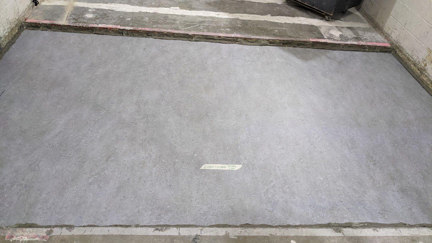
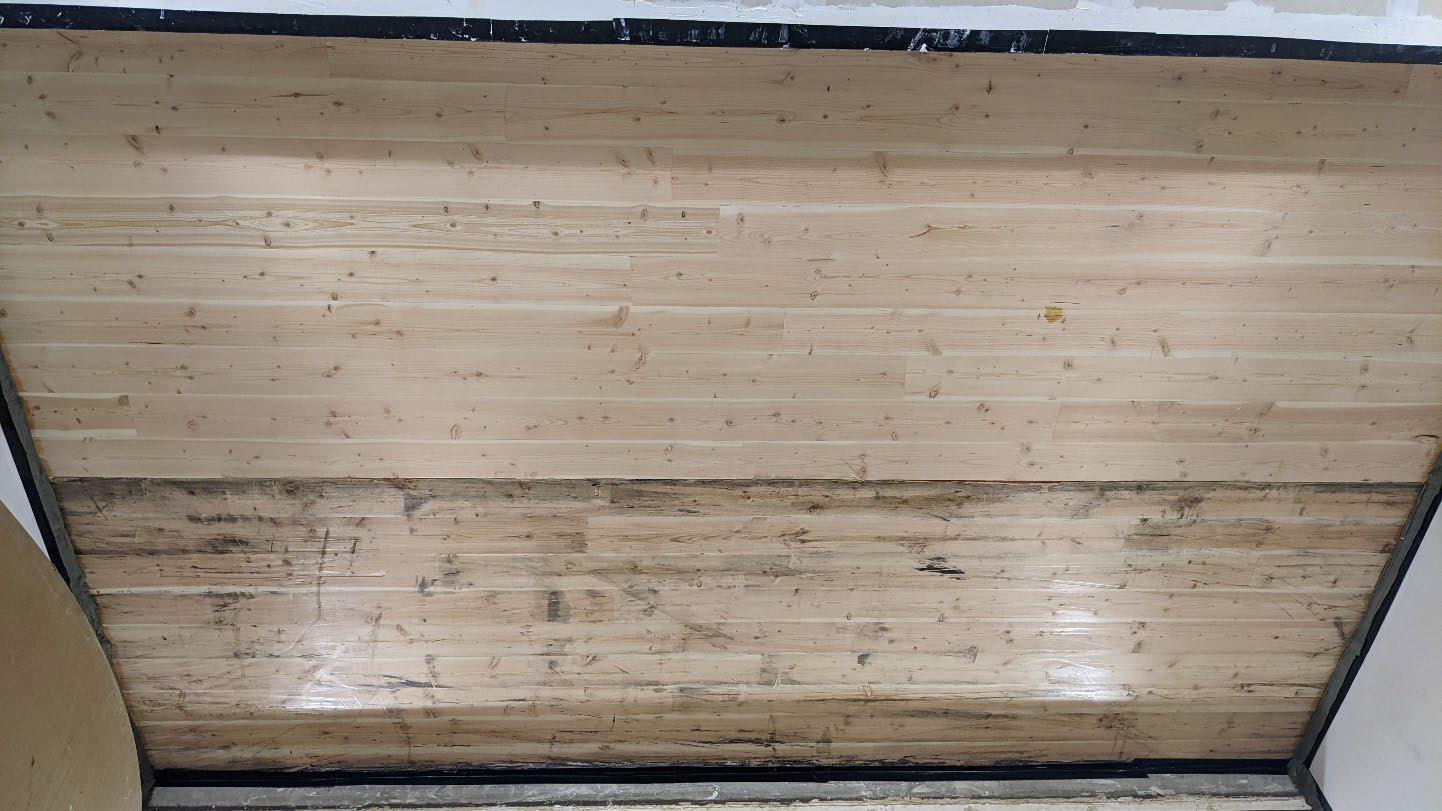
University of Oregon
2024-06-25 Page 8 of 19
University of Oregon
2024-06-25
Page 9 of 19
University of Oregon
2024-06-25 Page 10 of 19
University of Oregon
2024-06-25 Page 11 of 19
University of Oregon
2024-06-25 Page 12 of 19
University of Oregon
2024-06-25 Page 13 of 19
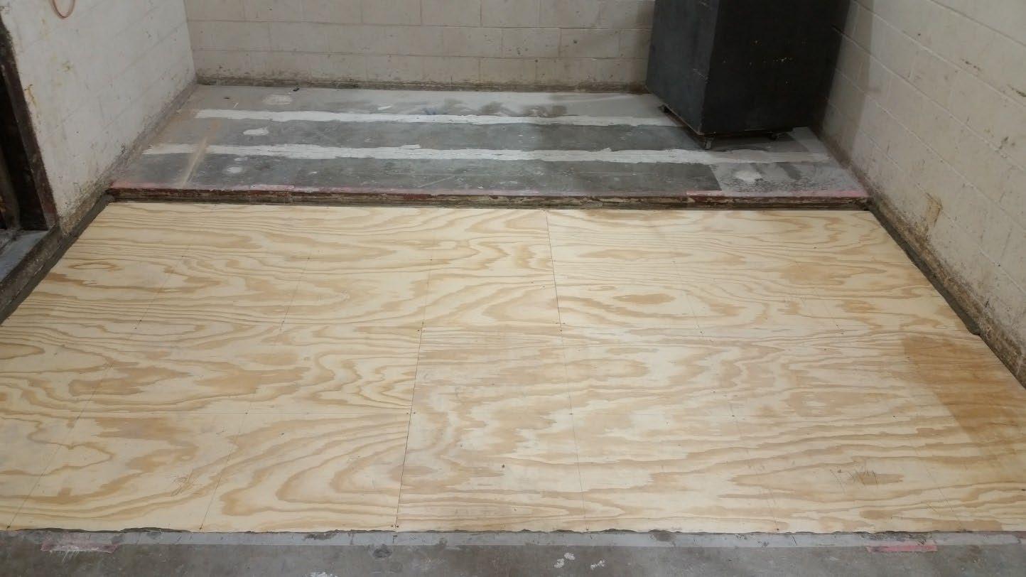
University of Oregon
2024-06-25 Page 14 of 19
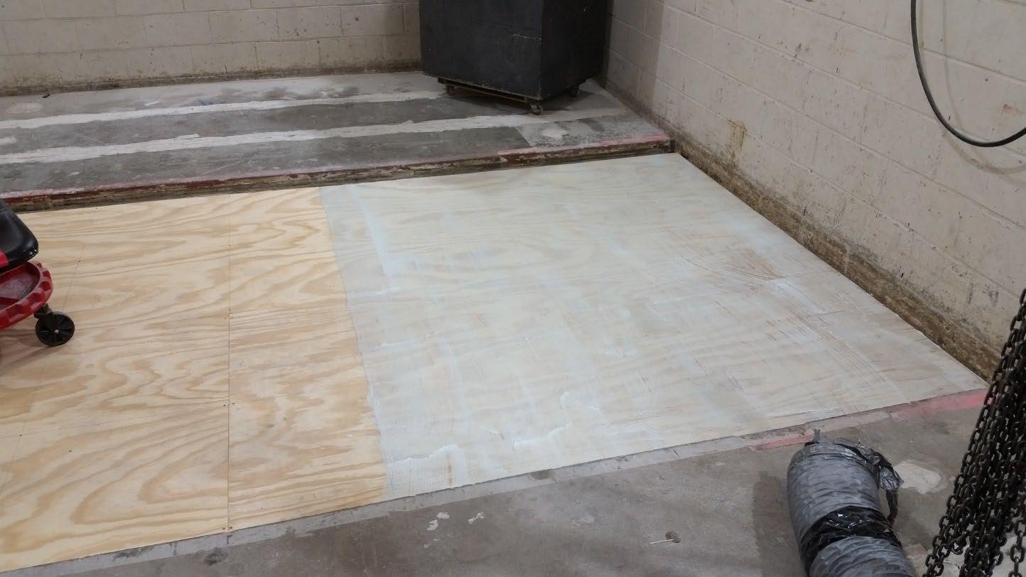
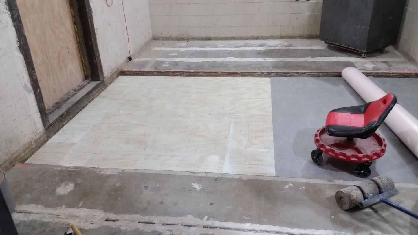
University of Oregon
2024-06-25 Page 15 of 19
The averaged sound pressure levels, normalized to a receive room reference absorption of 10 m2, are tabulated at the sixteen frequency bands specified in ASTM E492-22 Section 9.5. A graphic presentation of the data and additional information appear on the following pages. The 95% confidence limit for the sound pressure level in the receive room is below the limits specified in ASTM E492-22 Section A1.4.
IIC=49
ABBREVIATION INDEX
FREQ. = 1/3 OCTAVE BAND CENTER FREQUENCY, Hz
Ln = NORMALIZED SOUND PRESSURE LEVEL, dB
ΔLn = 95% UNCERTAINTY LIMIT FOR Ln, dB
DEV. = DEVIATION FROM SHIFTED IIC CONTOUR, dB (SUM OF DEV = 24 ) IIC = IMPACT INSULATION CLASS
LEVEL
Tested by______________________________ Report by__________________________
Keith Kimberling
Keith Kimberling Test Engineer Test Engineer
Approved by_______________________
Laboratory Manager
627 RIVERBANK DRIVE GENEVA, IL 60134 630-232-0104
University of Oregon
2024-06-25
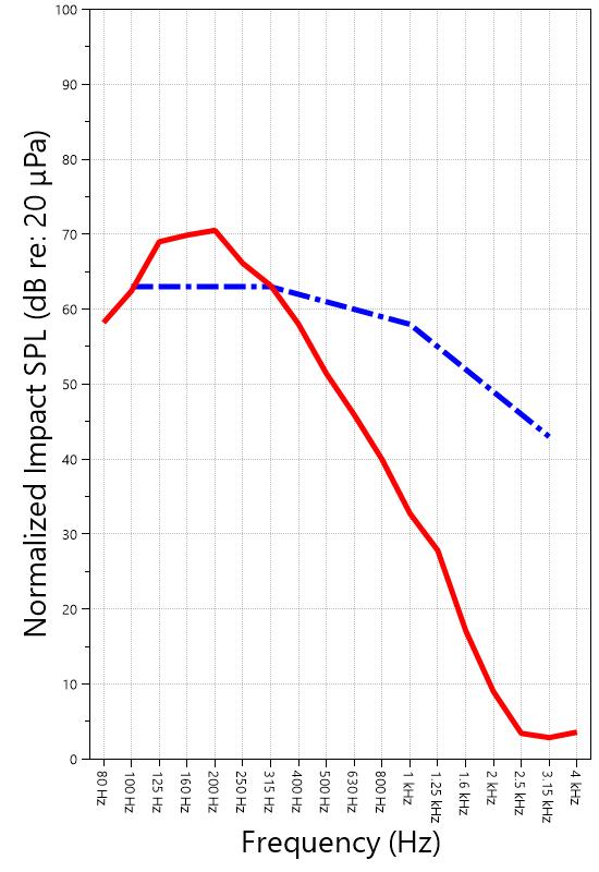
Page 16 of 19
Marmoleum Decibel adhered with Sustain 1195, 1-1/8” T&G plywood subfloor screwed 24” OC with #9x3”, cavity filled with: 3” of 3/8” limestone chip and Hempitecture 3/4” hemp fiber board, 2x4 sleepers 24”OC with Rothoblaas Piano B acoustic strips stapled top/bottom, Vaagen Timbers 5-ply CLT 6.875” with plywood spline 3/4”x6” at the joint secured with #9x3” screws at 6” OC IIC=49
IMPACT SOUND PRESSURE LEVEL
IMPACT INSULATION CLASS CONTOUR
627 RIVERBANK DRIVE GENEVA, IL 60134
630-232-0104
University of Oregon
2024-06-25
Page 17 of 19
Specimen: Marmoleum Decibel adhered with Sustain 1195, 1-1/8” T&G plywood subfloor screwed 24” OC with #9x3”, cavity filled with: 3” of 3/8” limestone chip and Hempitecture 3/4” hemp fiber board, 2x4 sleepers 24”OC with Rothoblaas Piano B acoustic strips stapled top/bottom, Vaagen Timbers 5-ply CLT 6.875” with plywood spline 3/4”x6” at the joint secured with #9x3” screws at 6” OC (See Full Report)
The following non-accredited data were obtained in accordance with ASTM E492-22 but extend beyond the frequency range of 100 Hz to 3,150 Hz specified in Section 9.5. These unofficial results are representative of the RAL test environment only and intended for research & comparison purposes.
1/3 Octave Band
* Level corrected due to proximity to background noise per E492 Section 10.2.2
** Level corrected due to proximity to background noise per E492 Section 10.2.3, represents lower bound of specimen performance
627 RIVERBANK DRIVE GENEVA, IL 60134 630-232-0104
University of Oregon
2024-06-25
Page 18 of 19
Specimen: Marmoleum Decibel adhered with Sustain 1195, 1-1/8” T&G plywood subfloor screwed 24” OC with #9x3”, cavity filled with: 3” of 3/8” limestone chip and Hempitecture 3/4” hemp fiber board, 2x4 sleepers 24”OC with Rothoblaas Piano B acoustic strips stapled top/bottom, Vaagen Timbers 5-ply CLT 6.875” with plywood spline 3/4”x6” at the joint secured with #9x3” screws at 6” OC (See Full Report)
ΔLn, the 95% confidence limit for the reported normalized sound pressure level, is calculated from the standard deviation of the set of sound pressure levels measured during this individual test. This metric is calculated in an effort to quantify the variability in measured levels due to the combined influences of varying sound pressure level in the receive room and changes in specimen response for different tapping machine locations.
Repeatability, expressed as a 95% confidence limit, is calculated from the standard deviation in normalized sound pressure level as obtained from a total of six consecutive tests conducted according to this test method by RAL from 2019-02-07 to 2019-02-12. The tests were performed on a specimen composed of 152.4 mm (6 in.) thick concrete slabs, which was left installed and unaltered between tests. This metric provides an estimate of the variation in results that might be observed if the test were repeated with no change to the installed specimen. Note that repeatability will vary with the construction type.
Specimen: Marmoleum Decibel adhered with Sustain 1195, 1-1/8” T&G plywood subfloor screwed 24” OC with #9x3”, cavity filled with: 3” of 3/8” limestone chip and Hempitecture 3/4” hemp fiber board, 2x4 sleepers 24”OC with Rothoblaas Piano B acoustic strips stapled top/bottom, Vaagen Timbers 5-ply CLT 6.875” with plywood spline 3/4”x6” at the joint secured with #9x3” screws at 6” OC (See Full Report)
Current priorities in the architectural acoustics community involve the development of impact insulation metrics corresponding to impact sources of varying frequency content. Standard Classification ASTM E3222-20a provides a method for calculating the High-Frequency Impact Insulation Class (HIIC), using normalized impact sound pressure level (Ln) data at frequency bands from 400 Hz to 3150 Hz. Standard Classification ASTM E3207-21 provides a method for calculating the Low-Frequency Impact Insulation Class (LIIC) uses normalized impact sound pressure level (Ln) data at frequency bands from 50 Hz to 80 Hz.
Low-frequency impact noise correlates to the “thudding” of footfalls on lightweight structures, while highfrequency sound correlates to sources including the impacts of hard-heeled shoes, dragging furniture, dog toenails, and objects dropped on hard-surfaced flooring. When presented alongside the IIC rating, The LIIC and HIIC ratings can be used to predict how the nature of an impact source will affect the response of the floor-ceiling construction. A summary of impact insulation ratings, as calculated from the test results, is given below.
627 RIVERBANK DRIVE GENEVA, IL 60134
University of Oregon RAL™-IN24-017 2024-06-25 Page 19 of 19
APPENDIX D: Instruments of Traceability
Specimen: Marmoleum Decibel adhered with Sustain 1195, 1-1/8” T&G plywood subfloor screwed 24” OC with #9x3”, cavity filled with: 3” of 3/8” limestone chip and Hempitecture 3/4” hemp fiber board, 2x4 sleepers 24”OC with Rothoblaas Piano B acoustic strips stapled top/bottom, Vaagen Timbers 5-ply CLT 6.875” with plywood spline 3/4”x6” at the joint secured with #9x3” screws at 6” OC (See Full Report)
Description
System 2
Type 3160-A-042 3160106974 2023-08-11 2024-08-11
Bruel & Kjaer Mic And Preamp C Type 4943-B-001 2311439 2024-03-29 2025-03-29
Bruel & Kjaer Tapping Machine Type 3207 3151105 2023-12-14 2024-12-14
Bruel & Kjaer Pistonphone Type 4228 2781248 2023-07-12 2024-07-12
EXTECH Hygro 959 SD700 A.099959 2024-03-29 2025-03-29
EXTECH Hygro 639 SD700 A.103639 2023-12-01 2024-12-01
APPENDIX E: Revisions to Original Test Report
Specimen: Marmoleum Decibel adhered with Sustain 1195, 1-1/8” T&G plywood subfloor screwed 24” OC with #9x3”, cavity filled with: 3” of 3/8” limestone chip and Hempitecture 3/4” hemp fiber board, 2x4 sleepers 24”OC with Rothoblaas Piano B acoustic strips stapled top/bottom, Vaagen Timbers 5-ply CLT 6.875” with plywood spline 3/4”x6” at the joint secured with #9x3” screws at 6” OC (See Full Report)
Date Revision
2024-07-31 Original report issued
2024-09-19 Page 19: Tapping machine added to instruments of traceability. -EPW
627 RIVERBANK DRIVE GENEVA, IL 60134 630-232-0104
www.riverbankacoustics.com FOUNDED 1918 BY WALLACE CLEMENT SABINE
SPONSOR: University of Oregon Impact Sound Transmission Portland, OR RAL™-IN24-018
CONDUCTED: 2024-06-26 Page 1 of 16
Riverbank Acoustical Laboratories™ is accredited by the U.S. Department of Commerce, National Institute of Standards and Technology (NIST) under the National Voluntary Laboratory Accreditation Program (NVLAP) as an ISO 17025:2017 Laboratory (NVLAP Lab Code: 100227-0) and for this test procedure. The test reported in this document conformed explicitly with ASTM E492-22: "Standard Test Method for Laboratory Measurement of Impact Sound Transmission Through Floor-Ceiling Assemblies Using the Tapping Machine." The single-number rating of the specimen was calculated according to ASTM E989-21: "Standard Classification for Determination of Single-Number Metrics for Impact Noise." A description of the measurement procedure and room specifications are available upon request. The results presented in this report apply to the individual test specimen as described and assembled.
INFORMATION PROVIDED BY SPONSOR
The test specimen was designated by the sponsor as 1-1/8” T&G plywood subfloor screwed 24” OC with #9x3”, cavity filled with: HempWool Acoustibatt 3.5” hemp batt, 2x4 sleepers 24”OC with Rothoblaas Piano B acoustic strips stapled top/bottom, Vaagen Timbers 5-ply CLT 6.875” with plywood spline 3/4”x6” at the joint secured with #9x3” screws at 6” OC. The following nominal product information was provided by the sponsor prior to testing. The accuracy of such sponsor-provided information can affect the validity of the test results.
Provided Description: 1-1/8” T&G plywood subfloor screwed 24” OC with #9x3", cavity filled with: HempWool Acoustibatt 3.5” hemp batt, 2x4 sleepers 24”OC with Rothoblaas Piano B acoustic strips stapled top/bottom, Vaagen Timbers 5-ply CLT 6.875” with plywood spline 3/4”x6” at the joint secured with #9x3” screws at 6” OC
Manufacturer: University of Oregon
ON: 1-1/8” T&G plywood subfloor screwed 24” OC with #9x3”, cavity filled with: HempWool Acoustibatt 3.5” hemp batt, 2x4 sleepers 24”OC with Rothoblaas Piano B acoustic strips stapled top/bottom, Vaagen Timbers 5-ply CLT 6.875” with plywood spline 3/4”x6” at the joint secured with #9x3” screws at 6” OC RIVERBANK ACOUSTICAL LABORATORIES IS ACCREDITED BY NVLAP (LAB CODE 100227-0) FOR ACOUSTICAL TESTING SERVICES IN ACCORDANCE WITH ISO/IEC 17025:2017 AND FOR THIS PROCEDURE. THIS REPORT MUST NOT BE USED BY THE CLIENT TO CLAIM
CERTIFICATION, APPROVAL, OR ENDORSEMENT BY RAL, NVLAP, NIST, OR ANY AGENCY OF THE U.S. GOVERNMENT. THIS REPORT SHALL NOT BE MODIFIED WITHOUT THE WRITTEN APPROVAL OF RAL. THE RESULTS REPORTED APPLY ONLY TO THE SPECIFIC SAMPLE SUBMITTED FOR TESTING; RAL ASSUMES NO RESPONSIBILITY FOR THE PERFORMANCE OF ANY OTHER SAMPLE
University of Oregon
2024-06-26
Page 2 of 16
The building contractor (Seth Priser) and RAL staff compiled a detailed construction specification as follows:
Cross-Laminated Timber (CLT)
Materials: 5-Ply Cross-Laminated Timber
Dimensions: 2 panels @ 1219 mm (48 in.) by 4229 mm (166.5 in.)
Thickness: 171 mm (6.75 in.)
Overall Weight: 953.45 kg (2102 lbs)
Mass Per Unit Volume: 539 kg/m3 (33.7 lbs/ft3)
Installation: CLT panels laid on 152 mm (6 in.) wide knee walls in test opening and butted to one another without sealant/adhesive.
3/4”x3” Rabbet on top side of one edge of each panel where they butt allowing a loose spline (below) to insert and join the two
Materials: 3/4” x 6” plywood spline
Dimensions: 1 piece @ 151 mm (5.9375 in.) wide by 2438 mm (96 in.) 1 piece @ 151 mm (5.9375 in.) wide by 1791 mm (70.5 in.)
Thickness: 19 mm (0.75 in.)
Overall Weight: 6.46 kg (14.25 lbs)
Mass Per Unit Length: 1.53 kg/m (1.03 lbs/ft)
Installation: Set in Rabbets of both CLT’s and screwed in place.
Fasteners: WSV Bugle head sub-floor screws, length @ 76 mm (3 in.)
Fastener Spacing: 6” o.c. on a line 3” from each edge of the spline (Centered on the rabbet of the CLT)
Piano B 40/40 (Lower Layer)
Manufacturer: Rothoblaas
Dimensions: 2 strips @ 40 mm (1.5625 in.) wide by 4267 mm (168 in.) long 8 strips @ 2362 mm (93 in.) wide by 40 mm (1.5625 in.) long
Thickness: 6.76 mm (0.266 in.)
Overall Weight: 4.59 kg (10.125 lbs)
Mass Per Unit Volume: 624 kg/m3 (40.0 lbs/ft3)
Installation: Fastened to underside of 2” x 4” wood sleepers with staples
Fasteners: Arrow staples, length @ 13 mm (0.5 in.)
University of Oregon
2024-06-26
SPECIMEN MEASUREMENTS & TEST CONDITIONS (continued)
2” by 4” SPF Framing Sleepers
Materials: Nominal 2”x 4” framing lumber
Page 3 of 16
Dimensions: 2 pieces @ 38 mm (1.5 in.) wide by 4255 mm (167.5 in.) long
8 pieces @ 2369 mm (93.25 in.) wide by 38 mm (1.5 in.) long
Depth: 89 mm (3.5 in.)
Overall Weight: 49.33 kg (108.75 lbs)
Mass Per Unit Length: 1.80 kg/m (1.21 lbs/ft)
Installation: Sleepers laid over CLT, resting on lower layer Piano B 40/40
Longer sleepers parallel to CLT like a rim joist
Shorter sleepers set like floor joists between rim joists
Shorter sleepers spaced approx. 610 mm (24 in.) on center
Shorter sleepers fastened to longer sleepers with screws, 2 screws per connection point
Fasteners: WSV Bugle head sub-floor screws, length @ 76 mm (3 in.)
Piano B 40/40 (Upper Layer)
Manufacturer: Rothoblaas
Dimensions: 2 strips @ 40 mm (1.5625 in.) wide by 4267 mm (168 in.) long 8 strips @ 2362 mm (93 in.) wide by 40 mm (1.5625 in.) long
Thickness: 6.76 mm (0.266 in.)
Overall Weight: 4.59 kg (10.125 lbs)
Mass Per Unit Volume: 624 kg/m3 (40.0 lbs/ft3)
Installation: Fastened to top of 2” x 4” wood sleepers with staples
Fasteners: Arrow staples, length @ 13 mm (0.5 in.)
Hemp Board
Materials: 3” Hemp fiber board
Manufacturer: Hempitecture
Dimensions: 7 pieces @ 572 mm (22.5 in.) wide by 2369 mm (93.25 in.) long
Depth: 76 mm (3 in.)
Overall Weight: 37.53 kg (82.75 lbs)
Mass Per Unit Volume: 52.0 kg/m3 (3.25 lbs/ft3)
Installation: Friction fit between sleepers and on top of CLT
University of Oregon
2024-06-26
SPECIMEN MEASUREMENTS & TEST CONDITIONS (continued)
Plywood Subfloor
Materials: T&G Plywood
Dimensions: 1 piece @ 1219 mm (48 in.) wide by 1829 mm (72 in.)
1 piece @ 1219 mm (48 in.) wide by 2438 mm (96 in.)
1 piece @ 1219 mm (48 in.) wide by 1822 mm (71.75 in.)
1 piece @ 1219 mm (48 in.) wide by 2432 mm (95.75 in.)
Thickness: 29 mm (1.125 in.)
Overall Weight: 172.25 kg (379.75 lbs)
Mass Per Unit Volume: 580 kg/m3 (36.2 lbs/ft3)
Installation: Placed over upper layer Piano B 40/40 over sleepers
Fastened to sleepers through Piano B 40/40 with screws
Plywood piece joints staggered
Fasteners: WSV Bugle head sub-floor screws, length @ 76 mm (3 in.)
Fastener Spacing: 610 mm (24 in.) on center
Page 4 of 16
University of Oregon
2024-06-26 Page 5 of 16
SPECIMEN MEASUREMENTS & TEST CONDITIONS (continued)
Overall Specimen Measurements
Dimensions: 2.44 m (96.0 in) wide by 3.86 m (152.0 in) long
Thickness: 0.3 m (11.875 in)
Weight: 1228.21 kg (2707.75 lbs)
Overall Area: 9.414 m² (101.33 ft²)
Mass per Unit Area: 118.04 kg/m² (24.18 lbs/ft²)
Test Aperture
Opening Size: 4.27 m (14.0 ft.) by 6.10 m (20 ft.)
Filler Wall: Yes
Aperture Size: 2.44 m (96.0 in) wide by 3.86 m (152.0 in) long
Transmission Area: 9.414 m² (101.33 ft²)
Sealed: Entire periphery (both sides) with dense mastic
Test Environment
Source Room
Volume: 131.12 m³
Temperature: 22.8 °C ± 0.0 °C
Relative Humidity: 65.0 % ± 0.0 %
Receive Room
Volume: 81.44 m³
Temperature: 22.2 °C ± 0.0 °C
Relative Humidity: 64.0 % ± 0.0 %
Requirements
Temperature: 22º C +/- 5° C, not more than 3° C change over all tests.
Relative Humidity: ≥ 30% RH; not more than +/- 3% change over all tests.
University of Oregon
2024-06-26 Page 6 of 16
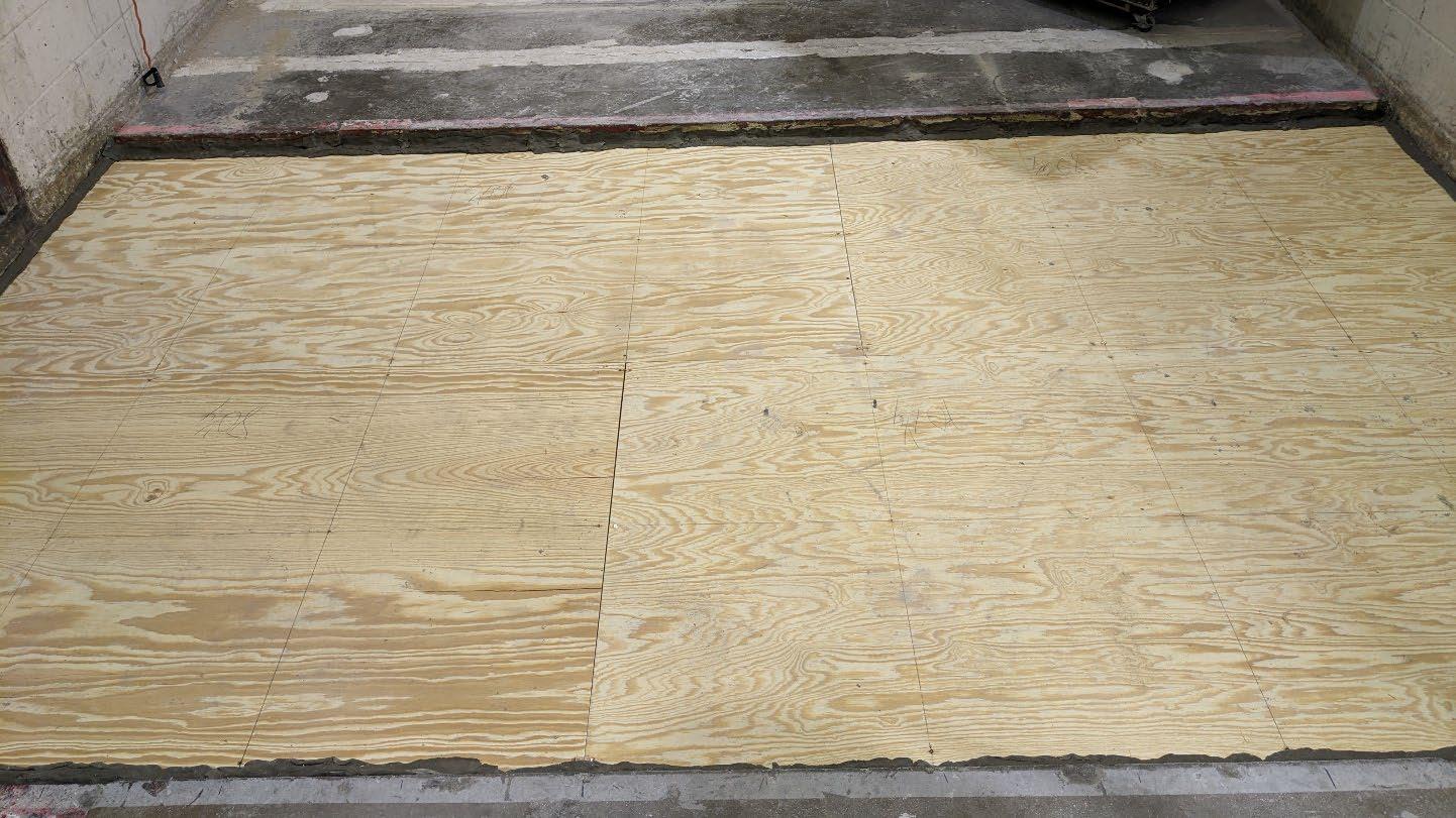
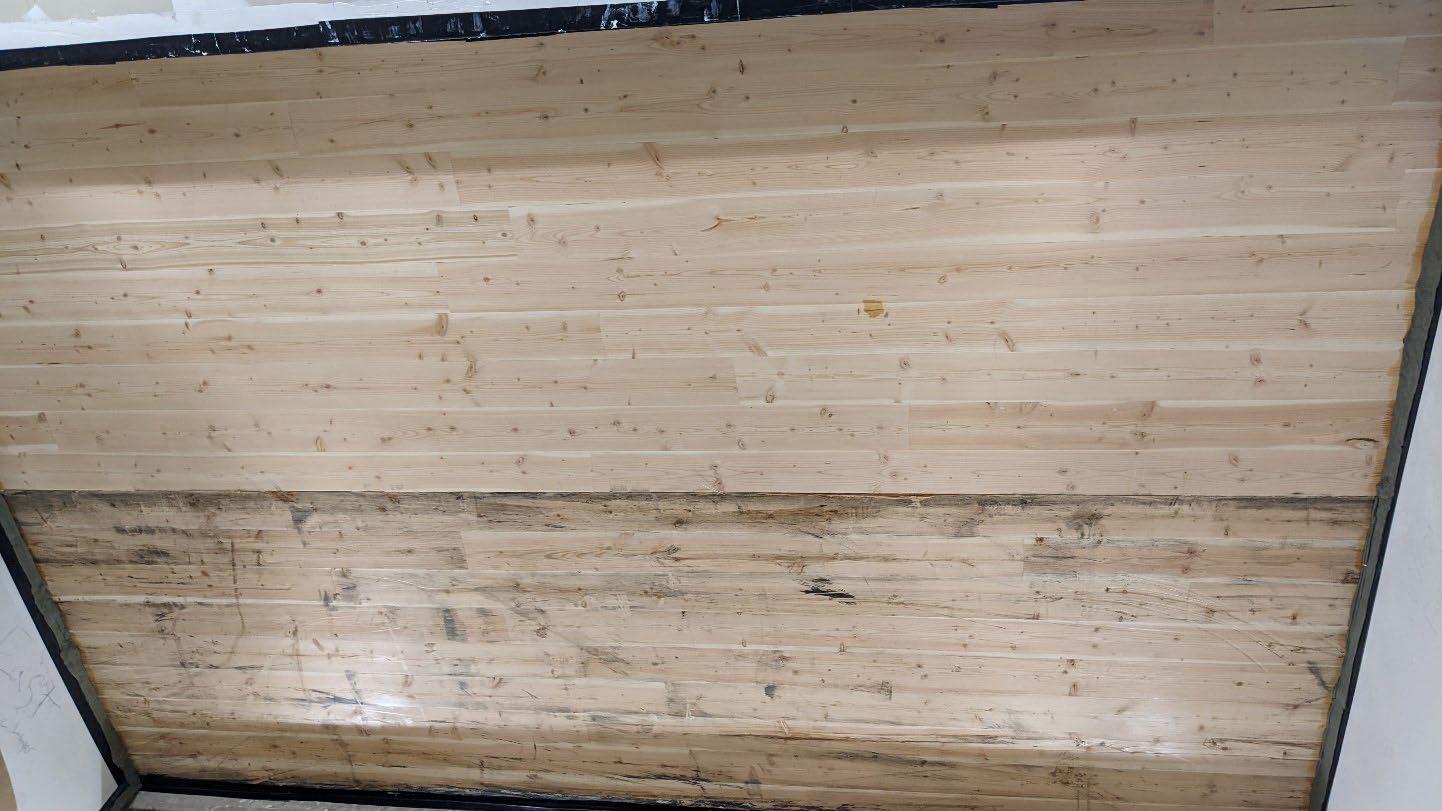
University of Oregon
2024-06-26 Page 7 of 16
University of Oregon
2024-06-26 Page 8 of 16
University of Oregon
2024-06-26 Page 9 of 16
University of Oregon
2024-06-26 Page 10 of 16
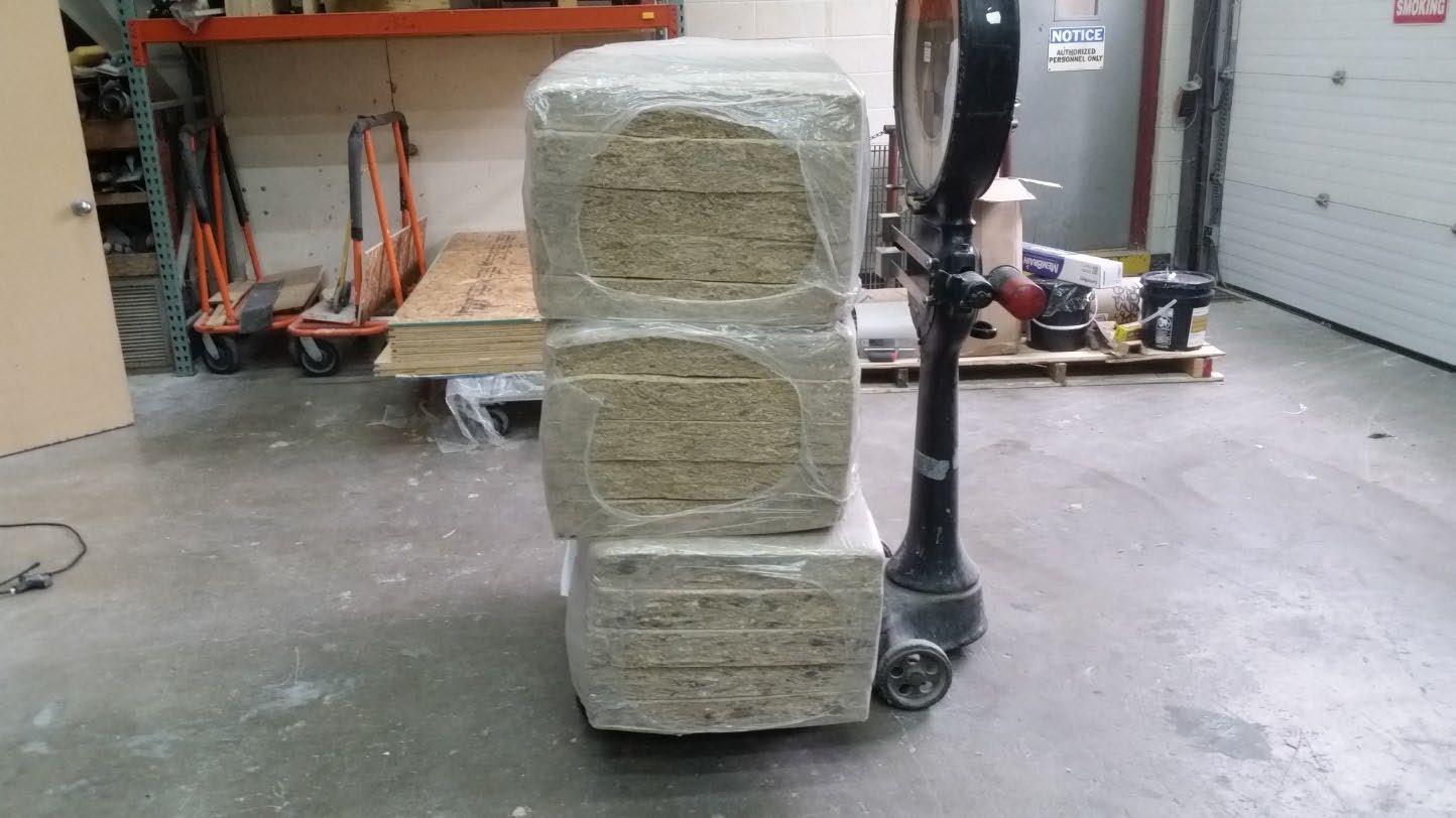
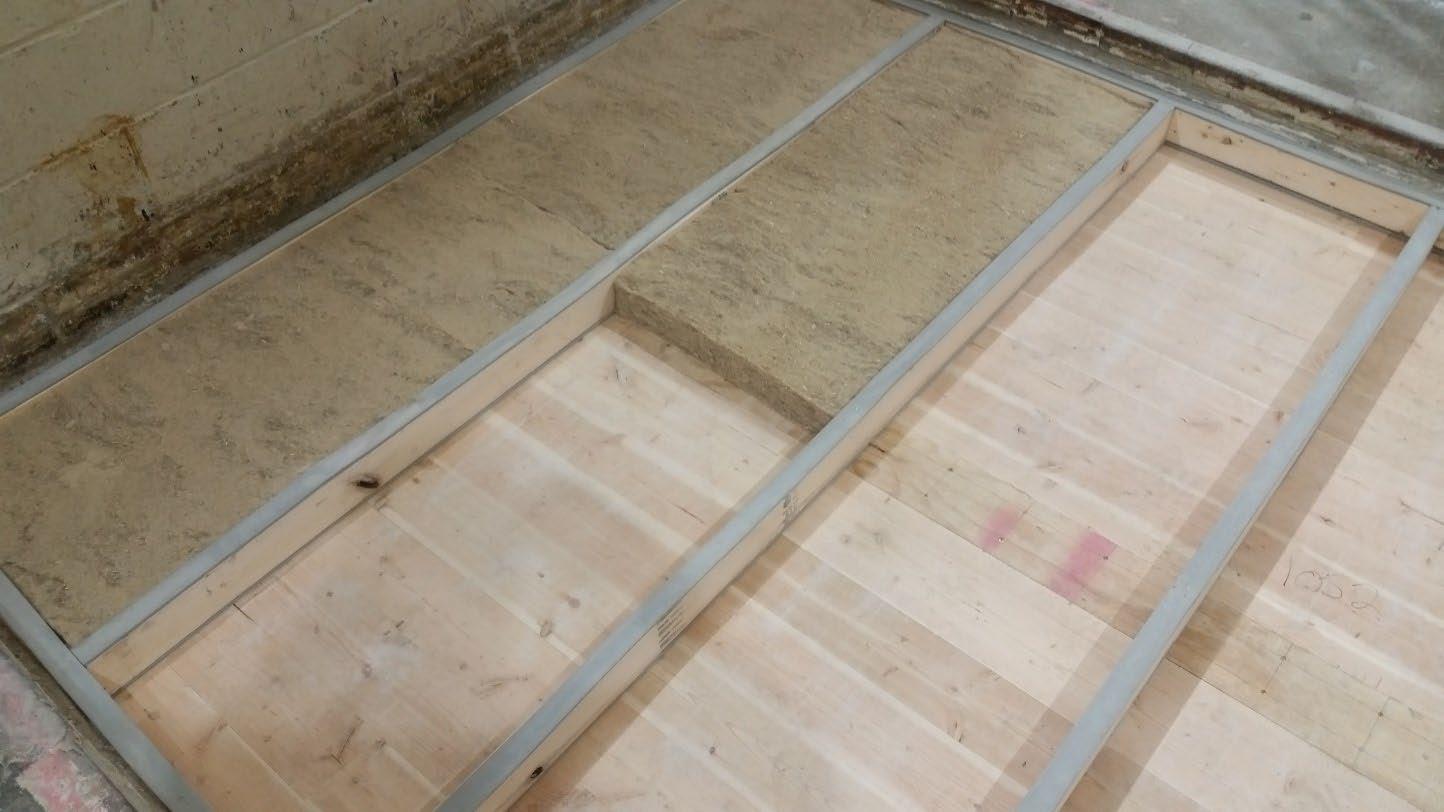
University of Oregon
2024-06-26 Page 11 of 16
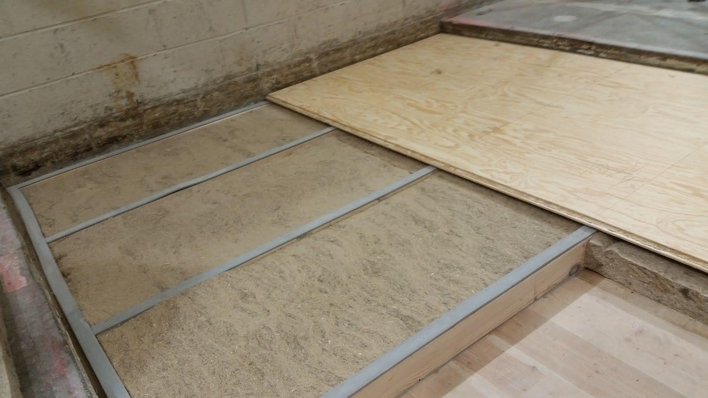
University of Oregon
2024-06-26 Page 12 of 16
The averaged sound pressure levels, normalized to a receive room reference absorption of 10 m2, are tabulated at the sixteen frequency bands specified in ASTM E492-22 Section 9.5. A graphic presentation of the data and additional information appear on the following pages. The 95% confidence limit for the sound pressure level in the receive room is below the limits specified in ASTM E492-22 Section A1.4.
IIC=49
ABBREVIATION INDEX
FREQ. = 1/3 OCTAVE BAND CENTER FREQUENCY, Hz
Ln = NORMALIZED SOUND PRESSURE LEVEL, dB
ΔLn = 95% UNCERTAINTY LIMIT FOR Ln, dB
DEV. = DEVIATION FROM SHIFTED IIC CONTOUR, dB (SUM OF DEV = 26 ) IIC = IMPACT INSULATION CLASS
= LEVEL CORRECTED DUE TO BACKGROUND NOISE PER E492 SEC 10.2.2
LEVEL CORRECTED DUE
Tested by______________________________ Report by__________________________
Keith Kimberling
Keith Kimberling Test Engineer Test Engineer
Approved by_______________________
Laboratory Manager
627 RIVERBANK DRIVE GENEVA, IL 60134 630-232-0104
University of Oregon
2024-06-26 Page 13 of 16
1-1/8” T&G plywood subfloor screwed 24” OC with #9x3”, cavity filled with: HempWool
Acoustibatt 3.5” hemp batt, 2x4 sleepers 24”OC with Rothoblaas Piano B acoustic strips stapled top/bottom, Vaagen Timbers 5-ply CLT 6.875” with plywood spline 3/4”x6” at the joint secured with #9x3” screws at 6” OC
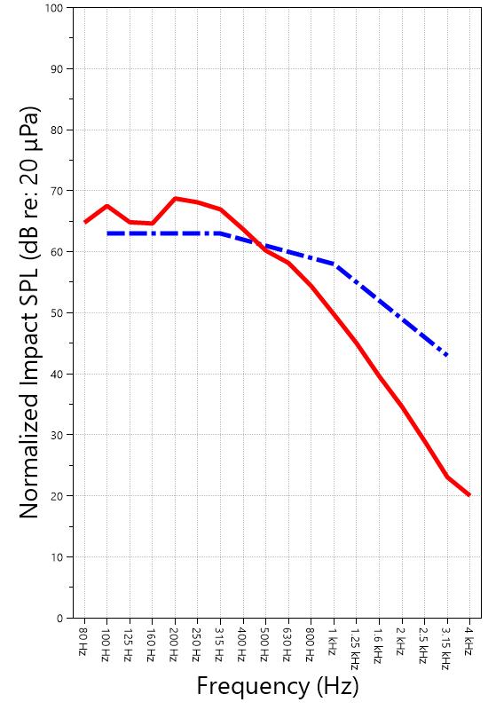
627 RIVERBANK DRIVE GENEVA, IL 60134 630-232-0104
University of Oregon
2024-06-26
Page 14 of 16
Specimen: 1-1/8” T&G plywood subfloor screwed 24” OC with #9x3”, cavity filled with: HempWool Acoustibatt 3.5” hemp batt, 2x4 sleepers 24”OC with Rothoblaas Piano B acoustic strips stapled top/bottom, Vaagen Timbers 5-ply CLT 6.875” with plywood spline 3/4”x6” at the joint secured with #9x3” screws at 6” OC (See Full Report)
The following non-accredited data were obtained in accordance with ASTM E492-22 but extend beyond the frequency range of 100 Hz to 3,150 Hz specified in Section 9.5. These unofficial results are representative of the RAL test environment only and intended for research & comparison purposes.
1/3 Octave Band
* Level corrected due to proximity to background noise per E492 Section 10.2.2
** Level corrected due to proximity to background noise per E492 Section 10.2.3, represents lower bound of specimen performance
627 RIVERBANK DRIVE GENEVA, IL 60134 630-232-0104
University of Oregon
2024-06-26
Page 15 of 16
Specimen: 1-1/8” T&G plywood subfloor screwed 24” OC with #9x3”, cavity filled with: HempWool Acoustibatt 3.5” hemp batt, 2x4 sleepers 24”OC with Rothoblaas Piano B acoustic strips stapled top/bottom, Vaagen Timbers 5-ply CLT 6.875” with plywood spline 3/4”x6” at the joint secured with #9x3” screws at 6” OC (See Full Report)
ΔLn, the 95% confidence limit for the reported normalized sound pressure level, is calculated from the standard deviation of the set of sound pressure levels measured during this individual test. This metric is calculated in an effort to quantify the variability in measured levels due to the combined influences of varying sound pressure level in the receive room and changes in specimen response for different tapping machine locations.
Repeatability, expressed as a 95% confidence limit, is calculated from the standard deviation in normalized sound pressure level as obtained from a total of six consecutive tests conducted according to this test method by RAL from 2019-02-07 to 2019-02-12. The tests were performed on a specimen composed of 152.4 mm (6 in.) thick concrete slabs, which was left installed and unaltered between tests. This metric provides an estimate of the variation in results that might be observed if the test were repeated with no change to the installed specimen. Note that repeatability will vary with the construction type.
Specimen: 1-1/8” T&G plywood subfloor screwed 24” OC with #9x3”, cavity filled with: HempWool Acoustibatt 3.5” hemp batt, 2x4 sleepers 24”OC with Rothoblaas Piano B acoustic strips stapled top/bottom, Vaagen Timbers 5-ply CLT 6.875” with plywood spline 3/4”x6” at the joint secured with #9x3” screws at 6” OC (See Full Report)
Current priorities in the architectural acoustics community involve the development of impact insulation metrics corresponding to impact sources of varying frequency content. Standard Classification ASTM E3222-20a provides a method for calculating the High-Frequency Impact Insulation Class (HIIC), using normalized impact sound pressure level (Ln) data at frequency bands from 400 Hz to 3150 Hz. Standard Classification ASTM E3207-21 provides a method for calculating the Low-Frequency Impact Insulation Class (LIIC) uses normalized impact sound pressure level (Ln) data at frequency bands from 50 Hz to 80 Hz.
Low-frequency impact noise correlates to the “thudding” of footfalls on lightweight structures, while highfrequency sound correlates to sources including the impacts of hard-heeled shoes, dragging furniture, dog toenails, and objects dropped on hard-surfaced flooring. When presented alongside the IIC rating, The LIIC and HIIC ratings can be used to predict how the nature of an impact source will affect the response of the floor-ceiling construction. A summary of impact insulation ratings, as calculated from the test results, is given below.
627 RIVERBANK DRIVE GENEVA, IL 60134 630-232-0104
University of Oregon
2024-06-26 Page 16 of 16
APPENDIX D: Instruments of Traceability
Specimen: 1-1/8” T&G plywood subfloor screwed 24” OC with #9x3”, cavity filled with: HempWool
Acoustibatt 3.5” hemp batt, 2x4 sleepers 24”OC with Rothoblaas Piano B acoustic strips stapled top/bottom, Vaagen Timbers 5-ply CLT 6.875” with plywood spline 3/4”x6” at the joint secured with #9x3” screws at 6” OC (See Full Report)
Description Model
Date of Certification Calibration Due
System 2 Type 3160-A-042 3160106974 2023-08-11 2024-08-11
Bruel & Kjaer Mic And Preamp C Type 4943-B-001 2311439 2024-03-29 2025-03-29
Bruel & Kjaer Tapping Machine Type 3207 3151105 2023-12-14 2024-12-14
Bruel & Kjaer Pistonphone Type 4228 2781248 2023-07-12 2024-07-12
EXTECH Hygro 959 SD700 A.099959 2024-03-29 2025-03-29
EXTECH Hygro 639 SD700 A.103639 2023-12-01 2024-12-01
APPENDIX E: Revisions to Original Test Report
Specimen: 1-1/8” T&G plywood subfloor screwed 24” OC with #9x3”, cavity filled with: HempWool
Acoustibatt 3.5” hemp batt, 2x4 sleepers 24”OC with Rothoblaas Piano B acoustic strips stapled top/bottom, Vaagen Timbers 5-ply CLT 6.875” with plywood spline 3/4”x6” at the joint secured with #9x3” screws at 6” OC (See Full Report)
Date Revision
2024-07-31 Original report issued
2024-09-19 Page 16: Tapping machine added to instruments of traceability -EPW
627 RIVERBANK DRIVE
GENEVA, IL 60134
630-232-0104
www.riverbankacoustics.com
SPONSOR: University of Oregon Impact Sound Transmission Portland, OR RAL™-IN24-019
CONDUCTED: 2024-06-28 Page 1 of 17
ON: Marmoleum Decibel adhered with Sustain 1195, 1-1/8” T&G plywood subfloor screwed 24” OC with #9x3”, cavity filled with: HempWool Acoustibatt 3.5” hemp batt, 2x4 sleepers 24”OC with Rothoblaas Piano B acoustic strips stapled top/bottom, Vaagen Timbers 5-ply CLT 6.875” with plywood spline 3/4”x6” at the joint secured with #9x3” screws at 6” OC
Riverbank Acoustical Laboratories™ is accredited by the U.S. Department of Commerce, National Institute of Standards and Technology (NIST) under the National Voluntary Laboratory Accreditation Program (NVLAP) as an ISO 17025:2017 Laboratory (NVLAP Lab Code: 100227-0) and for this test procedure. The test reported in this document conformed explicitly with ASTM E492-22: "Standard Test Method for Laboratory Measurement of Impact Sound Transmission Through Floor-Ceiling Assemblies Using the Tapping Machine." The single-number rating of the specimen was calculated according to ASTM E989-21: "Standard Classification for Determination of Single-Number Metrics for Impact Noise." A description of the measurement procedure and room specifications are available upon request. The results presented in this report apply to the individual test specimen as described and assembled.
The test specimen was designated by the sponsor as Marmoleum Decibel adhered with Sustain 1195, 11/8” T&G plywood subfloor screwed 24” OC with #9x3”, cavity filled with: HempWool Acoustibatt 3.5” hemp batt, 2x4 sleepers 24”OC with Rothoblaas Piano B acoustic strips stapled top/bottom, Vaagen Timbers 5-ply CLT 6.875” with plywood spline 3/4”x6” at the joint secured with #9x3” screws at 6” OC. The following nominal product information was provided by the sponsor prior to testing. The accuracy of such sponsor-provided information can affect the validity of the test results.
Product
Provided Description: Marmoleum Decibel adhered with Sustain 1195, 1-1/8” T&G plywood subfloor screwed 24” OC with #9x3", cavity filled with: HempWool Acoustibatt 3.5” hemp batt, 2x4 sleepers 24”OC with Rothoblaas
Piano B acoustic strips stapled top/bottom, Vaagen Timbers 5-ply CLT 6.875” with plywood spline 3/4”x6” at the joint secured with #9x3” screws at 6” OC
Manufacturer: University of Oregon
University of Oregon
2024-06-28
Page 2 of 17
The building contractor (Seth Priser) and RAL staff compiled a detailed construction specification as follows:
Cross-Laminated Timber (CLT)
Materials: 5-Ply Cross-Laminated Timber
Dimensions: 2 panels @ 1219 mm (48 in.) by 4229 mm (166.5 in.)
Thickness: 171 mm (6.75 in.)
Overall Weight: 953.45 kg (2102 lbs)
Mass Per Unit Volume: 539 kg/m3 (33.7 lbs/ft3)
Installation: CLT panels laid on 152 mm (6 in.) wide knee walls in test opening and butted to one another without sealant/adhesive.
3/4”x3” Rabbet on top side of one edge of each panel where they butt allowing a loose spline (below) to insert and join the two
Materials: 3/4” x 6” plywood spline
Dimensions: 1 piece @ 151 mm (5.9375 in.) wide by 2438 mm (96 in.) 1 piece @ 151 mm (5.9375 in.) wide by 1791 mm (70.5 in.)
Thickness: 19 mm (0.75 in.)
Overall Weight: 6.46 kg (14.25 lbs)
Mass Per Unit Length: 1.53 kg/m (1.03 lbs/ft)
Installation: Set in Rabbets of both CLT’s and screwed in place.
Fasteners: WSV Bugle head sub-floor screws, length @ 76 mm (3 in.)
Fastener Spacing: 6” o.c. on a line 3” from each edge of the spline (Centered on the rabbet of the CLT)
Piano B 40/40 (Lower Layer)
Manufacturer: Rothoblaas
Dimensions: 2 strips @ 40 mm (1.5625 in.) wide by 4267 mm (168 in.) long 8 strips @ 2362 mm (93 in.) wide by 40 mm (1.5625 in.) long
Thickness: 6.76 mm (0.266 in.)
Overall Weight: 4.59 kg (10.125 lbs)
Mass Per Unit Volume: 624 kg/m3 (40.0 lbs/ft3)
Installation: Fastened to underside of 2” x 4” wood sleepers with staples
Fasteners: Arrow staples, length @ 13 mm (0.5 in.)
University of Oregon
2024-06-28
SPECIMEN MEASUREMENTS & TEST CONDITIONS (continued)
2” by 4” SPF Framing Sleepers
Materials: Nominal 2”x 4” framing lumber
Page 3 of 17
Dimensions: 2 pieces @ 38 mm (1.5 in.) wide by 4255 mm (167.5 in.) long
8 pieces @ 2369 mm (93.25 in.) wide by 38 mm (1.5 in.) long
Depth: 89 mm (3.5 in.)
Overall Weight: 49.33 kg (108.75 lbs)
Mass Per Unit Length: 1.80 kg/m (1.21 lbs/ft)
Installation: Sleepers laid over CLT, resting on lower layer Piano B 40/40
Longer sleepers parallel to CLT like a rim joist
Shorter sleepers set like floor joists between rim joists
Shorter sleepers spaced approx. 610 mm (24 in.) on center
Shorter sleepers fastened to longer sleepers with screws, 2 screws per connection point
Fasteners: WSV Bugle head sub-floor screws, length @ 76 mm (3 in.)
Piano B 40/40 (Upper Layer)
Manufacturer: Rothoblaas
Dimensions: 2 strips @ 40 mm (1.5625 in.) wide by 4267 mm (168 in.) long 8 strips @ 2362 mm (93 in.) wide by 40 mm (1.5625 in.) long
Thickness: 6.76 mm (0.266 in.)
Overall Weight: 4.59 kg (10.125 lbs)
Mass Per Unit Volume: 624 kg/m3 (40.0 lbs/ft3)
Installation: Fastened to top of 2” x 4” wood sleepers with staples
Fasteners: Arrow staples, length @ 13 mm (0.5 in.)
Hemp Board
Materials: 3” Hemp fiber board
Manufacturer: Hempitecture
Dimensions: 7 pieces @ 572 mm (22.5 in.) wide by 2369 mm (93.25 in.) long
Depth: 76 mm (3 in.)
Overall Weight: 37.53 kg (82.75 lbs)
Mass Per Unit Volume: 52.0 kg/m3 (3.25 lbs/ft3)
Installation: Friction fit between sleepers and on top of CLT
University of Oregon
2024-06-28
SPECIMEN MEASUREMENTS & TEST CONDITIONS (continued)
Plywood Subfloor
Materials: T&G Plywood
Dimensions: 1 piece @ 1219 mm (48 in.) wide by 1829 mm (72 in.)
1 piece @ 1219 mm (48 in.) wide by 2438 mm (96 in.)
1 piece @ 1219 mm (48 in.) wide by 1822 mm (71.75 in.)
1 piece @ 1219 mm (48 in.) wide by 2432 mm (95.75 in.)
Thickness: 29 mm (1.125 in.)
Overall Weight: 172.25 kg (379.75 lbs)
Mass Per Unit Volume: 580 kg/m3 (36.2 lbs/ft3)
Installation: Placed over upper layer Piano B 40/40 over sleepers
Fastened to sleepers through Piano B 40/40 with screws
Plywood piece joints staggered
Fasteners: WSV Bugle head sub-floor screws, length @ 76 mm (3 in.)
Fastener Spacing: 610 mm (24 in.) on center
Adhesive
Materials: Sustain 1195 Sheet and Tile adhesive
Manufacturer: Forbo
Dimensions: Approx. 2438 mm (96 in.) by 4267 mm (168 in.) as installed
Overall Weight: 4.2 kg (9.25 lbs)
Mass Per Unit Area: 0.40 kg/m2 (0.08 lbs/ft2)
Flooring
Page 4 of 17
Installation: Troweled directly to plywood with a 1/16x1/16x1/16 square notch trowel
Once troweled, adhesive was left “open” for 15 min to allow it to “tack” before flooring was installed.
Materials: Marmoleum Decibel
Manufacturer: Forbo
Dimensions: 2 pieces @ 2007 mm (79 in.) by 2464 mm (97 in.)
1 piece @ 257 mm (10.125 in.) by 2438 mm (96 in.)
Thickness: 6 mm (0.25 in.)
Overall Weight: 32.32 kg (71.25 lbs)
Mass Per Unit Volume: 484 kg/m3 (30.2 lbs/ft3)
Installation: Two (2) 79” segments perpendicular to Plywood 10” strip to complete Joints staggered from parallel plywood joints by + 6” Rolled with 100lb roller in each direction
University of Oregon
2024-06-28 Page 5 of 17
SPECIMEN MEASUREMENTS & TEST CONDITIONS (continued)
Overall Specimen Measurements
Dimensions: 2.44 m (96.0 in) wide by 3.86 m (152.0 in) long
Thickness: 0.31 m (12.125 in)
Weight: 1264.73 kg (2788.25 lbs)
Overall Area: 9.414 m² (101.33 ft²)
Mass per Unit Area: 121.55 kg/m² (24.90 lbs/ft²)
Test Aperture
Opening Size: 4.27 m (14.0 ft.) by 6.10 m (20 ft.)
Filler Wall: Yes
Aperture Size: 2.44 m (96.0 in) wide by 3.86 m (152.0 in) long
Transmission Area: 9.414 m² (101.33 ft²)
Sealed: Entire periphery (both sides) with dense mastic
Test Environment
Source Room
Volume: 131.12 m³
Temperature: 23.3 °C ± 0.0 °C
Relative Humidity: 60.0 % ± 0.0 %
Receive Room
Volume: 81.44 m³
Temperature: 22.2 °C ± 0.0 °C
Relative Humidity: 62.0 % ± 0.0 %
Requirements
Temperature: 22º C +/- 5° C, not more than 3° C change over all tests.
Relative Humidity: ≥ 30% RH; not more than +/- 3% change over all tests.
University of Oregon
2024-06-28
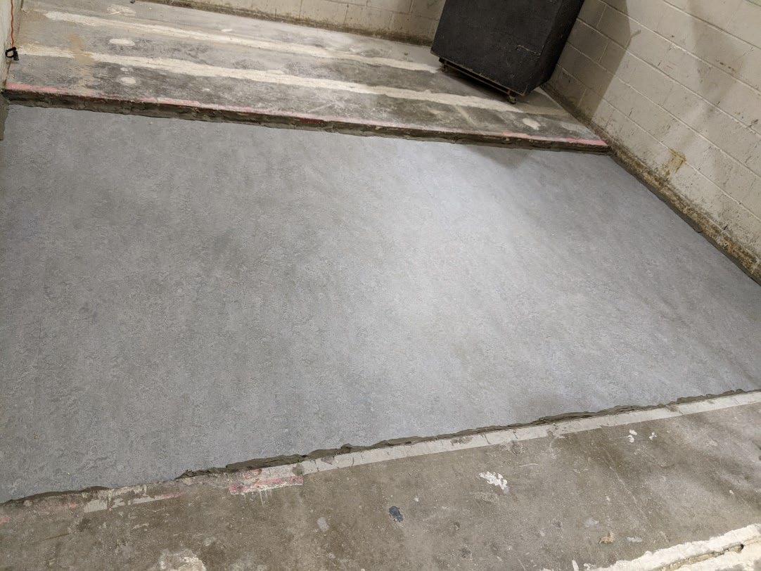
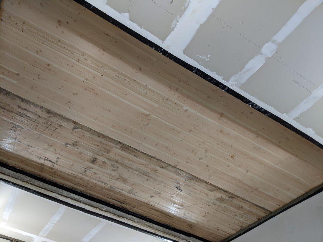
Page 6 of 17
University of Oregon
2024-06-28 Page 7 of 17
University of Oregon
2024-06-28 Page 8 of 17
University of Oregon
2024-06-28 Page 9 of 17
University of Oregon
2024-06-28 Page 10 of 17


University of Oregon
2024-06-28 Page 11 of 17

University of Oregon
2024-06-28 Page 12 of 17
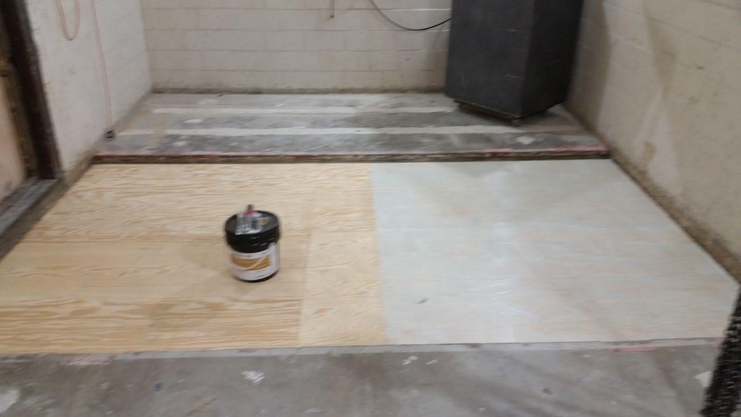
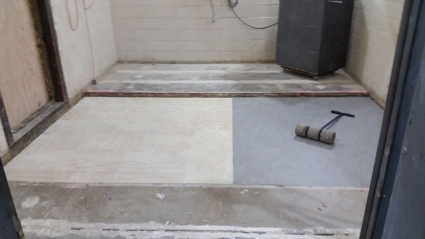
University of Oregon
2024-06-28 Page 13 of 17
The averaged sound pressure levels, normalized to a receive room reference absorption of 10 m2, are tabulated at the sixteen frequency bands specified in ASTM E492-22 Section 9.5. A graphic presentation of the data and additional information appear on the following pages. The 95% confidence limit for the sound pressure level in the receive room is below the limits specified in ASTM E492-22 Section A1.4.
IIC=50
ABBREVIATION INDEX
FREQ. = 1/3 OCTAVE BAND CENTER FREQUENCY, Hz
Ln = NORMALIZED SOUND PRESSURE LEVEL, dB
ΔLn = 95% UNCERTAINTY LIMIT FOR Ln, dB
DEV. = DEVIATION FROM SHIFTED IIC CONTOUR, dB (SUM OF DEV = 28 ) IIC = IMPACT INSULATION CLASS
LEVEL CORRECTED DUE TO
Keith Kimberling Senior Experimentalist Test Engineer
Tested by______________________________ Report by__________________________
Approved by_______________________
Laboratory Manager
627 RIVERBANK DRIVE GENEVA, IL 60134 630-232-0104
University of Oregon
2024-06-28
Page 14 of 17
Marmoleum Decibel adhered with Sustain 1195, 1-1/8” T&G plywood subfloor screwed 24” OC with #9x3”, cavity filled with: HempWool Acoustibatt 3.5” hemp batt, 2x4 sleepers 24”OC with Rothoblaas Piano B acoustic strips stapled top/bottom, Vaagen Timbers 5-ply CLT 6.875” with plywood spline 3/4”x6” at the joint secured with #9x3” screws at 6” OC
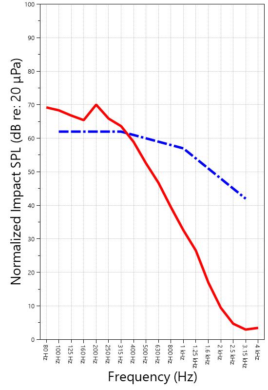
IMPACT SOUND PRESSURE LEVEL IMPACT INSULATION CLASS CONTOUR
627 RIVERBANK DRIVE GENEVA, IL 60134
630-232-0104
University of Oregon
2024-06-28
Page 15 of 17
Specimen: Marmoleum Decibel adhered with Sustain 1195, 1-1/8” T&G plywood subfloor screwed 24” OC with #9x3”, cavity filled with: HempWool Acoustibatt 3.5” hemp batt, 2x4 sleepers 24”OC with Rothoblaas Piano B acoustic strips stapled top/bottom, Vaagen Timbers 5-ply CLT 6.875” with plywood spline 3/4”x6” at the joint secured with #9x3” screws at 6” OC (See Full Report)
The following non-accredited data were obtained in accordance with ASTM E492-22 but extend beyond the frequency range of 100 Hz to 3,150 Hz specified in Section 9.5. These unofficial results are representative of the RAL test environment only and intended for research & comparison purposes. 1/3 Octave Band
* Level corrected due to proximity to background noise per E492 Section 10.2.2
** Level corrected due to proximity to background noise per E492 Section 10.2.3, represents lower bound of specimen performance
627 RIVERBANK DRIVE GENEVA, IL 60134 630-232-0104
University of Oregon
2024-06-28
Page 16 of 17
Specimen: Marmoleum Decibel adhered with Sustain 1195, 1-1/8” T&G plywood subfloor screwed 24” OC with #9x3”, cavity filled with: HempWool Acoustibatt 3.5” hemp batt, 2x4 sleepers 24”OC with Rothoblaas Piano B acoustic strips stapled top/bottom, Vaagen Timbers 5-ply CLT 6.875” with plywood spline 3/4”x6” at the joint secured with #9x3” screws at 6” OC (See Full Report)
ΔLn, the 95% confidence limit for the reported normalized sound pressure level, is calculated from the standard deviation of the set of sound pressure levels measured during this individual test. This metric is calculated in an effort to quantify the variability in measured levels due to the combined influences of varying sound pressure level in the receive room and changes in specimen response for different tapping machine locations.
Repeatability, expressed as a 95% confidence limit, is calculated from the standard deviation in normalized sound pressure level as obtained from a total of six consecutive tests conducted according to this test method by RAL from 2019-02-07 to 2019-02-12. The tests were performed on a specimen composed of 152.4 mm (6 in.) thick concrete slabs, which was left installed and unaltered between tests. This metric provides an estimate of the variation in results that might be observed if the test were repeated with no change to the installed specimen. Note that repeatability will vary with the construction type.
Specimen: Marmoleum Decibel adhered with Sustain 1195, 1-1/8” T&G plywood subfloor screwed 24” OC with #9x3”, cavity filled with: HempWool Acoustibatt 3.5” hemp batt, 2x4 sleepers 24”OC with Rothoblaas Piano B acoustic strips stapled top/bottom, Vaagen Timbers 5-ply CLT 6.875” with plywood spline 3/4”x6” at the joint secured with #9x3” screws at 6” OC (See Full Report)
Current priorities in the architectural acoustics community involve the development of impact insulation metrics corresponding to impact sources of varying frequency content. Standard Classification ASTM E3222-20a provides a method for calculating the High-Frequency Impact Insulation Class (HIIC), using normalized impact sound pressure level (Ln) data at frequency bands from 400 Hz to 3150 Hz. Standard Classification ASTM E3207-21 provides a method for calculating the Low-Frequency Impact Insulation Class (LIIC) uses normalized impact sound pressure level (Ln) data at frequency bands from 50 Hz to 80 Hz.
Low-frequency impact noise correlates to the “thudding” of footfalls on lightweight structures, while highfrequency sound correlates to sources including the impacts of hard-heeled shoes, dragging furniture, dog toenails, and objects dropped on hard-surfaced flooring. When presented alongside the IIC rating, The LIIC and HIIC ratings can be used to predict how the nature of an impact source will affect the response of the floor-ceiling construction. A summary of impact insulation ratings, as calculated from the test results, is given below.
RIVERBANK DRIVE GENEVA, IL 60134 630-232-0104
University of Oregon RAL™-IN24-019 2024-06-28 Page 17 of 17
APPENDIX D: Instruments of Traceability
Specimen: Marmoleum Decibel adhered with Sustain 1195, 1-1/8” T&G plywood subfloor screwed 24” OC with #9x3”, cavity filled with: HempWool Acoustibatt 3.5” hemp batt, 2x4 sleepers 24”OC with Rothoblaas Piano B acoustic strips stapled top/bottom, Vaagen Timbers 5-ply CLT 6.875” with plywood spline 3/4”x6” at the joint secured with #9x3” screws at 6” OC (See Full Report)
Description
System 2 Type 3160-A-042 3160106974 2023-08-11 2024-08-11
Bruel & Kjaer Mic And Preamp C Type 4943-B-001 2311439 2024-03-29 2025-03-29
Bruel & Kjaer Tapping Machine Type 3207 3151105 2023-12-14 2024-12-14
Bruel & Kjaer Pistonphone Type 4228 2781248 2023-07-12 2024-07-12
EXTECH Hygro 959 SD700 A.099959 2024-03-29 2025-03-29
EXTECH Hygro 639 SD700 A.103639 2023-12-01 2024-12-01
APPENDIX E: Revisions to Original Test Report
Specimen: Marmoleum Decibel adhered with Sustain 1195, 1-1/8” T&G plywood subfloor screwed 24” OC with #9x3”, cavity filled with: HempWool Acoustibatt 3.5” hemp batt, 2x4 sleepers 24”OC with Rothoblaas Piano B acoustic strips stapled top/bottom, Vaagen Timbers 5-ply CLT 6.875” with plywood spline 3/4”x6” at the joint secured with #9x3” screws at 6” OC (See Full Report)
Date Revision
2024-07-31 Original report issued
2024-09-19 Page 17: Tapping machine added to instruments of traceability. -EPW END
627 RIVERBANK DRIVE
GENEVA, IL 60134
630-232-0104
www.riverbankacoustics.com
SPONSOR: University of Oregon Impact Sound Transmission Portland, OR RAL™-IN24-020
CONDUCTED: 2024-07-08 Page 1 of 17
Riverbank Acoustical Laboratories™ is accredited by the U.S. Department of Commerce, National Institute of Standards and Technology (NIST) under the National Voluntary Laboratory Accreditation Program (NVLAP) as an ISO 17025:2017 Laboratory (NVLAP Lab Code: 100227-0) and for this test procedure. The test reported in this document conformed explicitly with ASTM E492-22: "Standard Test Method for Laboratory Measurement of Impact Sound Transmission Through Floor-Ceiling Assemblies Using the Tapping Machine." The single-number rating of the specimen was calculated according to ASTM E989-21: "Standard Classification for Determination of Single-Number Metrics for Impact Noise." A description of the measurement procedure and room specifications are available upon request. The results presented in this report apply to the individual test specimen as described and assembled.
The test specimen was designated by the sponsor as 1” Maxxon gypcrete 2000 Multifamily, 1-1/8” T&G plywood subfloor screwed 24” OC with #9x3”, cavity filled with: HempWool Acoustibatt 3.5” hemp batt, 2x4 sleepers 24”OC with Rothoblaas Piano B acoustic strips stapled top/bottom, Vaagen Timbers 5-ply CLT 6.875” with plywood spline 3/4”x6” at the joint secured with #9x3” screws at 6” OC. The following nominal product information was provided by the sponsor prior to testing. The accuracy of such sponsor-provided information can affect the validity of the test results.
Product Under Test
Provided Description: 1” Maxxon gypcrete 2000 Multifamily, 1-1/8” T&G plywood subfloor screwed 24” OC with #9x3", cavity filled with: HempWool
Acoustibatt 3.5” hemp batt, 2x4 sleepers 24”OC with Rothoblaas
Piano B acoustic strips stapled top/bottom, Vaagen Timbers 5-ply CLT 6.875” with plywood spline 3/4”x6” at the joint secured with #9x3” screws at 6” OC
Manufacturer: University of Oregon
ON: 1” Maxxon gypcrete 2000 Multifamily, 1-1/8” T&G plywood subfloor screwed 24” OC with #9x3”, cavity filled with: HempWool Acoustibatt 3.5” hemp batt, 2x4 sleepers 24”OC with Rothoblaas Piano B acoustic strips stapled top/bottom, Vaagen Timbers 5-ply CLT 6.875” with plywood spline 3/4”x6” at the joint secured with #9x3” screws at 6” OC RIVERBANK ACOUSTICAL LABORATORIES IS ACCREDITED BY NVLAP (LAB CODE 100227-0) FOR ACOUSTICAL TESTING SERVICES IN ACCORDANCE WITH ISO/IEC 17025:2017 AND FOR THIS PROCEDURE. THIS REPORT MUST NOT BE USED BY THE CLIENT TO CLAIM PRODUCT CERTIFICATION, APPROVAL, OR ENDORSEMENT BY RAL, NVLAP, NIST, OR ANY AGENCY OF THE U.S. GOVERNMENT. THIS REPORT SHALL NOT BE MODIFIED WITHOUT THE WRITTEN APPROVAL OF RAL. THE RESULTS REPORTED APPLY ONLY TO THE SPECIFIC SAMPLE SUBMITTED FOR TESTING; RAL ASSUMES NO RESPONSIBILITY FOR THE PERFORMANCE OF ANY OTHER SAMPLE
University of Oregon
2024-07-08
Page 2 of 17
The building contractor (Seth Priser) and RAL staff compiled a detailed construction specification as follows:
Cross-Laminated Timber (CLT)
Materials: 5-Ply Cross-Laminated Timber
Dimensions: 2 panels @ 1219 mm (48 in.) by 4229 mm (166.5 in.)
Thickness: 171 mm (6.75 in.)
Overall Weight: 953.45 kg (2102 lbs)
Mass Per Unit Volume: 539 kg/m3 (33.7 lbs/ft3)
Installation: CLT panels laid on 152 mm (6 in.) wide knee walls in test opening and butted to one another without sealant/adhesive.
3/4”x3” Rabbet on top side of one edge of each panel where they butt allowing a loose spline (below) to insert and join the two
Materials: 3/4” x 6” plywood spline
Dimensions: 1 piece @ 151 mm (5.9375 in.) wide by 2438 mm (96 in.) 1 piece @ 151 mm (5.9375 in.) wide by 1791 mm (70.5 in.)
Thickness: 19 mm (0.75 in.)
Overall Weight: 6.46 kg (14.25 lbs)
Mass Per Unit Length: 1.53 kg/m (1.03 lbs/ft)
Installation: Set in Rabbets of both CLT’s and screwed in place.
Fasteners: WSV Bugle head sub-floor screws, length @ 76 mm (3 in.)
Fastener Spacing: 6” o.c. on a line 3” from each edge of the spline (Centered on the rabbet of the CLT)
Piano B 40/40 (Lower Layer)
Manufacturer: Rothoblaas
Dimensions: 2 strips @ 40 mm (1.5625 in.) wide by 4267 mm (168 in.) long 8 strips @ 2362 mm (93 in.) wide by 40 mm (1.5625 in.) long
Thickness: 6.76 mm (0.266 in.)
Overall Weight: 4.59 kg (10.125 lbs)
Mass Per Unit Volume: 624 kg/m3 (40.0 lbs/ft3)
Installation: Fastened to underside of 2” x 4” wood sleepers with staples
Fasteners: Arrow staples, length @ 13 mm (0.5 in.)
University of Oregon
2024-07-08
SPECIMEN MEASUREMENTS & TEST CONDITIONS (continued)
2” by 4” SPF Framing Sleepers
Materials: Nominal 2”x 4” framing lumber
Page 3 of 17
Dimensions: 2 pieces @ 38 mm (1.5 in.) wide by 4255 mm (167.5 in.) long
8 pieces @ 2369 mm (93.25 in.) wide by 38 mm (1.5 in.) long
Depth: 89 mm (3.5 in.)
Overall Weight: 49.33 kg (108.75 lbs)
Mass Per Unit Length: 1.80 kg/m (1.21 lbs/ft)
Installation: Sleepers laid over CLT, resting on lower layer Piano B 40/40
Longer sleepers parallel to CLT like a rim joist
Shorter sleepers set like floor joists between rim joists
Shorter sleepers spaced approx. 610 mm (24 in.) on center
Shorter sleepers fastened to longer sleepers with screws, 2 screws per connection point
Fasteners: WSV Bugle head sub-floor screws, length @ 76 mm (3 in.)
Piano B 40/40 (Upper Layer)
Manufacturer: Rothoblaas
Dimensions: 2 strips @ 40 mm (1.5625 in.) wide by 4267 mm (168 in.) long 8 strips @ 2362 mm (93 in.) wide by 40 mm (1.5625 in.) long
Thickness: 6.76 mm (0.266 in.)
Overall Weight: 4.59 kg (10.125 lbs)
Mass Per Unit Volume: 624 kg/m3 (40.0 lbs/ft3)
Installation: Fastened to top of 2” x 4” wood sleepers with staples
Fasteners: Arrow staples, length @ 13 mm (0.5 in.)
Hemp Board
Materials: 3” Hemp fiber board
Manufacturer: Hempitecture
Dimensions: 7 pieces @ 572 mm (22.5 in.) wide by 2369 mm (93.25 in.) long
Depth: 76 mm (3 in.)
Overall Weight: 37.53 kg (82.75 lbs)
Mass Per Unit Volume: 52.0 kg/m3 (3.25 lbs/ft3)
Installation: Friction fit between sleepers and on top of CLT
University of Oregon
2024-07-08
SPECIMEN MEASUREMENTS & TEST CONDITIONS (continued)
Plywood Subfloor
Materials: T&G Plywood
Dimensions: 1 piece @ 1219 mm (48 in.) wide by 1829 mm (72 in.)
1 piece @ 1219 mm (48 in.) wide by 2438 mm (96 in.)
1 piece @ 1219 mm (48 in.) wide by 1822 mm (71.75 in.)
1 piece @ 1219 mm (48 in.) wide by 2432 mm (95.75 in.)
Thickness: 29 mm (1.125 in.)
Overall Weight: 173.5 kg (382.5 lbs)
Mass Per Unit Volume: 584 kg/m3 (36.5 lbs/ft3)
Installation: Placed over upper layer Piano B 40/40 over sleepers
Fastened to sleepers through Piano B 40/40 with screws
Plywood piece joints staggered
Fasteners: WSV Bugle head sub-floor screws, length @ 76 mm (3 in.)
Fastener Spacing: 610 mm (24 in.) on center
Gypcrete
Page 4 of 17
Materials: Gypcrete mix
Manufacturer: Maxxon
Dimensions: 2438 mm (96 in.) by 4267 mm (168 in.) as installed
Thickness: Approx 25 mm (1 in.)
Mix Ratio: 2.5 gallons water / 40 lbs gypcrete / 75 lbs all-purpose sand
Overall Dry Weight: 469.47 kg (1035 lbs)
Mass Per Unit Volume: 1780 kg/m3 (111 lbs/ft3)
Installation: Poured over plywood subfloor
Gauge rake was used to level product to 1” of thickness
Wet gypcrete mix was poured on (2024-07-01, approx. 3:40 PM)
University of Oregon
2024-07-08 Page 5 of 17
SPECIMEN MEASUREMENTS & TEST CONDITIONS (continued)
Overall Specimen Measurements
Dimensions: 2.44 m (96.0 in) wide by 3.86 m (152.0 in) long
Thickness: 0.33 m (12.875 in)
Weight: 1698.93 kg (3745.5 lbs)
Overall Area: 9.414 m² (101.33 ft²)
Mass per Unit Area: 163.28 kg/m² (33.44 lbs/ft²)
Test Aperture
Opening Size: 4.27 m (14.0 ft.) by 6.10 m (20 ft.)
Filler Wall: Yes
Aperture Size: 2.44 m (96.0 in) wide by 3.86 m (152.0 in) long
Transmission Area: 9.414 m² (101.33 ft²)
Sealed: Entire periphery (both sides) with dense mastic
Test Environment
Source Room
Volume: 130.9 m³
Temperature: 22.8 °C ± 0.0 °C
Relative Humidity: 62.0 % ± 0.0 %
Receive Room
Volume: 81.44 m³
Temperature: 22.2 °C ± 1.1 °C
Relative Humidity: 64.0 % ± 2.0 %
Requirements
Temperature: 22º C +/- 5° C, not more than 3° C change over all tests.
Relative Humidity: ≥ 30% RH; not more than +/- 3% change over all tests.
University of Oregon
2024-07-08
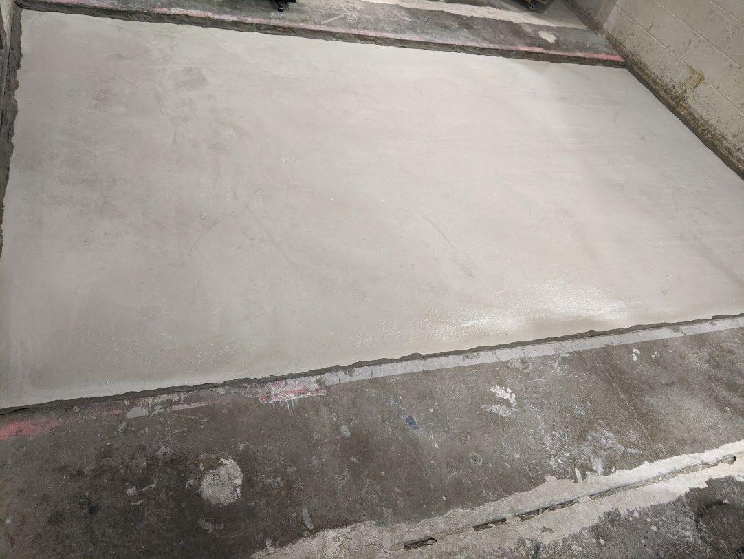
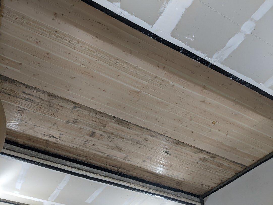
Page 6 of 17
University of Oregon
2024-07-08
Page 7 of 17
University of Oregon
2024-07-08 Page 8 of 17
University of Oregon
2024-07-08 Page 9 of 17
University of Oregon
2024-07-08 Page 10 of 17
University of Oregon
2024-07-08 Page 11 of 17
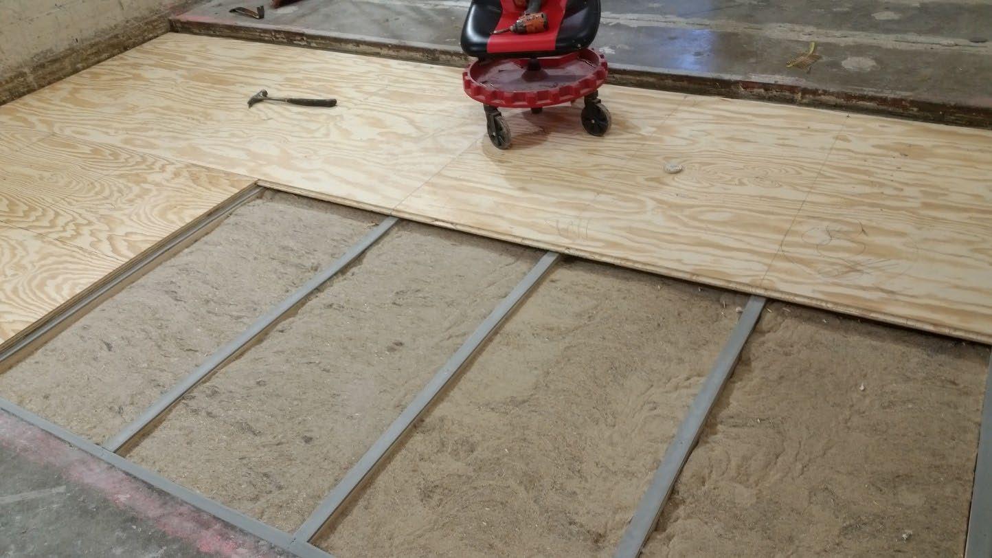

University of Oregon
2024-07-08 Page 12 of 17

University of Oregon
2024-07-08 Page 13 of 17
The averaged sound pressure levels, normalized to a receive room reference absorption of 10 m2, are tabulated at the sixteen frequency bands specified in ASTM E492-22 Section 9.5. A graphic presentation of the data and additional information appear on the following pages. The 95% confidence limit for the sound pressure level in the receive room is below the limits specified in ASTM E492-22 Section A1.4.
IIC=51
ABBREVIATION INDEX
FREQ. = 1/3 OCTAVE BAND CENTER FREQUENCY, Hz
Ln = NORMALIZED SOUND PRESSURE LEVEL, dB
ΔLn = 95% UNCERTAINTY LIMIT FOR Ln, dB
DEV. = DEVIATION FROM SHIFTED IIC CONTOUR, dB (SUM OF DEV = 26 ) IIC = IMPACT INSULATION CLASS
= LEVEL CORRECTED DUE TO BACKGROUND NOISE PER E492 SEC 10.2.2
LEVEL CORRECTED
Keith Kimberling Senior Experimentalist Test Engineer
Tested by______________________________ Report by__________________________
Approved by_______________________
Laboratory Manager
627 RIVERBANK DRIVE GENEVA, IL 60134 630-232-0104
University of Oregon
2024-07-08
Page 14 of 17
1” Maxxon gypcrete 2000 Multifamily, 1-1/8” T&G plywood subfloor screwed 24” OC with #9x3”, cavity filled with: HempWool Acoustibatt 3.5” hemp batt, 2x4 sleepers 24”OC with Rothoblaas Piano B acoustic strips stapled top/bottom, Vaagen Timbers 5-ply CLT 6.875” with plywood spline 3/4”x6” at the joint secured with #9x3” screws at 6” OC
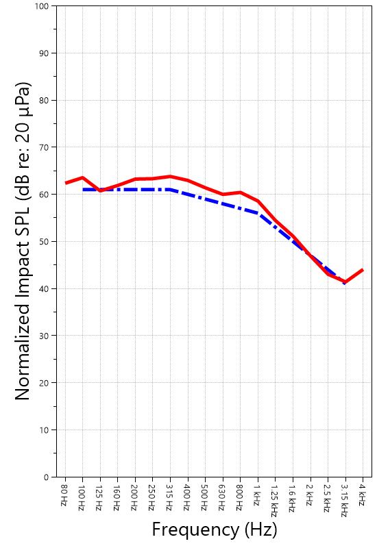
IMPACT SOUND PRESSURE LEVEL IMPACT INSULATION CLASS CONTOUR
627 RIVERBANK DRIVE GENEVA, IL 60134
630-232-0104
University of Oregon
2024-07-08
Page 15 of 17
Specimen: 1” Maxxon gypcrete 2000 Multifamily, 1-1/8” T&G plywood subfloor screwed 24” OC with #9x3”, cavity filled with: HempWool Acoustibatt 3.5” hemp batt, 2x4 sleepers 24”OC with Rothoblaas Piano B acoustic strips stapled top/bottom, Vaagen Timbers 5-ply CLT 6.875” with plywood spline 3/4”x6” at the joint secured with #9x3” screws at 6” OC (See Full Report)
The following non-accredited data were obtained in accordance with ASTM E492-22 but extend beyond the frequency range of 100 Hz to 3,150 Hz specified in Section 9.5. These unofficial results are representative of the RAL test environment only and intended for research & comparison purposes.
1/3 Octave Band
* Level corrected due to proximity to background noise per E492 Section 10.2.2
** Level corrected due to proximity to background noise per E492 Section 10.2.3, represents lower bound of specimen performance
627 RIVERBANK DRIVE GENEVA, IL 60134 630-232-0104
University of Oregon
2024-07-08
Page 16 of 17
Specimen: 1” Maxxon gypcrete 2000 Multifamily, 1-1/8” T&G plywood subfloor screwed 24” OC with #9x3”, cavity filled with: HempWool Acoustibatt 3.5” hemp batt, 2x4 sleepers 24”OC with Rothoblaas Piano B acoustic strips stapled top/bottom, Vaagen Timbers 5-ply CLT 6.875” with plywood spline 3/4”x6” at the joint secured with #9x3” screws at 6” OC (See Full Report)
ΔLn, the 95% confidence limit for the reported normalized sound pressure level, is calculated from the standard deviation of the set of sound pressure levels measured during this individual test. This metric is calculated in an effort to quantify the variability in measured levels due to the combined influences of varying sound pressure level in the receive room and changes in specimen response for different tapping machine locations.
Repeatability, expressed as a 95% confidence limit, is calculated from the standard deviation in normalized sound pressure level as obtained from a total of six consecutive tests conducted according to this test method by RAL from 2019-02-07 to 2019-02-12. The tests were performed on a specimen composed of 152.4 mm (6 in.) thick concrete slabs, which was left installed and unaltered between tests. This metric provides an estimate of the variation in results that might be observed if the test were repeated with no change to the installed specimen. Note that repeatability will vary with the construction type.
Specimen: 1” Maxxon gypcrete 2000 Multifamily, 1-1/8” T&G plywood subfloor screwed 24” OC with #9x3”, cavity filled with: HempWool Acoustibatt 3.5” hemp batt, 2x4 sleepers 24”OC with Rothoblaas Piano B acoustic strips stapled top/bottom, Vaagen Timbers 5-ply CLT 6.875” with plywood spline 3/4”x6” at the joint secured with #9x3” screws at 6” OC (See Full Report)
Current priorities in the architectural acoustics community involve the development of impact insulation metrics corresponding to impact sources of varying frequency content. Standard Classification ASTM E3222-20a provides a method for calculating the High-Frequency Impact Insulation Class (HIIC), using normalized impact sound pressure level (Ln) data at frequency bands from 400 Hz to 3150 Hz. Standard Classification ASTM E3207-21 provides a method for calculating the Low-Frequency Impact Insulation Class (LIIC) uses normalized impact sound pressure level (Ln) data at frequency bands from 50 Hz to 80 Hz.
Low-frequency impact noise correlates to the “thudding” of footfalls on lightweight structures, while highfrequency sound correlates to sources including the impacts of hard-heeled shoes, dragging furniture, dog toenails, and objects dropped on hard-surfaced flooring. When presented alongside the IIC rating, The LIIC and HIIC ratings can be used to predict how the nature of an impact source will affect the response of the floor-ceiling construction. A summary of impact insulation ratings, as calculated from the test results, is given below.
RIVERBANK DRIVE GENEVA, IL 60134 630-232-0104
University of Oregon RAL™-IN24-020 2024-07-08 Page 17 of 17
APPENDIX D: Instruments of Traceability
Specimen: 1” Maxxon gypcrete 2000 Multifamily, 1-1/8” T&G plywood subfloor screwed 24” OC with #9x3”, cavity filled with: HempWool Acoustibatt 3.5” hemp batt, 2x4 sleepers 24”OC with Rothoblaas Piano B acoustic strips stapled top/bottom, Vaagen Timbers 5-ply CLT 6.875” with plywood spline 3/4”x6” at the joint secured with #9x3” screws at 6” OC (See Full Report)
Description
System 2 Type 3160-A-042 3160106974 2023-08-11 2024-08-11
Bruel & Kjaer Mic And Preamp C Type 4943-B-001 2311439 2024-03-29 2025-03-29
Bruel & Kjaer Tapping Machine Type 3207 3151105 2023-12-14 2024-12-14
Bruel & Kjaer Pistonphone Type 4228 2781248 2023-07-12 2024-07-12
EXTECH Hygro 959 SD700 A.099959 2024-03-29 2025-03-29
EXTECH Hygro 639 SD700 A.103639 2023-12-01 2024-12-01
APPENDIX E: Revisions to Original Test Report
Specimen: 1” Maxxon gypcrete 2000 Multifamily, 1-1/8” T&G plywood subfloor screwed 24” OC with #9x3”, cavity filled with: HempWool Acoustibatt 3.5” hemp batt, 2x4 sleepers 24”OC with Rothoblaas Piano B acoustic strips stapled top/bottom, Vaagen Timbers 5-ply CLT 6.875” with plywood spline 3/4”x6” at the joint secured with #9x3” screws at 6” OC (See Full Report)
Date Revision
2024-07-31 Original report issued
2024-09-19 Page 17: Tapping machine added to instruments of traceability. -EPW END
627 RIVERBANK DRIVE GENEVA, IL 60134
630-232-0104
SPONSOR: University of Oregon Impact Sound Transmission Portland, OR RAL™-IN24-021
CONDUCTED: 2024-07-09 Page 1 of 19
ON: Marmoleum Decibel adhered with Sustain 1195, 1” Maxxon gypcrete 2000 Multifamily, 1-1/8” T&G plywood subfloor screwed 24” OC with #9x3”, cavity filled with: HempWool Acoustibatt 3.5” hemp batt, 2x4 sleepers 24”OC with Rothoblaas Piano B acoustic strips stapled top/bottom, Vaagen Timbers 5-ply CLT 6.875” with plywood spline 3/4”x6” at the joint secured with #9x3” screws at 6” OC
Riverbank Acoustical Laboratories™ is accredited by the U.S. Department of Commerce, National Institute of Standards and Technology (NIST) under the National Voluntary Laboratory Accreditation Program (NVLAP) as an ISO 17025:2017 Laboratory (NVLAP Lab Code: 100227-0) and for this test procedure. The test reported in this document conformed explicitly with ASTM E492-22: "Standard Test Method for Laboratory Measurement of Impact Sound Transmission Through Floor-Ceiling Assemblies Using the Tapping Machine." The single-number rating of the specimen was calculated according to ASTM E989-21: "Standard Classification for Determination of Single-Number Metrics for Impact Noise." A description of the measurement procedure and room specifications are available upon request. The results presented in this report apply to the individual test specimen as described and assembled.
The test specimen was designated by the sponsor as Marmoleum Decibel adhered with Sustain 1195, 1” Maxxon gypcrete 2000 Multifamily, 1-1/8” T&G plywood subfloor screwed 24” OC with #9x3”, cavity filled with: HempWool Acoustibatt 3.5” hemp batt, 2x4 sleepers 24”OC with Rothoblaas Piano B acoustic strips stapled top/bottom, Vaagen Timbers 5-ply CLT 6.875” with plywood spline 3/4”x6” at the joint secured with #9x3” screws at 6” OC. The following nominal product information was provided by the sponsor prior to testing. The accuracy of such sponsor-provided information can affect the validity of the test results.
Provided Description: Marmoleum Decibel adhered with Sustain 1195, 1” Maxxon gypcrete 2000 Multifamily, 1-1/8” T&G plywood subfloor screwed 24” OC with #9x3", cavity filled with: HempWool Acoustibatt 3.5” hemp batt, 2x4 sleepers 24”OC with Rothoblaas Piano B acoustic strips stapled top/bottom, Vaagen Timbers 5-ply CLT 6.875” with plywood spline 3/4”x6” at the joint secured with #9x3” screws at 6” OC
Manufacturer: University of Oregon
University of Oregon
2024-07-09
Page 2 of 19
The building contractor (Seth Priser) and RAL staff compiled a detailed construction specification as follows:
Cross-Laminated Timber (CLT)
Materials: 5-Ply Cross-Laminated Timber
Dimensions: 2 panels @ 1219 mm (48 in.) by 4229 mm (166.5 in.)
Thickness: 171 mm (6.75 in.)
Overall Weight: 953.45 kg (2102 lbs)
Mass Per Unit Volume: 539 kg/m3 (33.7 lbs/ft3)
Installation: CLT panels laid on 152 mm (6 in.) wide knee walls in test opening and butted to one another without sealant/adhesive.
3/4”x3” Rabbet on top side of one edge of each panel where they butt allowing a loose spline (below) to insert and join the two
Materials: 3/4” x 6” plywood spline
Dimensions: 1 piece @ 151 mm (5.9375 in.) wide by 2438 mm (96 in.) 1 piece @ 151 mm (5.9375 in.) wide by 1791 mm (70.5 in.)
Thickness: 19 mm (0.75 in.)
Overall Weight: 6.46 kg (14.25 lbs)
Mass Per Unit Length: 1.53 kg/m (1.03 lbs/ft)
Installation: Set in Rabbets of both CLT’s and screwed in place.
Fasteners: WSV Bugle head sub-floor screws, length @ 76 mm (3 in.)
Fastener Spacing: 6” o.c. on a line 3” from each edge of the spline (Centered on the rabbet of the CLT)
Piano B 40/40 (Lower Layer)
Manufacturer: Rothoblaas
Dimensions: 2 strips @ 40 mm (1.5625 in.) wide by 4267 mm (168 in.) long 8 strips @ 2362 mm (93 in.) wide by 40 mm (1.5625 in.) long
Thickness: 6.76 mm (0.266 in.)
Overall Weight: 4.59 kg (10.125 lbs)
Mass Per Unit Volume: 624 kg/m3 (40.0 lbs/ft3)
Installation: Fastened to underside of 2” x 4” wood sleepers with staples
Fasteners: Arrow staples, length @ 13 mm (0.5 in.)
University of Oregon
2024-07-09
SPECIMEN MEASUREMENTS & TEST CONDITIONS (continued)
2” by 4” SPF Framing Sleepers
Materials: Nominal 2”x 4” framing lumber
Page 3 of 19
Dimensions: 2 pieces @ 38 mm (1.5 in.) wide by 4255 mm (167.5 in.) long
8 pieces @ 2369 mm (93.25 in.) wide by 38 mm (1.5 in.) long
Depth: 89 mm (3.5 in.)
Overall Weight: 49.33 kg (108.75 lbs)
Mass Per Unit Length: 1.80 kg/m (1.21 lbs/ft)
Installation: Sleepers laid over CLT, resting on lower layer Piano B 40/40
Longer sleepers parallel to CLT like a rim joist
Shorter sleepers set like floor joists between rim joists
Shorter sleepers spaced approx. 610 mm (24 in.) on center
Shorter sleepers fastened to longer sleepers with screws, 2 screws per connection point
Fasteners: WSV Bugle head sub-floor screws, length @ 76 mm (3 in.)
Piano B 40/40 (Upper Layer)
Manufacturer: Rothoblaas
Dimensions: 2 strips @ 40 mm (1.5625 in.) wide by 4267 mm (168 in.) long 8 strips @ 2362 mm (93 in.) wide by 40 mm (1.5625 in.) long
Thickness: 6.76 mm (0.266 in.)
Overall Weight: 4.59 kg (10.125 lbs)
Mass Per Unit Volume: 624 kg/m3 (40.0 lbs/ft3)
Installation: Fastened to top of 2” x 4” wood sleepers with staples
Fasteners: Arrow staples, length @ 13 mm (0.5 in.)
Hemp Board
Materials: 3” Hemp fiber board
Manufacturer: Hempitecture
Dimensions: 7 pieces @ 572 mm (22.5 in.) wide by 2369 mm (93.25 in.) long
Depth: 76 mm (3 in.)
Overall Weight: 37.53 kg (82.75 lbs)
Mass Per Unit Volume: 52.0 kg/m3 (3.25 lbs/ft3)
Installation: Friction fit between sleepers and on top of CLT
University of Oregon
2024-07-09
SPECIMEN MEASUREMENTS & TEST CONDITIONS (continued)
Plywood Subfloor
Materials: T&G Plywood
Dimensions: 1 piece @ 1219 mm (48 in.) wide by 1829 mm (72 in.)
1 piece @ 1219 mm (48 in.) wide by 2438 mm (96 in.)
1 piece @ 1219 mm (48 in.) wide by 1822 mm (71.75 in.)
1 piece @ 1219 mm (48 in.) wide by 2432 mm (95.75 in.)
Thickness: 29 mm (1.125 in.)
Overall Weight: 173.5 kg (382.5 lbs)
Mass Per Unit Volume: 584 kg/m3 (36.5 lbs/ft3)
Installation: Placed over upper layer Piano B 40/40 over sleepers
Fastened to sleepers through Piano B 40/40 with screws
Plywood piece joints staggered
Fasteners: WSV Bugle head sub-floor screws, length @ 76 mm (3 in.)
Fastener Spacing: 610 mm (24 in.) on center
Gypcrete
Page 4 of 19
Materials: Gypcrete mix
Manufacturer: Maxxon
Dimensions: 2438 mm (96 in.) by 4267 mm (168 in.) as installed
Thickness: Approx 25 mm (1 in.)
Mix Ratio: 2.5 gallons water / 40 lbs gypcrete / 75 lbs all-purpose sand
Overall Dry Weight: 469.47 kg (1035 lbs)
Mass Per Unit Volume: 1780 kg/m3 (111 lbs/ft3)
Installation: Poured over plywood subfloor
Gauge rake was used to level product to 1” of thickness
Wet gypcrete mix was poured on (2024-07-01, approx. 3:40 PM)
University of Oregon
2024-07-09
SPECIMEN MEASUREMENTS & TEST CONDITIONS (continued)
Adhesive
Materials: Sustain 1195 Sheet and Tile adhesive
Manufacturer: Forbo
Dimensions: Approx. 2438 mm (96 in.) by 4267 mm (168 in.) as installed
Overall Weight: 2.95 kg (6.5 lbs)
Mass Per Unit Area: 0.28 kg/m2 (0.06 lbs/ft2)
Flooring
Page 5 of 19
Installation: Troweled directly to gypcrete with a 1/16x1/16x1/16 square notch trowel
Once troweled, adhesive was left “open” for 15 min to allow it to “tack” before flooring was installed.
Materials: Marmoleum Decibel
Manufacturer: Forbo
Dimensions: 2 pieces @ 2007 mm (79 in.) by 2464 mm (97 in.) 1 piece @ 260 mm (10.25 in.) by 2464 mm (97 in.)
Thickness: 6 mm (0.25 in.)
Overall Weight: 35.38 kg (78 lbs)
Mass Per Unit Volume: 529 kg/m3 (33.0 lbs/ft3)
Installation: Two (2) 79” segments perpendicular to Plywood 10” strip to complete Joints staggered from parallel plywood joints by + 6” Rolled with 100lb roller in each direction
University of Oregon RAL™-IN24-021 2024-07-09 Page 6 of 19
SPECIMEN MEASUREMENTS & TEST CONDITIONS (continued)
Overall Specimen Measurements
Dimensions: 2.44 m (96.0 in) wide by 3.86 m (152.0 in) long
Thickness: 0.33 m (13.125 in)
Weight: 1734.31 kg (3823.5 lbs)
Overall Area: 9.414 m² (101.33 ft²)
Mass per Unit Area: 166.68 kg/m² (34.14 lbs/ft²)
Test Aperture
Opening Size: 4.27 m (14.0 ft.) by 6.10 m (20 ft.)
Filler Wall: Yes
Aperture Size: 2.44 m (96.0 in) wide by 3.86 m (152.0 in) long
Transmission Area: 9.414 m² (101.33 ft²)
Sealed: Entire periphery (both sides) with dense mastic
Test Environment
Source Room
Volume: 130.9 m³
Temperature: 22.2 °C ± 0.0 °C
Relative Humidity: 62.0 % ± 2.0 %
Receive Room
Volume: 81.44 m³
Temperature: 21.7 °C ± 0.0 °C
Relative Humidity: 64.0 % ± 0.0 %
Requirements
Temperature: 22º C +/- 5° C, not more than 3° C change over all tests.
Relative Humidity: ≥ 30% RH; not more than +/- 3% change over all tests.
University of Oregon
2024-07-09 Page 7 of 19
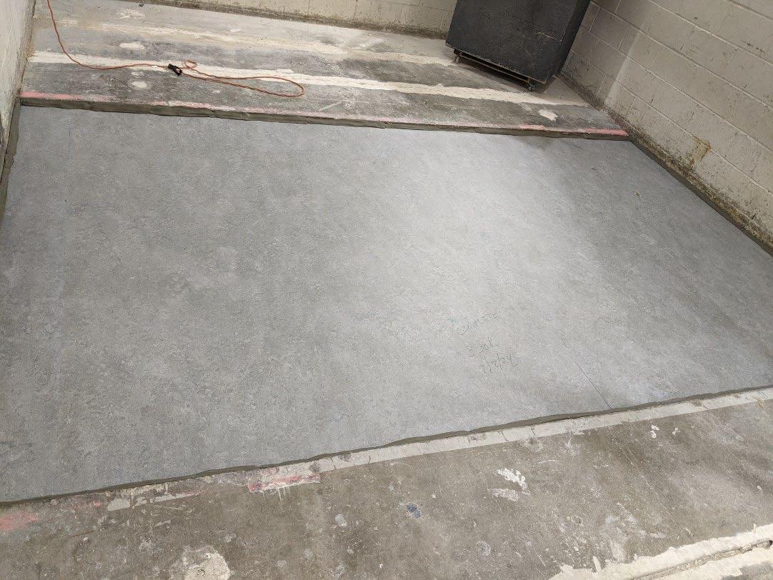
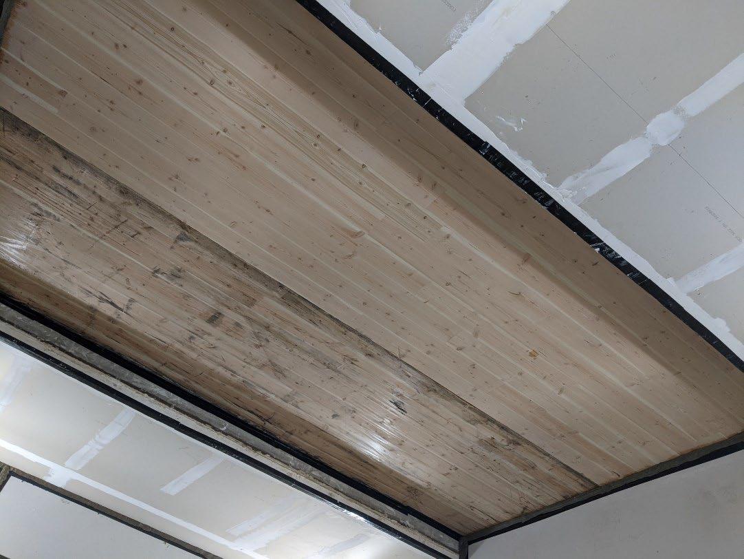
University of Oregon
2024-07-09 Page 8 of 19
University of Oregon
2024-07-09
Page 9 of 19
University of Oregon
2024-07-09 Page 10 of 19
University of Oregon
2024-07-09 Page 11 of 19
University of Oregon
2024-07-09 Page 12 of 19
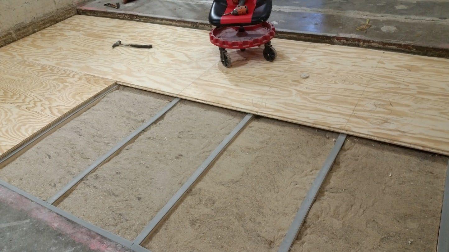
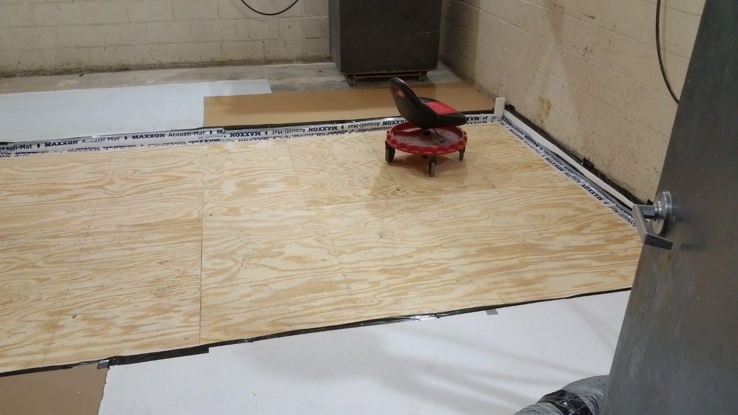
University of Oregon
2024-07-09 Page 13 of 19
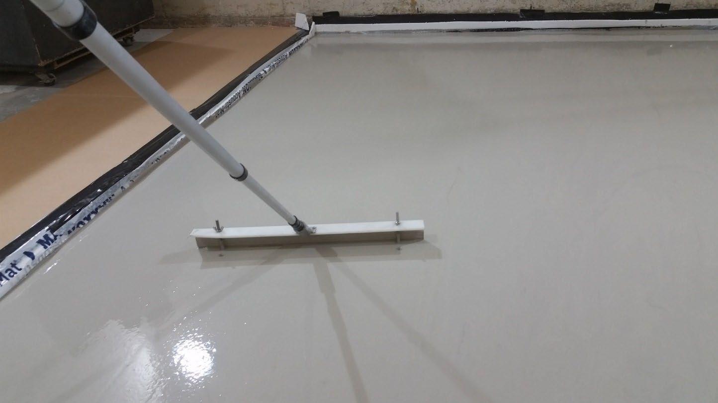
University of Oregon
2024-07-09 Page 14 of 19
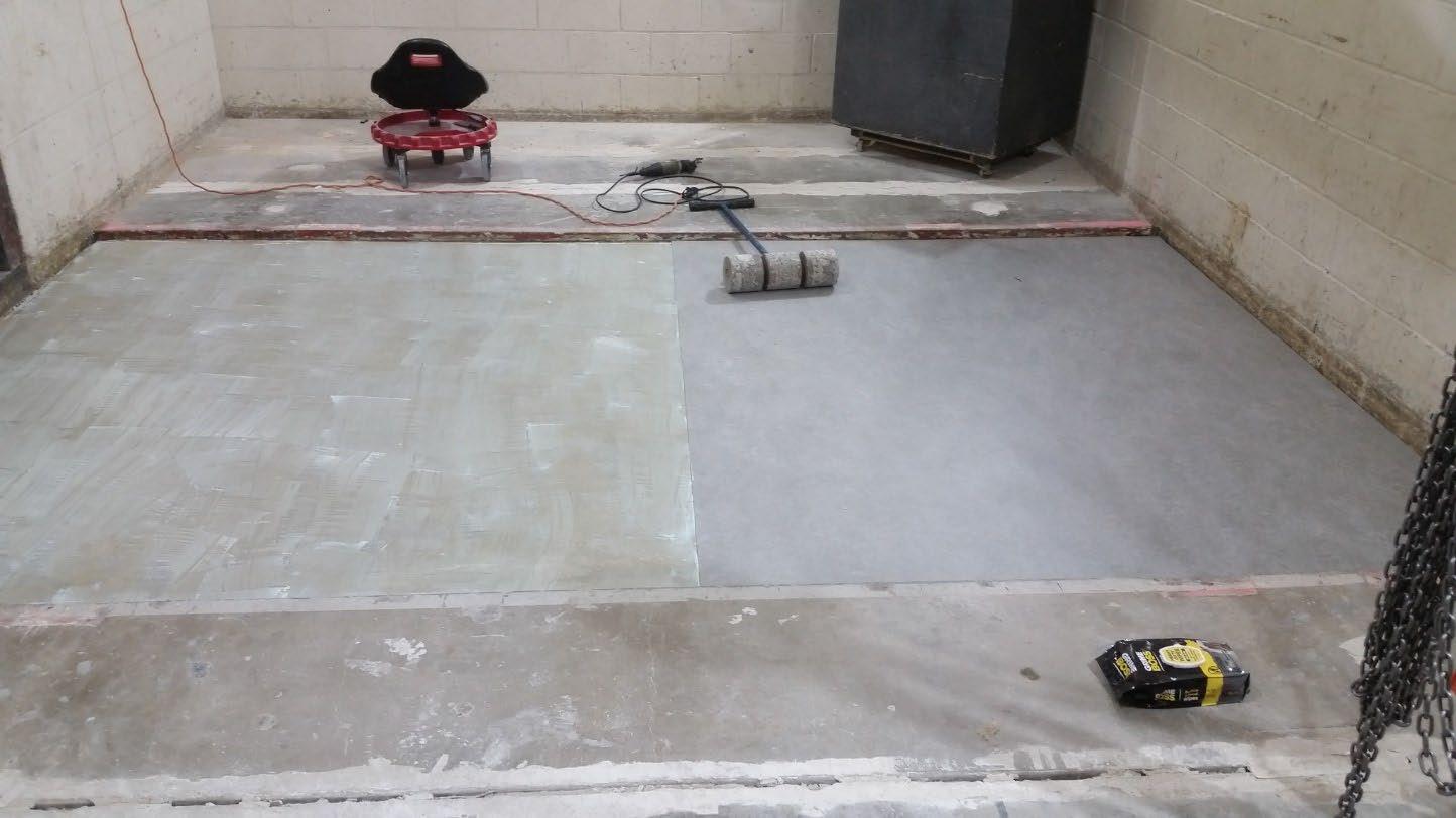
University of Oregon
2024-07-09 Page 15 of 19
The averaged sound pressure levels, normalized to a receive room reference absorption of 10 m2, are tabulated at the sixteen frequency bands specified in ASTM E492-22 Section 9.5. A graphic presentation of the data and additional information appear on the following pages. The 95% confidence limit for the sound pressure level in the receive room is below the limits specified in ASTM E492-22 Section A1.4.
ABBREVIATION INDEX
FREQ. = 1/3 OCTAVE BAND CENTER FREQUENCY, Hz
Ln = NORMALIZED SOUND PRESSURE LEVEL, dB
ΔLn = 95% UNCERTAINTY LIMIT FOR Ln, dB
DEV. = DEVIATION FROM SHIFTED IIC CONTOUR, dB (SUM OF DEV = 28 ) IIC = IMPACT INSULATION CLASS
LEVEL
Keith Kimberling Senior Experimentalist Test Engineer
Tested by______________________________ Report by__________________________
Approved by_______________________
Laboratory Manager
627 RIVERBANK DRIVE GENEVA, IL 60134 630-232-0104
University of Oregon
2024-07-09
Page 16 of 19
Marmoleum Decibel adhered with Sustain 1195, 1” Maxxon gypcrete 2000 Multifamily, 1-1/8” T&G plywood subfloor screwed 24” OC with #9x3”, cavity filled with: HempWool Acoustibatt 3.5” hemp batt, 2x4 sleepers 24”OC with Rothoblaas Piano B acoustic strips stapled top/bottom, Vaagen Timbers 5-ply CLT 6.875” with plywood spline 3/4”x6” at the joint secured with #9x3” screws at 6” OC
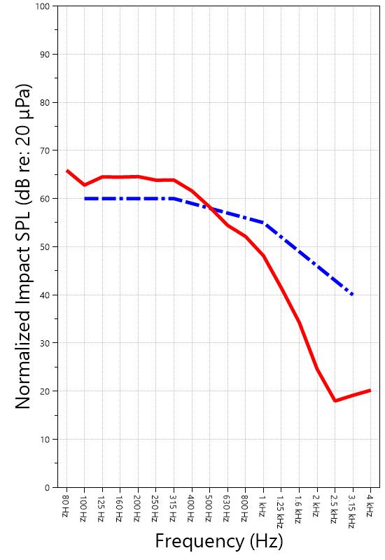
627 RIVERBANK DRIVE GENEVA, IL 60134 630-232-0104
University of Oregon
2024-07-09
Page 17 of 19
Specimen: Marmoleum Decibel adhered with Sustain 1195, 1” Maxxon gypcrete 2000 Multifamily, 1-1/8” T&G plywood subfloor screwed 24” OC with #9x3”, cavity filled with: HempWool Acoustibatt 3.5” hemp batt, 2x4 sleepers 24”OC with Rothoblaas Piano B acoustic strips stapled top/bottom, Vaagen Timbers 5-ply CLT 6.875” with plywood spline 3/4”x6” at the joint secured with #9x3” screws at 6” OC (See Full Report) The following non-accredited data were obtained in accordance with ASTM E492-22 but extend beyond the frequency range of 100 Hz to 3,150 Hz specified in Section 9.5. These unofficial results are representative of the RAL test environment only and intended for research & comparison purposes.
1/3 Octave Band
* Level corrected due to proximity to background noise per E492 Section 10.2.2
** Level corrected due to proximity to background noise per E492 Section 10.2.3, represents lower bound of specimen performance
WALLACE CLEMENT SABINE 627 RIVERBANK DRIVE GENEVA, IL 60134 630-232-0104
University of Oregon RAL™-IN24-021 2024-07-09
Page 18 of 19
Specimen: Marmoleum Decibel adhered with Sustain 1195, 1” Maxxon gypcrete 2000 Multifamily, 1-1/8” T&G plywood subfloor screwed 24” OC with #9x3”, cavity filled with: HempWool Acoustibatt 3.5” hemp batt, 2x4 sleepers 24”OC with Rothoblaas Piano B acoustic strips stapled top/bottom, Vaagen Timbers 5-ply CLT 6.875” with plywood spline 3/4”x6” at the joint secured with #9x3” screws at 6” OC (See Full Report)
ΔLn, the 95% confidence limit for the reported normalized sound pressure level, is calculated from the standard deviation of the set of sound pressure levels measured during this individual test. This metric is calculated in an effort to quantify the variability in measured levels due to the combined influences of varying sound pressure level in the receive room and changes in specimen response for different tapping machine locations.
Repeatability, expressed as a 95% confidence limit, is calculated from the standard deviation in normalized sound pressure level as obtained from a total of six consecutive tests conducted according to this test method by RAL from 2019-02-07 to 2019-02-12. The tests were performed on a specimen composed of 152.4 mm (6 in.) thick concrete slabs, which was left installed and unaltered between tests. This metric provides an estimate of the variation in results that might be observed if the test were repeated with no change to the installed specimen. Note that repeatability will vary with the construction type.
Specimen: Marmoleum Decibel adhered with Sustain 1195, 1” Maxxon gypcrete 2000 Multifamily, 1-1/8” T&G plywood subfloor screwed 24” OC with #9x3”, cavity filled with: HempWool Acoustibatt 3.5” hemp batt, 2x4 sleepers 24”OC with Rothoblaas Piano B acoustic strips stapled top/bottom, Vaagen Timbers 5-ply CLT 6.875” with plywood spline 3/4”x6” at the joint secured with #9x3” screws at 6” OC (See Full Report)
Current priorities in the architectural acoustics community involve the development of impact insulation metrics corresponding to impact sources of varying frequency content. Standard Classification ASTM E3222-20a provides a method for calculating the High-Frequency Impact Insulation Class (HIIC), using normalized impact sound pressure level (Ln) data at frequency bands from 400 Hz to 3150 Hz. Standard Classification ASTM E3207-21 provides a method for calculating the Low-Frequency Impact Insulation Class (LIIC) uses normalized impact sound pressure level (Ln) data at frequency bands from 50 Hz to 80 Hz.
Low-frequency impact noise correlates to the “thudding” of footfalls on lightweight structures, while highfrequency sound correlates to sources including the impacts of hard-heeled shoes, dragging furniture, dog toenails, and objects dropped on hard-surfaced flooring. When presented alongside the IIC rating, The LIIC and HIIC ratings can be used to predict how the nature of an impact source will affect the response of the floor-ceiling construction. A summary of impact insulation ratings, as calculated from the test results, is given below.
627 RIVERBANK DRIVE GENEVA, IL 60134 630-232-0104
University of Oregon RAL™-IN24-021 2024-07-09 Page 19 of 19
APPENDIX D: Instruments of Traceability
Specimen: Marmoleum Decibel adhered with Sustain 1195, 1” Maxxon gypcrete 2000 Multifamily, 1-1/8” T&G plywood subfloor screwed 24” OC with #9x3”, cavity filled with: HempWool Acoustibatt 3.5” hemp batt, 2x4 sleepers 24”OC with Rothoblaas Piano B acoustic strips stapled top/bottom, Vaagen Timbers 5-ply CLT 6.875” with plywood spline 3/4”x6” at the joint secured with #9x3” screws at 6” OC (See Full Report)
Description
System 2 Type 3160-A-042 3160106974 2023-08-11 2024-08-11
Bruel & Kjaer Mic And Preamp C Type 4943-B-001 2311439 2024-03-29 2025-03-29
Bruel & Kjaer Tapping Machine Type 3207 3151105 2023-12-14 2024-12-14
Bruel & Kjaer Pistonphone Type 4228 2781248 2023-07-12 2024-07-12
EXTECH Hygro 959 SD700 A.099959 2024-03-29 2025-03-29
EXTECH Hygro 639 SD700 A.103639 2023-12-01 2024-12-01
APPENDIX E: Revisions to Original Test Report
Specimen: Marmoleum Decibel adhered with Sustain 1195, 1” Maxxon gypcrete 2000 Multifamily, 11/8” T&G plywood subfloor screwed 24” OC with #9x3”, cavity filled with: HempWool
Acoustibatt 3.5” hemp batt, 2x4 sleepers 24”OC with Rothoblaas Piano B acoustic strips stapled top/bottom, Vaagen Timbers 5-ply CLT 6.875” with plywood spline 3/4”x6” at the joint secured with #9x3” screws at 6” OC (See Full Report)
Date Revision
2024-07-31 Original report issued
2024-09-19 Page 19: Tapping machine added to instruments of traceability. -EPW
627 RIVERBANK DRIVE
GENEVA, IL 60134
630-232-0104
SPONSOR: University of Oregon Impact Sound Transmission Portland, OR RAL™-IN24-022
CONDUCTED: 2024-07-22
Page 1 of 15
Riverbank Acoustical Laboratories™ is accredited by the U.S. Department of Commerce, National Institute of Standards and Technology (NIST) under the National Voluntary Laboratory Accreditation Program (NVLAP) as an ISO 17025:2017 Laboratory (NVLAP Lab Code: 100227-0) and for this test procedure. The test reported in this document conformed explicitly with ASTM E492-22: "Standard Test Method for Laboratory Measurement of Impact Sound Transmission Through Floor-Ceiling Assemblies Using the Tapping Machine." The single-number rating of the specimen was calculated according to ASTM E989-21: "Standard Classification for Determination of Single-Number Metrics for Impact Noise." A description of the measurement procedure and room specifications are available upon request. The results presented in this report apply to the individual test specimen as described and assembled.
The test specimen was designated by the sponsor as 1” Maxxon gypcrete 2000 Multifamily, Certainteed MemBrain vapor retarder, 3” of 3/8” limestone chip, Hempitecture 2” hemp fiber board, Vaagen Timbers 5-ply CLT 6.875” with plywood spline 3/4”x6” at the joint secured with #9x3” screws at 6” OC. The following nominal product information was provided by the sponsor prior to testing. The accuracy of such sponsor-provided information can affect the validity of the test results.
Provided Description: 1” Maxxon gypcrete 2000 Multifamily, Certainteed MemBrain vapor retarder, 3” of 3/8" limestone chip, Hempitecture 2” hemp fiber board, Vaagen Timbers 5-ply CLT 6.875” with plywood spline 3/4”x6” at the joint secured with #9x3” screws at 6” OC Manufacturer: University of Oregon
ON: 1” Maxxon gypcrete 2000 Multifamily, Certainteed MemBrain vapor retarder, 3” of 3/8” limestone chip, Hempitecture 2” hemp fiber board, Vaagen Timbers 5-ply CLT 6.875” with plywood spline 3/4”x6” at the joint secured with #9x3” screws at 6” OC RIVERBANK ACOUSTICAL LABORATORIES IS ACCREDITED BY NVLAP (LAB CODE 100227-0) FOR ACOUSTICAL TESTING SERVICES IN ACCORDANCE WITH ISO/IEC 17025:2017 AND FOR THIS PROCEDURE. THIS REPORT MUST NOT BE USED BY THE CLIENT TO CLAIM PRODUCT CERTIFICATION, APPROVAL, OR ENDORSEMENT BY RAL, NVLAP, NIST, OR ANY AGENCY OF THE U.S. GOVERNMENT. THIS REPORT SHALL NOT BE MODIFIED WITHOUT THE WRITTEN APPROVAL OF RAL. THE RESULTS REPORTED APPLY ONLY TO THE SPECIFIC SAMPLE SUBMITTED FOR TESTING; RAL ASSUMES NO RESPONSIBILITY FOR THE PERFORMANCE OF ANY OTHER SAMPLE
University of Oregon
2024-07-22
Page 2 of 15
The building contractor (Seth Priser) and RAL staff compiled a detailed construction specification as follows:
Cross-Laminated Timber (CLT)
Materials: 5-Ply Cross-Laminated Timber
Dimensions: 2 panels @ 1219 mm (48 in.) by 4229 mm (166.5 in.)
Thickness: 171 mm (6.75 in.)
Overall Weight: 953.45 kg (2102 lbs)
Mass Per Unit Volume: 539 kg/m3 (33.7 lbs/ft3)
Installation: CLT panels laid on 152 mm (6 in.) wide knee walls in test opening and butted to one another without sealant/adhesive.
3/4”x3” Rabbet on top side of one edge of each panel where they butt allowing a loose spline (below) to insert and join the two
Materials: 3/4” x 6” plywood spline
Dimensions: 1 piece @ 151 mm (5.9375 in.) wide by 2438 mm (96 in.) 1 piece @ 151 mm (5.9375 in.) wide by 1791 mm (70.5 in.)
Thickness: 19 mm (0.75 in.)
Overall Weight: 6.46 kg (14.25 lbs)
Mass Per Unit Length: 1.53 kg/m (1.03 lbs/ft)
Installation: Set in Rabbets of both CLT’s and screwed in place.
Fasteners: WSV Bugle head sub-floor screws, length @ 76 mm (3 in.)
Fastener Spacing: 6” o.c. on a line 3” from each edge of the spline (Centered on the rabbet of the CLT)
Materials: 2” Hemp fiber board
Manufacturer: Hempitecture
Dimensions: 3 pieces @ 1216 mm (47.875 in.) wide by 2448 mm (96.375 in.) long 1 piece @ 613 mm (24.125 in.) wide by 2448 mm (96.375 in.) long
Depth: 51 mm (2 in.)
Overall Weight: 69.51 kg (153.25 lbs)
Mass Per Unit Volume: 131 kg/m3 (8.19 lbs/ft3)
Installation: Loose laid directly on top of CLT Perpendicular to CLT
627 RIVERBANK DRIVE GENEVA, IL 60134 630-232-0104
University of Oregon
2024-07-22
SPECIMEN MEASUREMENTS & TEST CONDITIONS (continued)
Crushed Limestone
Materials: CA-16 3/8” chip crushed limestone
Page 3 of 15
Dimensions: 2438 mm (96 in.) wide by 4267 mm (168 in.) long, as installed
Depth: 76 mm (3 in.)
Overall Weight: 1224.02 kg (2698.5 lbs)
Installation: Loose laid on top of the Hemp fiberboard ½” polystyrene used as an isolation around the perimeter
Vapor Barrier
Materials: Membrain Vapor barrier
Manufacturer: Saint Gobain
Dimensions: Approx. 2438 mm (96 in.) by 4267 mm (168 in.) as installed
Overall Weight: 0.79 kg (1.75 lbs)
Mass Per Unit Area: 0.08 kg/m2 (0.02 lbs/ft2)
Installation: Loose laid over crushed limestone
Gypcrete
Materials: Gypcrete mix
Manufacturer: Maxxon
Dimensions: 2438 mm (96 in.) by 4267 mm (168 in.) as installed
Thickness: 25 mm (1 in.)
Mix Ratio: 2.5 gallons water / 40 lbs gypcrete / 75 lbs all-purpose sand
Overall Dry Weight: 521.63 kg (1150 lbs)
Mass Per Unit Volume: 1970 kg/m3 (123 lbs/ft3)
Installation: Poured over vapor barrier
A screed was used to spread the wet gypcrete mix
Wet gypcrete mix was poured on (2024-07-10, approx. 4:30 PM)
University of Oregon
2024-07-22 Page 4 of 15
SPECIMEN MEASUREMENTS & TEST CONDITIONS (continued)
Overall Specimen Measurements
Dimensions: 2.44 m (96.0 in) wide by 3.86 m (152.0 in) long
Thickness: 0.32 m (12.75 in)
Weight: 2775.87 kg (6119.75 lbs)
Overall Area: 9.414 m² (101.33 ft²)
Mass per Unit Area: 266.78 kg/m² (54.64 lbs/ft²)
Test Aperture
Opening Size: 4.27 m (14.0 ft.) by 6.10 m (20 ft.)
Filler Wall: Yes
Aperture Size: 2.44 m (96.0 in) wide by 3.86 m (152.0 in) long
Transmission Area: 9.414 m² (101.33 ft²)
Sealed: Entire periphery (both sides) with dense mastic
Test Environment
Source Room
Volume: 130.9 m³
Temperature: 23.3 °C ± 0.0 °C
Relative Humidity: 67.5 % ± 1.0 %
Receive Room
Volume: 81.44 m³
Temperature: 22.2 °C ± 0.0 °C
Relative Humidity: 67.0 % ± 0.0 %
Requirements
Temperature: 22º C +/- 5° C, not more than 3° C change over all tests.
Relative Humidity: ≥ 30% RH; not more than +/- 3% change over all tests.
University of Oregon
2024-07-22
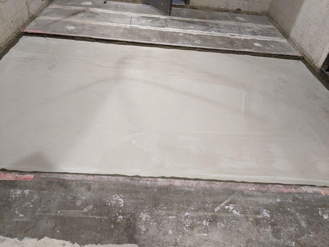
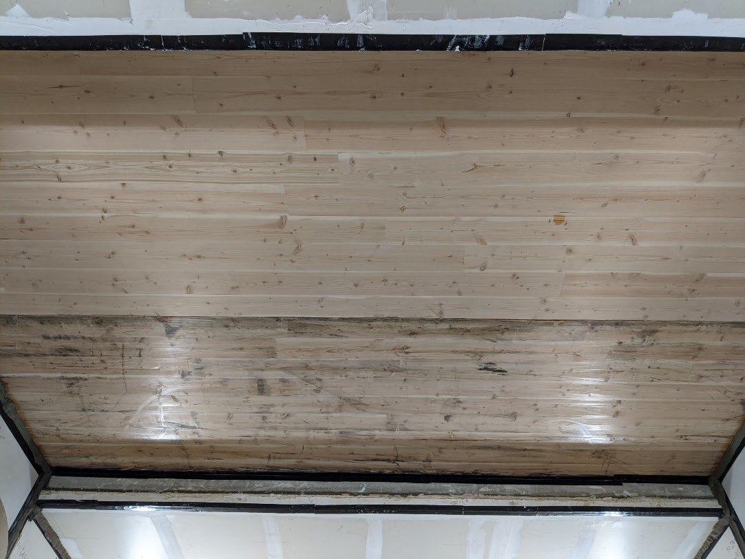
Page 5 of 15
University of Oregon
2024-07-22 Page 6 of 15
University of Oregon
2024-07-22
Page 7 of 15
University of Oregon
2024-07-22 Page 8 of 15
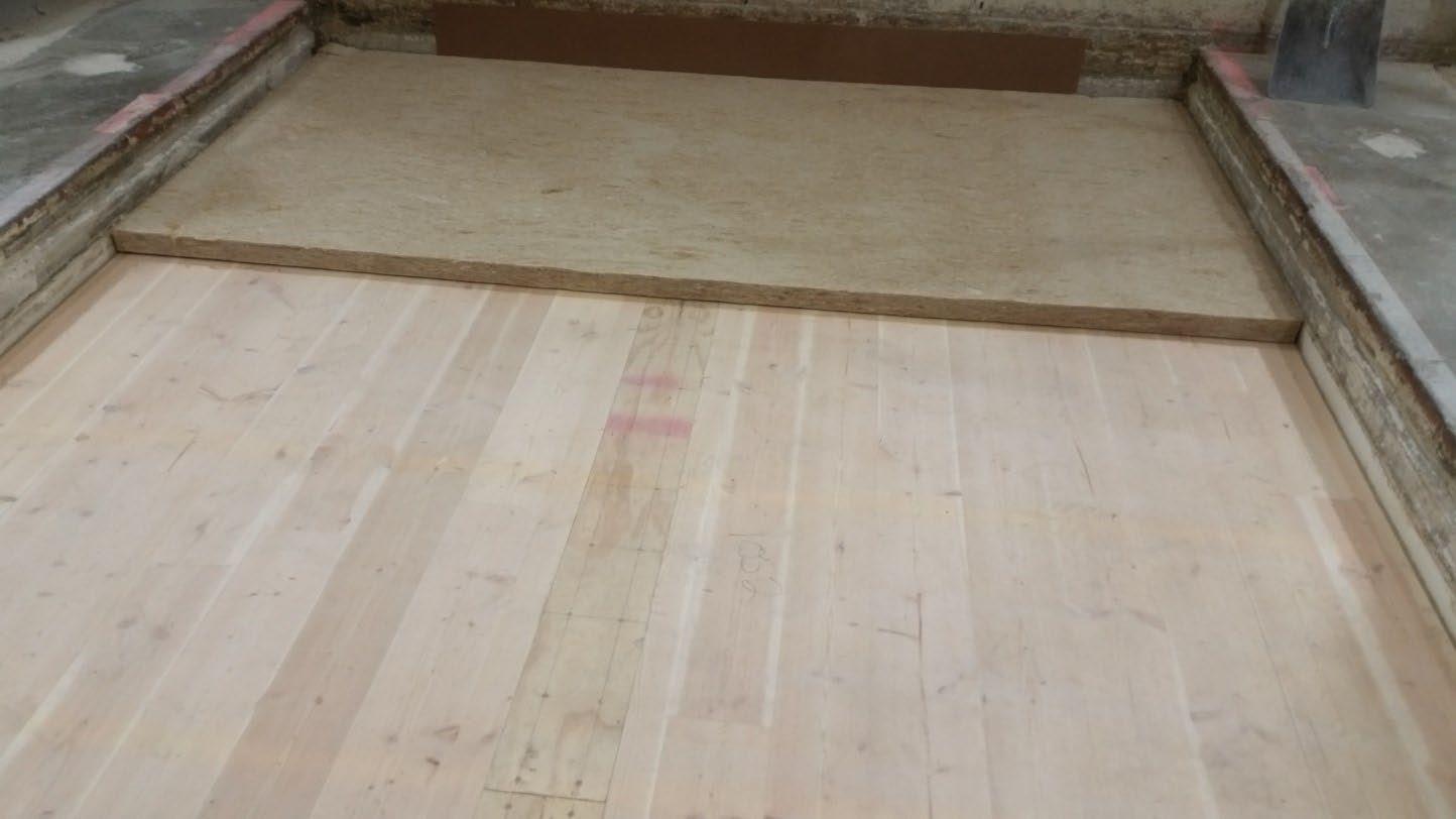
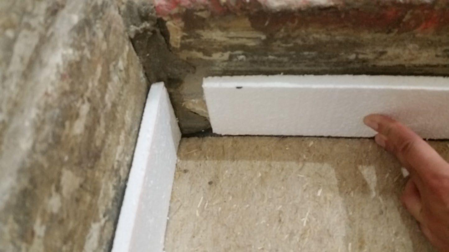
University of Oregon
2024-07-22 Page 9 of 15
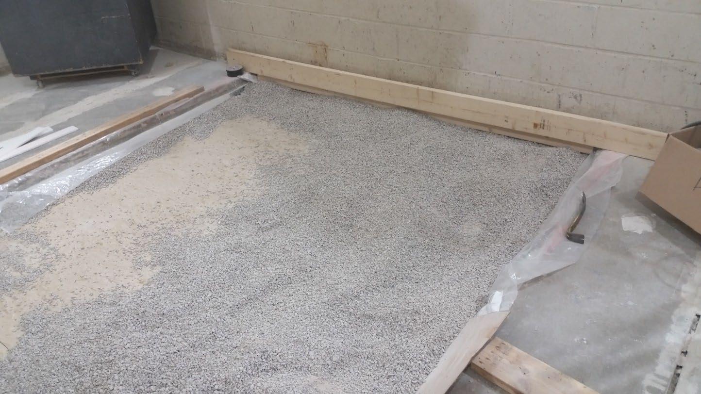
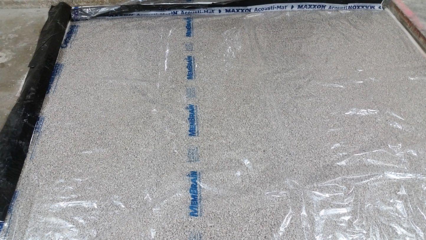
University of Oregon
2024-07-22 Page 10 of 15
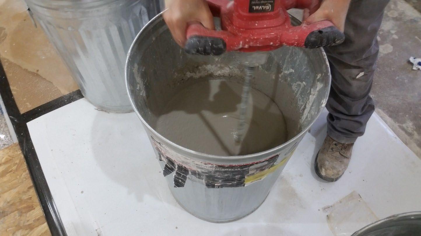
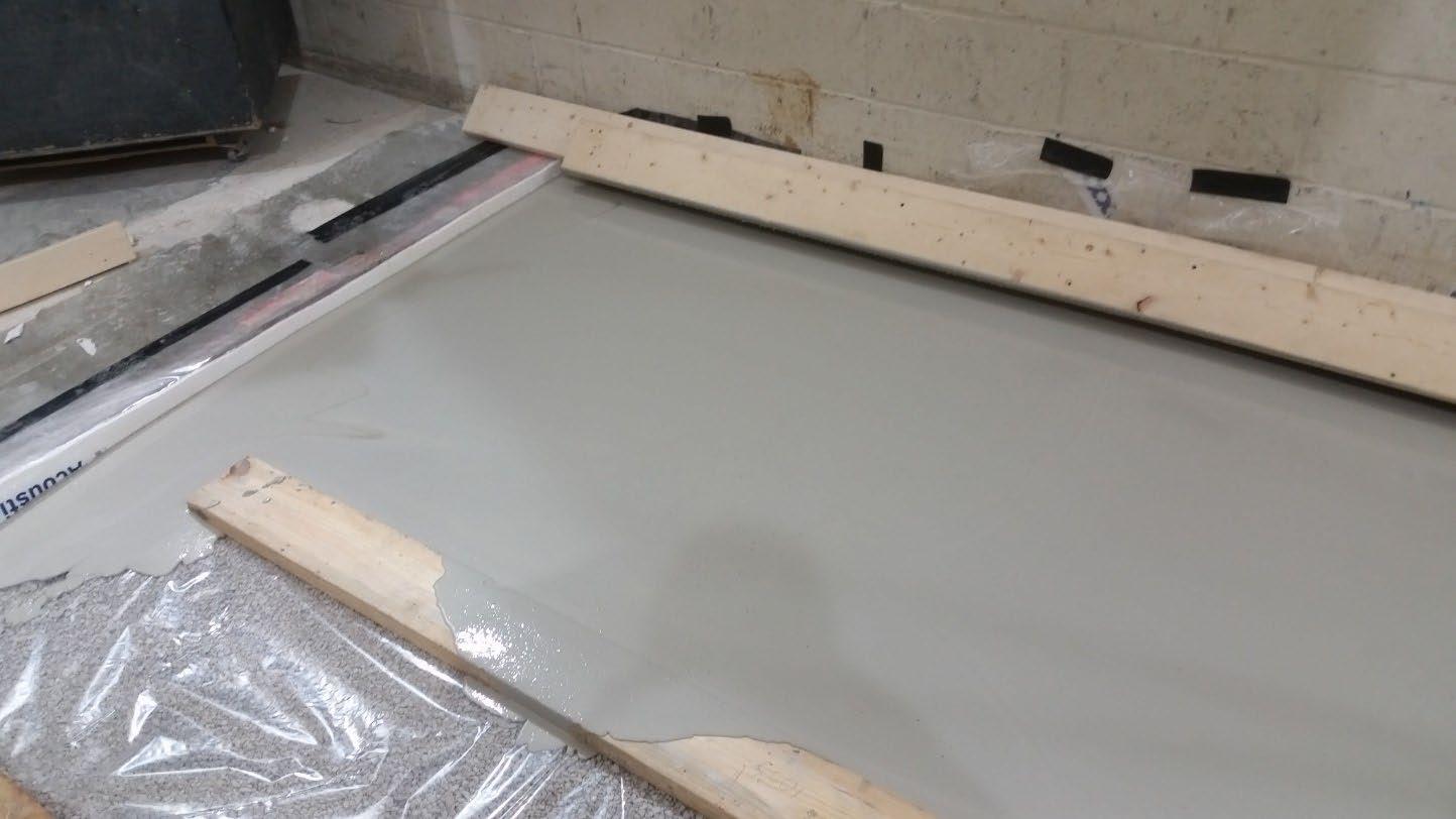
University of Oregon
2024-07-22
Page 11 of 15
The averaged sound pressure levels, normalized to a receive room reference absorption of 10 m2, are tabulated at the sixteen frequency bands specified in ASTM E492-22 Section 9.5. A graphic presentation of the data and additional information appear on the following pages. The 95% confidence limit for the sound pressure level in the receive room is below the limits specified in ASTM E492-22 Section A1.4.
IIC=50
ABBREVIATION INDEX
FREQ. = 1/3 OCTAVE BAND CENTER FREQUENCY, Hz
Ln = NORMALIZED SOUND PRESSURE LEVEL, dB
ΔLn = 95% UNCERTAINTY LIMIT FOR Ln, dB
DEV. = DEVIATION FROM SHIFTED IIC CONTOUR, dB (SUM OF DEV = 16 ) IIC = IMPACT INSULATION CLASS
LEVEL
Keith Kimberling
Keith Kimberling Test Engineer Test Engineer
Tested by______________________________ Report by__________________________
Approved by_______________________
Laboratory Manager
627 RIVERBANK DRIVE GENEVA, IL 60134 630-232-0104
University of Oregon
2024-07-22
Page 12 of 15
1” Maxxon gypcrete 2000 Multifamily, Certainteed MemBrain vapor retarder, 3” of 3/8” limestone chip, Hempitecture 2” hemp fiber board, Vaagen Timbers 5-ply CLT 6.875” with plywood spline 3/4”x6” at the joint secured with #9x3” screws at 6” OC
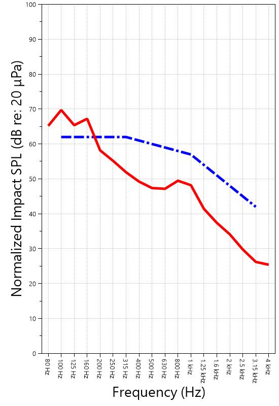
627 RIVERBANK DRIVE GENEVA, IL 60134 630-232-0104
University of Oregon
2024-07-22
Page 13 of 15
Specimen: 1” Maxxon gypcrete 2000 Multifamily, Certainteed MemBrain vapor retarder, 3” of 3/8” limestone chip, Hempitecture 2” hemp fiber board, Vaagen Timbers 5-ply CLT 6.875” with plywood spline 3/4”x6” at the joint secured with #9x3” screws at 6” OC (See Full Report)
The following non-accredited data were obtained in accordance with ASTM E492-22 but extend beyond the frequency range of 100 Hz to 3,150 Hz specified in Section 9.5. These unofficial results are representative of the RAL test environment only and intended for research & comparison purposes.
1/3 Octave Band
* Level corrected due to proximity to background noise per E492 Section 10.2.2
** Level corrected due to proximity to background noise per E492 Section 10.2.3, represents lower bound of specimen performance
627 RIVERBANK DRIVE GENEVA, IL 60134 630-232-0104
University of Oregon
2024-07-22
Page 14 of 15
Specimen: 1” Maxxon gypcrete 2000 Multifamily, Certainteed MemBrain vapor retarder, 3” of 3/8” limestone chip, Hempitecture 2” hemp fiber board, Vaagen Timbers 5-ply CLT 6.875” with plywood spline 3/4”x6” at the joint secured with #9x3” screws at 6” OC (See Full Report)
ΔLn, the 95% confidence limit for the reported normalized sound pressure level, is calculated from the standard deviation of the set of sound pressure levels measured during this individual test. This metric is calculated in an effort to quantify the variability in measured levels due to the combined influences of varying sound pressure level in the receive room and changes in specimen response for different tapping machine locations.
Repeatability, expressed as a 95% confidence limit, is calculated from the standard deviation in normalized sound pressure level as obtained from a total of six consecutive tests conducted according to this test method by RAL from 2019-02-07 to 2019-02-12. The tests were performed on a specimen composed of 152.4 mm (6 in.) thick concrete slabs, which was left installed and unaltered between tests. This metric provides an estimate of the variation in results that might be observed if the test were repeated with no change to the installed specimen. Note that repeatability will vary with the construction type.
Specimen: 1” Maxxon gypcrete 2000 Multifamily, Certainteed MemBrain vapor retarder, 3” of 3/8” limestone chip, Hempitecture 2” hemp fiber board, Vaagen Timbers 5-ply CLT 6.875” with plywood spline 3/4”x6” at the joint secured with #9x3” screws at 6” OC (See Full Report)
Current priorities in the architectural acoustics community involve the development of impact insulation metrics corresponding to impact sources of varying frequency content. Standard Classification ASTM E3222-20a provides a method for calculating the High-Frequency Impact Insulation Class (HIIC), using normalized impact sound pressure level (Ln) data at frequency bands from 400 Hz to 3150 Hz. Standard Classification ASTM E3207-21 provides a method for calculating the Low-Frequency Impact Insulation Class (LIIC) uses normalized impact sound pressure level (Ln) data at frequency bands from 50 Hz to 80 Hz.
Low-frequency impact noise correlates to the “thudding” of footfalls on lightweight structures, while high-frequency sound correlates to sources including the impacts of hard-heeled shoes, dragging furniture, dog toenails, and objects dropped on hard-surfaced flooring. When presented alongside the IIC rating, The LIIC and HIIC ratings can be used to predict how the nature of an impact source will affect the response of the floor-ceiling construction. A summary of impact insulation ratings, as calculated from the test results, is given below.
University of Oregon RAL™-IN24-022 2024-07-22 Page 15 of 15
APPENDIX D: Instruments of Traceability
Specimen: 1” Maxxon gypcrete 2000 Multifamily, Certainteed MemBrain vapor retarder, 3” of 3/8” limestone chip, Hempitecture 2” hemp fiber board, Vaagen Timbers 5-ply CLT 6.875” with plywood spline 3/4”x6” at the joint secured with #9x3” screws at 6” OC (See Full Report)
Description
System 2 Type 3160-A-042 3160106974 2023-08-11 2024-08-11
Bruel & Kjaer Mic And Preamp C Type 4943-B-001 2311439 2024-03-29 2025-03-29
Bruel & Kjaer Sound Level Calibrator Type 4230 861609 2023-12-20 2024-12-20
Bruel & Kjaer Tapping Machine Type 3207 3151105 2023-12-14 2024-12-14
EXTECH Hygro 959 SD700 A.099959 2024-03-29 2025-03-29
EXTECH Hygro 639 SD700 A.103639 2023-12-01 2024-12-01
APPENDIX E: Revisions to Original Test Report
Specimen: 1” Maxxon gypcrete 2000 Multifamily, Certainteed MemBrain vapor retarder, 3” of 3/8” limestone chip, Hempitecture 2” hemp fiber board, Vaagen Timbers 5-ply CLT 6.875” with plywood spline 3/4”x6” at the joint secured with #9x3” screws at 6” OC (See Full Report)
Date Revision
2024-07-31 Original report issued
2024-09-19 Page 15: Calibrator device description corrected in Instruments of Traceability. Tapping machine added to Instruments of Traceability. -EPW
627 RIVERBANK DRIVE
GENEVA, IL 60134 630-232-0104
www.riverbankacoustics.com FOUNDED 1918 BY WALLACE CLEMENT SABINE
SPONSOR: University of Oregon Impact Sound Transmission Portland, OR RAL™-IN24-023
CONDUCTED: 2024-07-25 Page 1 of 17
ON: Marmoleum Decibel adhered with Sustain 1195, 1” Maxxon gypcrete 2000 Multifamily, Certainteed MemBrain vapor retarder, 3” of 3/8” limestone chip, Hempitecture 2” hemp fiber board, Vaagen Timbers 5-ply CLT 6.875” with plywood spline 3/4”x6” at the joint secured with #9x3” screws at 6” OC
Riverbank Acoustical Laboratories™ is accredited by the U.S. Department of Commerce, National Institute of Standards and Technology (NIST) under the National Voluntary Laboratory Accreditation Program (NVLAP) as an ISO 17025:2017 Laboratory (NVLAP Lab Code: 100227-0) and for this test procedure. The test reported in this document conformed explicitly with ASTM E492-22: "Standard Test Method for Laboratory Measurement of Impact Sound Transmission Through Floor-Ceiling Assemblies Using the Tapping Machine." The single-number rating of the specimen was calculated according to ASTM E989-21: "Standard Classification for Determination of Single-Number Metrics for Impact Noise." A description of the measurement procedure and room specifications are available upon request. The results presented in this report apply to the individual test specimen as described and assembled.
The test specimen was designated by the sponsor as Marmoleum Decibel adhered with Sustain 1195, 1” Maxxon gypcrete 2000 Multifamily, Certainteed MemBrain vapor retarder, 3” of 3/8” limestone chip, Hempitecture 2” hemp fiber board, Vaagen Timbers 5-ply CLT 6.875” with plywood spline 3/4”x6” at the joint secured with #9x3” screws at 6” OC. The following nominal product information was provided by the sponsor prior to testing. The accuracy of such sponsor-provided information can affect the validity of the test results.
Product Under Test
Provided Description: Marmoleum Decibel adhered with Sustain 1195, 1” Maxxon gypcrete 2000 Multifamily, Certainteed MemBrain vapor retarder, 3” of 3/8" limestone chip, Hempitecture 2” hemp fiber board, Vaagen Timbers 5ply CLT 6.875” with plywood spline 3/4”x6” at the joint secured with #9x3” screws at 6” OC
Manufacturer: University of Oregon
University of Oregon
2024-07-25
Page 2 of 17
The building contractor (Seth Priser) and RAL staff compiled a detailed construction specification as follows:
Cross-Laminated Timber (CLT)
Materials: 5-Ply Cross-Laminated Timber
Dimensions: 2 panels @ 1219 mm (48 in.) by 4229 mm (166.5 in.)
Thickness: 171 mm (6.75 in.)
Overall Weight: 953.45 kg (2102 lbs)
Mass Per Unit Volume: 539 kg/m3 (33.7 lbs/ft3)
Installation: CLT panels laid on 152 mm (6 in.) wide knee walls in test opening and butted to one another without sealant/adhesive.
3/4”x3” Rabbet on top side of one edge of each panel where they butt allowing a loose spline (below) to insert and join the two
Materials: 3/4” x 6” plywood spline
Dimensions: 1 piece @ 151 mm (5.9375 in.) wide by 2438 mm (96 in.) 1 piece @ 151 mm (5.9375 in.) wide by 1791 mm (70.5 in.)
Thickness: 19 mm (0.75 in.)
Overall Weight: 6.46 kg (14.25 lbs)
Mass Per Unit Length: 1.53 kg/m (1.03 lbs/ft)
Installation: Set in Rabbets of both CLT’s and screwed in place.
Fasteners: WSV Bugle head sub-floor screws, length @ 76 mm (3 in.)
Fastener Spacing: 6” o.c. on a line 3” from each edge of the spline (Centered on the rabbet of the CLT)
Materials: 2” Hemp fiber board
Manufacturer: Hempitecture
Dimensions: 3 pieces @ 1216 mm (47.875 in.) wide by 2448 mm (96.375 in.) long 1 piece @ 613 mm (24.125 in.) wide by 2448 mm (96.375 in.) long
Depth: 51 mm (2 in.)
Overall Weight: 69.51 kg (153.25 lbs)
Mass Per Unit Volume: 131 kg/m3 (8.19 lbs/ft3)
Installation: Loose laid directly on top of CLT Perpendicular to CLT
627 RIVERBANK DRIVE GENEVA, IL 60134 630-232-0104
University of Oregon
2024-07-25
SPECIMEN MEASUREMENTS & TEST CONDITIONS (continued)
Crushed Limestone
Materials: CA-16 3/8” chip crushed limestone
Page 3 of 17
Dimensions: 2438 mm (96 in.) wide by 4267 mm (168 in.) long, as installed
Depth: 76 mm (3 in.)
Overall Weight: 1224.02 kg (2698.5 lbs)
Installation: Loose laid on top of the Hemp fiberboard
½” polystyrene used as an isolation around the perimeter
Vapor Barrier
Materials: Membrain Vapor barrier
Manufacturer: Saint Gobain
Dimensions: Approx. 2438 mm (96 in.) by 4267 mm (168 in.) as installed
Overall Weight: 0.79 kg (1.75 lbs)
Mass Per Unit Area: 0.08 kg/m2 (0.02 lbs/ft2)
Installation: Loose laid over crushed limestone
Gypcrete
Materials: Gypcrete mix
Manufacturer: Maxxon
Dimensions: 2438 mm (96 in.) by 4267 mm (168 in.) as installed
Thickness: 25 mm (1 in.)
Mix Ratio: 2.5 gallons water / 40 lbs gypcrete / 75 lbs all-purpose sand
Overall Dry Weight: 521.63 kg (1150 lbs)
Mass Per Unit Volume: 1970 kg/m3 (123 lbs/ft3)
Installation: Poured over vapor barrier
A screed was used to spread the wet gypcrete mix
Wet gypcrete mix was poured on (2024-07-10, approx. 4:30 PM)
University of Oregon
2024-07-25
SPECIMEN MEASUREMENTS & TEST CONDITIONS (continued)
Adhesive
Materials: Sustain 1195 Sheet and Tile adhesive
Manufacturer: Forbo
Dimensions: Approx. 2438 mm (96 in.) by 4267 mm (168 in.) as installed
Overall Weight: 3.06 kg (6.75 lbs)
Mass Per Unit Area: 0.29 kg/m2 (0.06 lbs/ft2)
Flooring
Page 4 of 17
Installation: Troweled directly to plywood with a 1/16x1/16x1/16 square notch trowel
Once troweled, adhesive was left “open” for 15 min to allow it to “tack” before flooring was installed.
Materials: Marmoleum Decibel
Manufacturer: Forbo
Dimensions: 2 pieces @ 2007 mm (79 in.) by 2464 mm (97 in.)
1 piece @ 260 mm (10.25 in.) by 2464 mm (97 in.)
Thickness: 6 mm (0.25 in.)
Overall Weight: 32.21 kg (71 lbs)
Mass Per Unit Volume: 482 kg/m3 (30.1 lbs/ft3)
Installation: Two (2) 79” segments. 10” strip to complete Rolled with 100lb roller in each direction
University of Oregon
2024-07-25 Page 5 of 17
SPECIMEN MEASUREMENTS & TEST CONDITIONS (continued)
Overall Specimen Measurements
Dimensions: 2.44 m (96.0 in) wide by 3.86 m (152.0 in) long
Thickness: 0.33 m (13.0 in)
Weight: 2811.14 kg (6197.5 lbs)
Overall Area: 9.414 m² (101.33 ft²)
Mass per Unit Area: 270.17 kg/m² (55.33 lbs/ft²)
Test Aperture
Opening Size: 4.27 m (14.0 ft.) by 6.10 m (20 ft.)
Filler Wall: Yes
Aperture Size: 2.44 m (96.0 in) wide by 3.86 m (152.0 in) long
Transmission Area: 9.414 m² (101.33 ft²)
Sealed: Entire periphery (both sides) with dense mastic
Test Environment
Source Room
Volume: 130.9 m³
Temperature: 23.1 °C ± 0.6 °C
Relative Humidity: 67.0 % ± 2.0 %
Receive Room
Volume: 81.44 m³
Temperature: 22.5 °C ± 0.6 °C
Relative Humidity: 67.0 % ± 2.0 %
Requirements
Temperature: 22º C +/- 5° C, not more than 3° C change over all tests.
Relative Humidity: ≥ 30% RH; not more than +/- 3% change over all tests.
University of Oregon
2024-07-25 Page 6 of 17
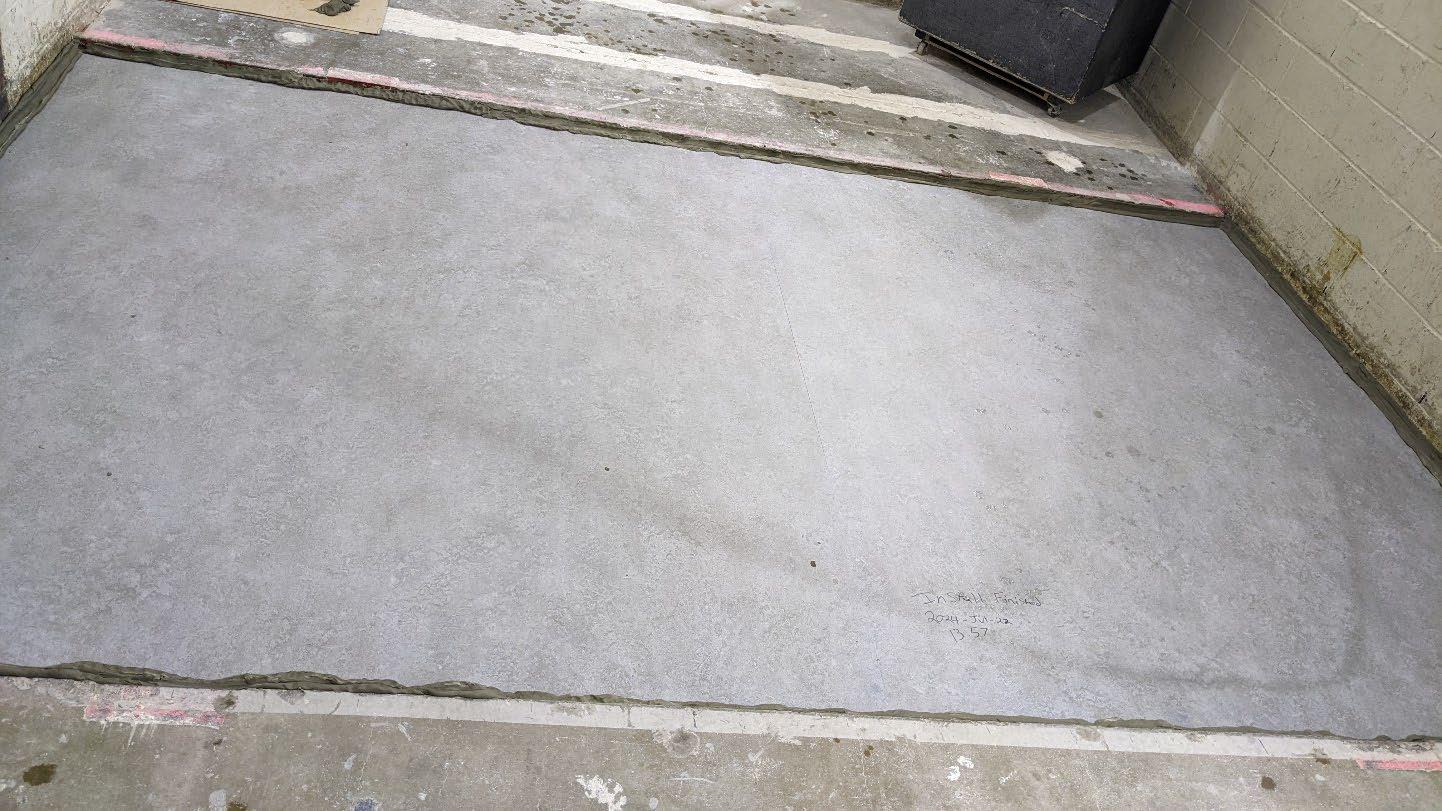
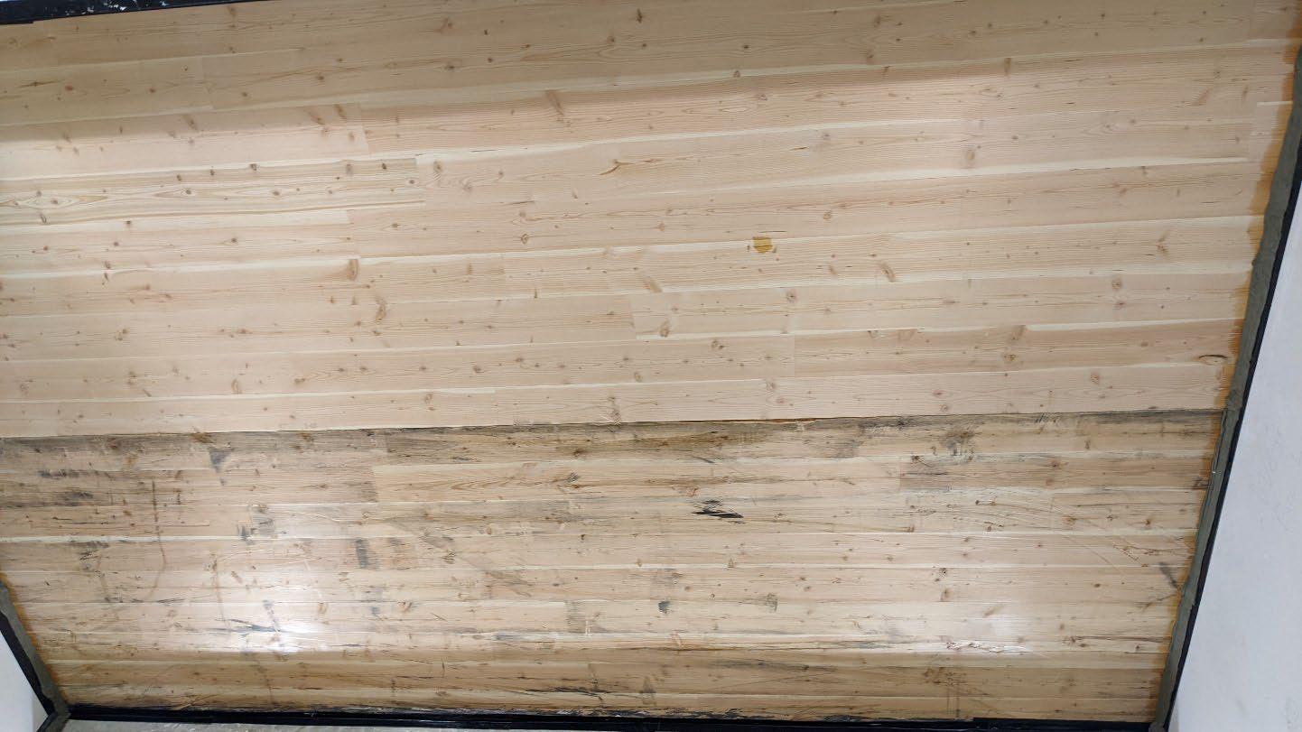
University of Oregon
2024-07-25
Page 7 of 17
University of Oregon
2024-07-25
Page 8 of 17
University of Oregon
2024-07-25 Page 9 of 17
University of Oregon
2024-07-25
Page 10 of 17
University of Oregon
2024-07-25 Page 11 of 17
University of Oregon
2024-07-25 Page 12 of 17
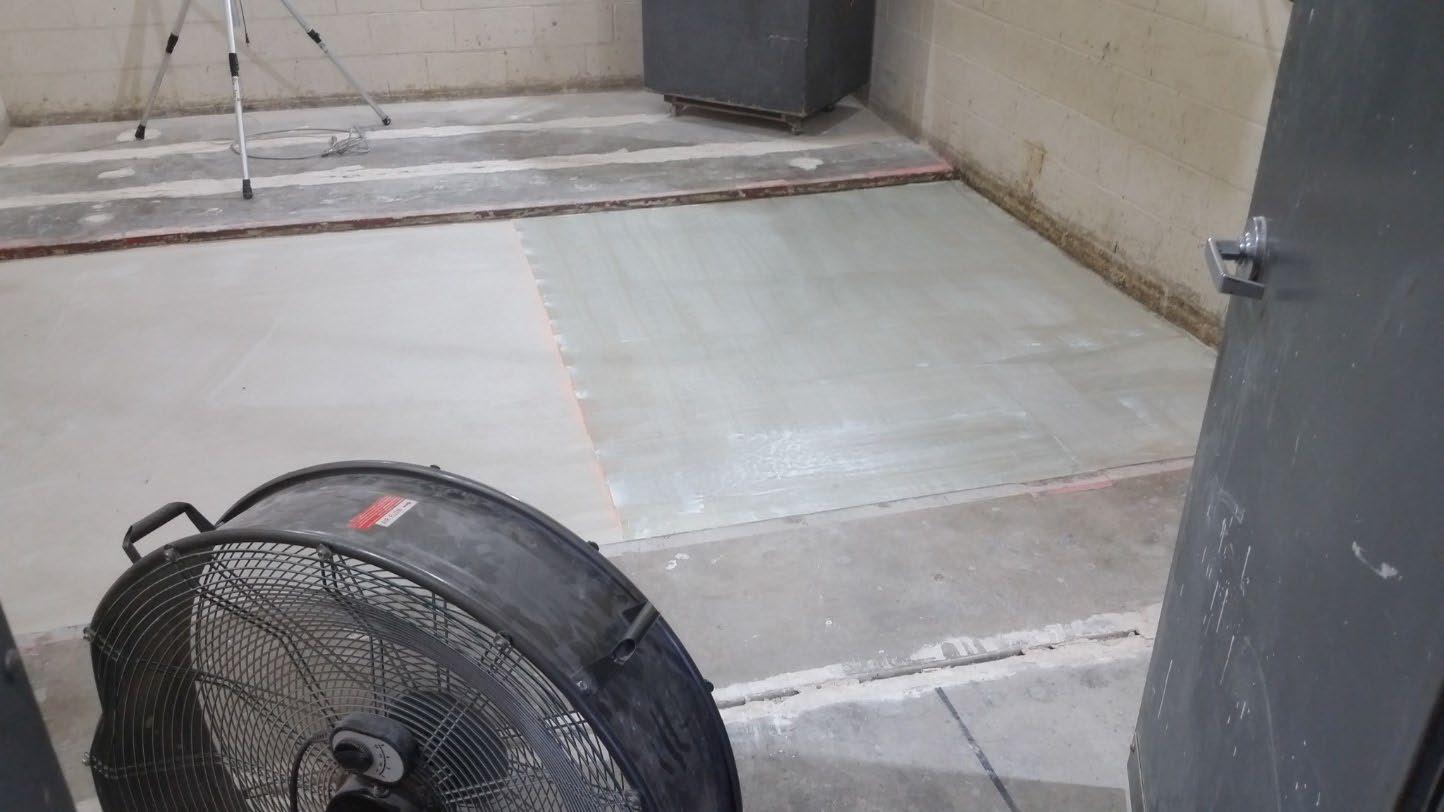
University of Oregon
2024-07-25 Page 13 of 17
The averaged sound pressure levels, normalized to a receive room reference absorption of 10 m2, are tabulated at the sixteen frequency bands specified in ASTM E492-22 Section 9.5. A graphic presentation of the data and additional information appear on the following pages. The 95% confidence limit for the sound pressure level in the receive room is below the limits specified in ASTM E492-22 Section A1.4.
IIC=47
ABBREVIATION INDEX
FREQ. = 1/3 OCTAVE BAND CENTER FREQUENCY, Hz
Ln = NORMALIZED SOUND PRESSURE LEVEL, dB
ΔLn = 95% UNCERTAINTY LIMIT FOR Ln, dB
DEV. = DEVIATION FROM SHIFTED IIC CONTOUR, dB (SUM OF DEV = 14 ) IIC = IMPACT INSULATION CLASS
LEVEL CORRECTED DUE TO
Tested by______________________________ Report by__________________________
Keith Kimberling
Keith Kimberling Test Engineer Test Engineer
Approved by_______________________
Laboratory Manager
627 RIVERBANK DRIVE GENEVA, IL 60134 630-232-0104
University of Oregon
2024-07-25
Page 14 of 17
Marmoleum Decibel adhered with Sustain 1195, 1” Maxxon gypcrete 2000 Multifamily, Certainteed
MemBrain vapor retarder, 3” of 3/8” limestone chip, Hempitecture 2” hemp fiber board, Vaagen Timbers 5-ply CLT 6.875” with plywood spline 3/4”x6” at the joint secured with #9x3” screws at 6” OC
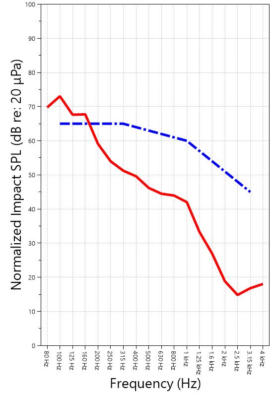
627 RIVERBANK DRIVE GENEVA, IL 60134 630-232-0104
University of Oregon
2024-07-25
Page 15 of 17
Specimen: Marmoleum Decibel adhered with Sustain 1195, 1” Maxxon gypcrete 2000 Multifamily, Certainteed MemBrain vapor retarder, 3” of 3/8” limestone chip, Hempitecture 2” hemp fiber board, Vaagen Timbers 5ply CLT 6.875” with plywood spline 3/4”x6” at the joint secured with #9x3” screws at 6” OC (See Full Report)
The following non-accredited data were obtained in accordance with ASTM E492-22 but extend beyond the frequency range of 100 Hz to 3,150 Hz specified in Section 9.5. These unofficial results are representative of the RAL test environment only and intended for research & comparison purposes. 1/3 Octave Band
* Level corrected due to proximity to background noise per E492 Section 10.2.2
** Level corrected due to proximity to background noise per E492 Section 10.2.3, represents lower bound of specimen performance
627 RIVERBANK DRIVE GENEVA, IL 60134 630-232-0104
University of Oregon RAL™-IN24-023 2024-07-25
Page 16 of 17
Specimen: Marmoleum Decibel adhered with Sustain 1195, 1” Maxxon gypcrete 2000 Multifamily, Certainteed MemBrain vapor retarder, 3” of 3/8” limestone chip, Hempitecture 2” hemp fiber board, Vaagen Timbers 5-ply CLT 6.875” with plywood spline 3/4”x6” at the joint secured with #9x3” screws at 6” OC (See Full Report)
ΔLn, the 95% confidence limit for the reported normalized sound pressure level, is calculated from the standard deviation of the set of sound pressure levels measured during this individual test. This metric is calculated in an effort to quantify the variability in measured levels due to the combined influences of varying sound pressure level in the receive room and changes in specimen response for different tapping machine locations.
Repeatability, expressed as a 95% confidence limit, is calculated from the standard deviation in normalized sound pressure level as obtained from a total of six consecutive tests conducted according to this test method by RAL from 2019-02-07 to 2019-02-12. The tests were performed on a specimen composed of 152.4 mm (6 in.) thick concrete slabs, which was left installed and unaltered between tests. This metric provides an estimate of the variation in results that might be observed if the test were repeated with no change to the installed specimen. Note that repeatability will vary with the construction type.
Specimen: Marmoleum Decibel adhered with Sustain 1195, 1” Maxxon gypcrete 2000 Multifamily, Certainteed MemBrain vapor retarder, 3” of 3/8” limestone chip, Hempitecture 2” hemp fiber board, Vaagen Timbers 5-ply CLT 6.875” with plywood spline 3/4”x6” at the joint secured with #9x3” screws at 6” OC (See Full Report)
Current priorities in the architectural acoustics community involve the development of impact insulation metrics corresponding to impact sources of varying frequency content. Standard Classification ASTM E3222-20a provides a method for calculating the High-Frequency Impact Insulation Class (HIIC), using normalized impact sound pressure level (Ln) data at frequency bands from 400 Hz to 3150 Hz. Standard Classification ASTM E3207-21 provides a method for calculating the Low-Frequency Impact Insulation Class (LIIC) uses normalized impact sound pressure level (Ln) data at frequency bands from 50 Hz to 80 Hz.
Low-frequency impact noise correlates to the “thudding” of footfalls on lightweight structures, while highfrequency sound correlates to sources including the impacts of hard-heeled shoes, dragging furniture, dog toenails, and objects dropped on hard-surfaced flooring. When presented alongside the IIC rating, The LIIC and HIIC ratings can be used to predict how the nature of an impact source will affect the response of the floor-ceiling construction. A summary of impact insulation ratings, as calculated from the test results, is given below.
627 RIVERBANK DRIVE GENEVA, IL 60134 630-232-0104
University of Oregon RAL™-IN24-023 2024-07-25 Page 17 of 17
Specimen: Marmoleum Decibel adhered with Sustain 1195, 1” Maxxon gypcrete 2000 Multifamily, Certainteed MemBrain vapor retarder, 3” of 3/8” limestone chip, Hempitecture 2” hemp fiber board, Vaagen Timbers 5-ply CLT 6.875” with plywood spline 3/4”x6” at the joint secured with #9x3” screws at 6” OC (See Full Report)
Description
System 2 Type 3160-A-042 3160106974 2023-08-11 2024-08-11
Bruel & Kjaer Mic And Preamp C Type 4943-B-001 2311439 2024-03-29 2025-03-29
Bruel & Kjaer Sound Level
Calibrator Type 4230 861609 2023-12-20 2024-12-20
Bruel & Kjaer Tapping Machine Type 3207 3151105 2023-12-14 2024-12-14
EXTECH Hygro 959 SD700 A.099959 2024-03-29 2025-03-29
EXTECH Hygro 639 SD700 A.103639 2023-12-01 2024-12-01
Specimen: Marmoleum Decibel adhered with Sustain 1195, 1” Maxxon gypcrete 2000 Multifamily, Certainteed MemBrain vapor retarder, 3” of 3/8” limestone chip, Hempitecture 2” hemp fiber board, Vaagen Timbers 5-ply CLT 6.875” with plywood spline 3/4”x6” at the joint secured with #9x3” screws at 6” OC (See Full Report)
Date Revision
2024-07-31 Original report issued
2024-09-19 Page 17: Calibrator device description corrected and tapping machine added to instruments of traceability -EPW
627 RIVERBANK DRIVE
GENEVA, IL 60134
630-232-0104
SPONSOR: University of Oregon Sound Transmission Loss Portland, OR RAL™-TL24-278
CONDUCTED: 2024-06-21 Page 1 of 20 ON: Marmoleum Decibel adhered with Sustain 1195, 1-1/8” T&G plywood subfloor screwed 24” OC with #9x3", cavity filled with: 3.75” of 3/8" limestone chip, 2x4 sleepers 24”OC with Rothoblaas Piano B acoustic strips stapled top/bottom, Vaagen Timbers 5-ply CLT 6.875” with plywood spline 3/4”x6” at the joint secured with #9x3” screws at 6” OC
Riverbank Acoustical Laboratories™ is accredited by the U.S. Department of Commerce, National Institute of Standards and Technology (NIST) under the National Voluntary Laboratory Accreditation Program (NVLAP) as an ISO 17025:2017 Laboratory (NVLAP Lab Code: 100227-0) and for this test procedure. The test reported in this document conformed explicitly with ASTM E90-09 (2016): "Standard Test Method for Laboratory Measurement of Airborne Sound Transmission Loss of Building Partitions and Elements." The single number rating of the specimen was calculated according to ASTM E413-22: "Classification for Rating Sound Insulation." A description of the measurement procedure and room specifications is available upon request. The transmission loss values are for a single direction of measurement. The results presented in this report apply to the sample as received from the test sponsor.
The test specimen was designated by the sponsor as Marmoleum Decibel adhered with Sustain 1195, 11/8” T&G plywood subfloor screwed 24” OC with #9x3", cavity filled with: 3.75” of 3/8" limestone chip, 2x4 sleepers 24”OC with Rothoblaas Piano B acoustic strips stapled top/bottom, Vaagen Timbers 5-ply CLT 6.875” with plywood spline 3/4”x6” at the joint secured with #9x3” screws at 6” OC. The following nominal product information was provided by the sponsor prior to testing. The accuracy of such sponsorprovided information can affect the validity of the test results.
Provided Description: Marmoleum Decibel adhered with Sustain 1195, 1-1/8” T&G plywood subfloor screwed 24” OC with #9x3", cavity filled with: 3.75” of 3/8" limestone chip, 2x4 sleepers 24”OC with Rothoblaas Piano B acoustic strips stapled top/bottom, Vaagen Timbers 5-ply CLT 6.875” with plywood spline 3/4”x6” at the joint secured with #9x3” screws at 6” OC Manufacturer: University of Oregon
OF RAL. THE RESULTS REPORTED APPLY ONLY TO THE SPECIFIC SAMPLE SUBMITTED FOR TESTING; RAL ASSUMES NO RESPONSIBILITY FOR THE PERFORMANCE OF ANY OTHER SAMPLE www.riverbankacoustics.com FOUNDED
627 RIVERBANK DRIVE GENEVA, IL 60134 630-232-0104
University of Oregon
2024-06-21
Page 2 of 20
The building contractor (Seth Priser) and RAL staff compiled a detailed construction specification as follows:
Cross-Laminated Timber (CLT)
Materials: 5-Ply Cross-Laminated Timber
Dimensions: 2 panels @ 1219 mm (48 in.) by 4229 mm (166.5 in.)
Thickness: 171 mm (6.75 in.)
Overall Weight: 953.45 kg (2102 lbs)
Mass Per Unit Volume: 539 kg/m3 (33.7 lbs/ft3)
Installation: CLT panels laid on 152 mm (6 in.) wide knee walls in test opening and butted to one another without sealant/adhesive.
3/4”x3” Rabbet on top side of one edge of each panel where they butt allowing a loose spline (below) to insert and join the two
¾” CDX Loose Spline
Materials: 3/4” x 6” plywood spline
Dimensions: 1 piece @ 151 mm (5.9375 in.) wide by 2438 mm (96 in.) 1 piece @ 151 mm (5.9375 in.) wide by 1791 mm (70.5 in.)
Thickness: 19 mm (0.75 in.)
Overall Weight: 6.46 kg (14.25 lbs)
Mass Per Unit Length: 1.53 kg/m (1.03 lbs/ft)
Installation: Set in Rabbets of both CLT’s and screwed in place.
Fasteners: WSV Bugle head sub-floor screws, length @ 76 mm (3 in.)
Fastener Spacing: 6” o.c. on a line 3” from each edge of the spline (Centered on the rabbet of the CLT)
Piano B 40/40 (Lower Layer)
Manufacturer: Rothoblaas
Dimensions: 2 strips @ 40 mm (1.5625 in.) wide by 4267 mm (168 in.) long 8 strips @ 2362 mm (93 in.) wide by 40 mm (1.5625 in.) long
Thickness: 6.76 mm (0.266 in.)
Overall Weight: 4.59 kg (10.125 lbs)
Mass Per Unit Volume: 624 kg/m3 (40.0 lbs/ft3)
Installation: Fastened to underside of 2” x 4” wood sleepers with staples
Fasteners: Arrow staples, length @ 13 mm (0.5 in.)
University of Oregon
2024-06-21
SPECIMEN MEASUREMENTS & TEST CONDITIONS (continued)
2” by 4” SPF Framing Sleepers
Materials: Nominal 2”x 4” framing lumber
Page 3 of 20
Dimensions: 2 pieces @ 38 mm (1.5 in.) wide by 4255 mm (167.5 in.) long
8 pieces @ 2369 mm (93.25 in.) wide by 38 mm (1.5 in.) long
Depth: 89 mm (3.5 in.)
Overall Weight: 49.33 kg (108.75 lbs)
Mass Per Unit Length: 1.80 kg/m (1.21 lbs/ft)
Installation: Sleepers laid over CLT, resting on lower layer Piano B 40/40
Longer sleepers parallel to CLT like a rim joist
Shorter sleepers set like floor joists between rim joists
Shorter sleepers spaced approx. 610 mm (24 in.) on center
Shorter sleepers fastened to longer sleepers with screws, 2 screws per connection point
Fasteners: WSV Bugle head sub-floor screws, length @ 76 mm (3 in.)
Piano B 40/40 (Upper Layer)
Manufacturer: Rothoblaas
Dimensions: 2 strips @ 40 mm (1.5625 in.) wide by 4267 mm (168 in.) long
8 strips @ 2362 mm (93 in.) wide by 40 mm (1.5625 in.) long
Thickness: 6.76 mm (0.266 in.)
Overall Weight: 4.59 kg (10.125 lbs)
Mass Per Unit
Volume: 624 kg/m3 (40.0 lbs/ft3)
Installation: Fastened to top of 2” x 4” wood sleepers with staples
Fasteners: Arrow staples, length @ 13 mm (0.5 in.)
Crushed Limestone
Materials: CA-16 3/8” chip crushed limestone
Dimensions: 2438 mm (96 in.) wide by 4267 mm (168 in.) long, as installed
Depth: 95 mm (3.75 in.)
Overall Weight: 1261.89 kg (2782 lbs)
Installation: Filled stone in between sleepers and used a screed to level to the top of the sleepers.
University of Oregon
2024-06-21
SPECIMEN MEASUREMENTS & TEST CONDITIONS (continued)
Plywood Subfloor
Materials: T&G Plywood
Dimensions: 1 piece @ 1219 mm (48 in.) wide by 1829 mm (72 in.)
1 piece @ 1219 mm (48 in.) wide by 2438 mm (96 in.)
1 piece @ 1219 mm (48 in.) wide by 1813 mm (71.375 in.)
1 piece @ 1219 mm (48 in.) wide by 2426 mm (95.5 in.)
Thickness: 29 mm (1.125 in.)
Overall Weight: 176.33 kg (388.75 lbs)
Mass Per Unit Volume: 595 kg/m3 (37.1 lbs/ft3)
Installation: Placed over upper layer Piano B 40/40 over sleepers
Fastened to sleepers through Piano B 40/40 with screws
Plywood piece joints staggered
Fasteners: WSV Bugle head sub-floor screws, length @ 76 mm (3 in.)
Fastener Spacing: 610 mm (24 in.) on center
Adhesive
Materials: Sustain 1195 Sheet and Tile adhesive
Manufacturer: Forbo
Dimensions: Approx. 2438 mm (96 in.) by 4267 mm (168 in.) as installed
Overall Weight: 4.54 kg (10 lbs)
Mass Per Unit Area: 0.44 kg/m2 (0.09 lbs/ft2)
Flooring
Page 4 of 20
Installation: Troweled directly to plywood with a 1/16x1/16x1/16 square notch trowel Once troweled, adhesive was left “open” for 7-10 min to allow it to “tack” before flooring was installed.
Materials: Marmoleum Decibel
Manufacturer: Forbo
Dimensions: 2 pieces @ 2007 mm (79 in.) by 2464 mm (97 in.)
1 piece @ 257 mm (10.125 in.) by 2438 mm (96 in.)
Thickness: 6 mm (0.25 in.)
Overall Weight: 32.77 kg (72.25 lbs)
Mass Per Unit Volume: 491 kg/m3 (30.6 lbs/ft3)
Installation: Two (2) 79” segments perpendicular to Plywood 10” strip to complete Joints staggered from parallel plywood joints by + 6”
Rolled with 100lb roller in each direction
University of Oregon
2024-06-21 Page 5 of 20
SPECIMEN MEASUREMENTS & TEST CONDITIONS (continued)
Overall Specimen Measurements
Dimensions: 2.44 m (96.0 in) wide by 3.86 m (152.0 in) high
Thickness: 0.31 m (12.125 in)
Weight: 2493.96 kg (5498.25 lbs)
Overall Area: 9.414 m² (101.33 ft²)
Mass per Unit Area: 239.69 kg/m² (49.09 lbs/ft²)
Test Aperture
Opening Size: 4.27 m (14.0 ft) x 6.10 m (20.0 ft)
Filler Wall: Yes
Aperture Size: 2.44 m (96.0 in) wide by 3.86 m (152.0 in) high
Transmission Area: 9.414 m² (101.33 ft²)
Sealed: Entire periphery (both sides) with dense mastic
Test Environment
Source Room
Volume: 131.12 m³
Temperature: 22.8 °C ± 0.0 °C
Relative Humidity: 58.5 % ± 1.0 %
Receive Room
Volume: 81.44 m³
Temperature: 21.1 °C ± 0.0 °C
Relative Humidity: 61.0 % ± 0.0 %
Requirements
Temperature: 22º C +/- 2° C, not more than 3° C change over all tests.
Relative Humidity: ≥ 30%, not more than +/- 3% change over all tests.
University of Oregon
2024-06-21
Page 6 of 20
University of Oregon
2024-06-21
Page 7 of 20
University of Oregon
2024-06-21 Page 8 of 20
University of Oregon
2024-06-21 Page 9 of 20
University of Oregon
2024-06-21 Page 10 of 20
University of Oregon
2024-06-21 Page 11 of 20
University of Oregon
2024-06-21 Page 12 of 20
University of Oregon
2024-06-21 Page 13 of 20
University of Oregon
2024-06-21 Page 14 of 20
University of Oregon
2024-06-21 Page 15 of 20
Sound transmission loss values are tabulated at the eighteen standard frequency bands. A graphic presentation of the data and additional information appear on the following pages. The precision of the transmission loss test data is within the limits set by the ASTM Standard E90-09 (2016). See Appendix A for identification of corrections applied to the reported data.
ABBREVIATION INDEX
FREQ. = 1/3 OCTAVE BAND CENTER FREQUENCY, Hz
TL = TRANSMISSION LOSS, dB
ΔTL = 95% CONFIDENCE INTERVAL FOR TL MEASUREMENTS, dB
DEF. = DEFICIENCIES, dB BELOW SHIFTED STC CONTOUR (SUM OF DEF = 31)
STC = SOUND TRANSMISSION CLASS
Keith Kimberling Senior Experimentalist Test Engineer

Tested by_____________________________ Report by__________________________

Approved by _______________________
Eric P. Wolfram Laboratory Manager
627 RIVERBANK DRIVE
GENEVA, IL 60134
630-232-0104
University of Oregon
2024-06-21 Page 16 of 20
Marmoleum Decibel adhered with Sustain 1195, 1-1/8” T&G plywood subfloor screwed 24” OC with #9x3", cavity filled with: 3.75” of 3/8" limestone chip, 2x4 sleepers 24”OC with Rothoblaas Piano B acoustic strips stapled top/bottom, Vaagen Timbers 5-ply CLT 6.875” with plywood spline 3/4”x6” at the joint secured with #9x3” screws at 6” OC
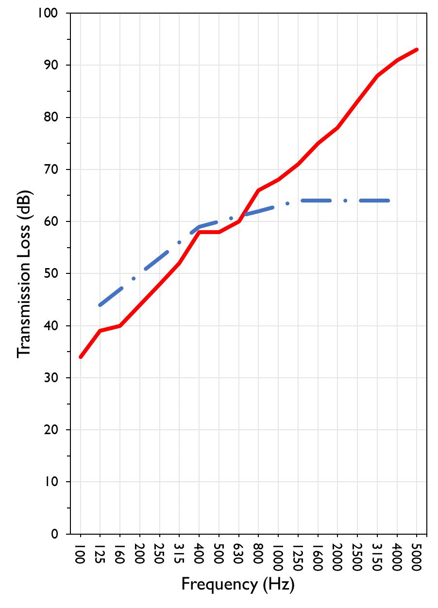
627 RIVERBANK DRIVE GENEVA, IL 60134
630-232-0104
University of Oregon RAL™-TL24-278 2024-06-21 Page 17 of 20
Specimen: Marmoleum Decibel adhered with Sustain 1195, 1-1/8” T&G plywood subfloor screwed 24” OC with #9x3", cavity filled with: 3.75” of 3/8" limestone chip, 2x4 sleepers 24”OC with Rothoblaas Piano B acoustic strips stapled top/bottom, Vaagen Timbers 5-ply CLT 6.875” with plywood spline 3/4”x6” at the joint secured with #9x3” screws at 6” OC (See Full Report)
The following non-accredited data were obtained in accordance with ASTM E90-09 (2016), but extend beyond the defined frequency range of 100Hz to 5,000Hz. These unofficial results are representative of the RAL test environment only and intended for research & comparison purposes. Sampling precision observed during this procedure is reported below. Corrections are detailed in Appendix B.
1/3 Octave Band Sound
627 RIVERBANK DRIVE GENEVA, IL 60134
630-232-0104
University of Oregon
2024-06-21 Page 18 of 20
Specimen: Marmoleum Decibel adhered with Sustain 1195, 1-1/8” T&G plywood subfloor screwed 24” OC with #9x3", cavity filled with: 3.75” of 3/8" limestone chip, 2x4 sleepers 24”OC with Rothoblaas Piano B acoustic strips stapled top/bottom, Vaagen Timbers 5-ply CLT 6.875” with plywood spline 3/4”x6” at the joint secured with #9x3” screws at 6” OC (See Full Report)
Mark Interpretation
A Measured sound pressure levels in the receive room are within 10 dB of the ambient noise level at the marked frequency band. Receive room levels used to calculate Transmission Loss are corrected according to ASTM E90 Section 10.3.
AA Measured sound pressure levels in the receive room are within 5 dB of the ambient noise level at the marked frequency band. Receive room levels used to calculate Transmission Loss are corrected according to ASTM E90 Section 10.3.1. Transmission Loss values calculated from levels corrected this way will be less than or equal to Transmission Loss values from a hypothetical test using the same specimen and a receive room with idealized ambient sound levels of (-∞) dB.
F The reported Transmission Loss is within 10 dB of the laboratory flanking limit at the marked frequency band. The measured performance of the specimen may be limited by the performance of the laboratory building structure at this frequency band.
Z The reported Transmission Loss at the marked frequency band has been corrected according to ASTM E90 Section A3.2.7 to account for possible sound transmission through the filler assembly.
ZZ The reported Transmission Loss at the marked frequency band has been corrected according to ASTM E90 Section A3.2.8 to account for possible sound transmission through the filler assembly. Transmission Loss values corrected this way will be less than or equal to Transmission Loss values from a hypothetical test using the same specimen and an idealized filler assembly with a Sound Transmission Class rating of (∞).
Specimen: Marmoleum Decibel adhered with Sustain 1195, 1-1/8” T&G plywood subfloor screwed 24” OC with #9x3", cavity filled with: 3.75” of 3/8" limestone chip, 2x4 sleepers 24”OC with Rothoblaas Piano B acoustic strips stapled top/bottom, Vaagen Timbers 5-ply CLT 6.875” with plywood spline 3/4”x6” at the joint secured with #9x3” screws at 6” OC (See Full Report)
ΔTL, the 95% confidence interval for reported transmission loss values, is calculated from the standard deviation of the sets of measurements for source room sound pressure level, receive room sound pressure level, and receive room sound absorption. This metric is calculated in an effort to quantify the combined influences of room geometry, microphone positioning, and other varying environmental conditions on reported results.
Repeatability, expressed as a 95% confidence interval, is calculated from the standard deviation of transmission loss as obtained from a set of six (6) consecutive tests conducted according to this test method by RAL from 202102-25 through 2021-03-04. The tests were performed on a specimen composed of a 6 in. thick concrete slab, using the same test opening as used in this report. This metric provides an estimate of the variation in results that might be observed if the test were repeated with no change to the installed specimen. Note that repeatability will vary with the construction type.
1918 BY WALLACE CLEMENT SABINE 627 RIVERBANK DRIVE GENEVA, IL 60134 630-232-0104
University of Oregon RAL™-TL24-278 2024-06-21 Page 19 of 20
APPENDIX D: Determination of Outdoor Indoor Transmission Class (OITC)
Specimen: Marmoleum Decibel adhered with Sustain 1195, 1-1/8” T&G plywood subfloor screwed 24” OC with #9x3", cavity filled with: 3.75” of 3/8" limestone chip, 2x4 sleepers 24”OC with Rothoblaas Piano B acoustic strips stapled top/bottom, Vaagen Timbers 5-ply CLT 6.875” with plywood spline 3/4”x6” at the joint secured with #9x3” screws at 6” OC (See Full Report)
The determination of the Outdoor Indoor Transmission Class (OITC) as reported below was made with explicit conformity to the procedures described in the ASTM E1332-22 test standard. Test Method ASTM E90-09 (2016) was used to obtain the sound transmission loss data. This rating is based on an average transportation noise source spectrum and an A-weighted sound level reduction, either of which may be inappropriate for some applications.
SABINE 627 RIVERBANK DRIVE GENEVA, IL 60134 630-232-0104
University of Oregon RAL™-TL24-278 2024-06-21 Page 20 of 20
APPENDIX E: Instruments of Traceability
1918 BY
Specimen: Marmoleum Decibel adhered with Sustain 1195, 1-1/8” T&G plywood subfloor screwed 24” OC with #9x3", cavity filled with: 3.75” of 3/8" limestone chip, 2x4 sleepers 24”OC with Rothoblaas Piano B acoustic strips stapled top/bottom, Vaagen Timbers 5-ply CLT 6.875” with plywood spline 3/4”x6” at the joint secured with #9x3” screws at 6” OC (See Full Report)
Description
System 2 Type 3160-A-042 3160106974 2023-08-11 2024-08-11
Bruel & Kjaer Mic And Preamp C Type 4943-B-001 2311439 2024-03-29 2025-03-29
Bruel & Kjaer Pistonphone Type 4228 2781248 2023-07-12 2024-07-12
EXTECH Hygro 663 SD700 A083663 2023-12-28 2024-12-28
EXTECH Hygro 639 SD700 A.103639 2023-12-01 2024-12-01
APPENDIX F: Revisions to Original Test Report
Specimen: Marmoleum Decibel adhered with Sustain 1195, 1-1/8” T&G plywood subfloor screwed 24” OC with #9x3", cavity filled with: 3.75” of 3/8" limestone chip, 2x4 sleepers 24”OC with Rothoblaas Piano B acoustic strips stapled top/bottom, Vaagen Timbers 5-ply CLT 6.875” with plywood spline 3/4”x6” at the joint secured with #9x3” screws at 6” OC (See Full Report)
Date Revision 2024-07-31 Original report issued
627 RIVERBANK DRIVE
GENEVA, IL 60134
630-232-0104
www.riverbankacoustics.com FOUNDED 1918
SPONSOR: University of Oregon Sound Transmission Loss Portland, OR RAL™-TL24-279
CONDUCTED: 2024-06-24
Page 1 of 17 ON: 1-1/8” T&G plywood subfloor screwed 24” OC with #9x3”, cavity filled with: 3” of 3/8” limestone chip and Hempitecture 3/4” hemp fiber board, 2x4 sleepers 24”OC with Rothoblaas Piano B acoustic strips stapled top/bottom, Vaagen Timbers 5-ply CLT 6.875” with plywood spline 3/4”x6” at the joint secured with #9x3” screws at 6” OC
Riverbank Acoustical Laboratories™ is accredited by the U.S. Department of Commerce, National Institute of Standards and Technology (NIST) under the National Voluntary Laboratory Accreditation Program (NVLAP) as an ISO 17025:2017 Laboratory (NVLAP Lab Code: 100227-0) and for this test procedure. The test reported in this document conformed explicitly with ASTM E90-09 (2016): "Standard Test Method for Laboratory Measurement of Airborne Sound Transmission Loss of Building Partitions and Elements." The single number rating of the specimen was calculated according to ASTM E413-22: "Classification for Rating Sound Insulation." A description of the measurement procedure and room specifications is available upon request. The transmission loss values are for a single direction of measurement. The results presented in this report apply to the sample as received from the test sponsor.
The test specimen was designated by the sponsor as 1-1/8” T&G plywood subfloor screwed 24” OC with #9x3”, cavity filled with: 3” of 3/8” limestone chip and Hempitecture 3/4” hemp fiber board, 2x4 sleepers 24”OC with Rothoblaas Piano B acoustic strips stapled top/bottom, Vaagen Timbers 5-ply CLT 6.875” with plywood spline 3/4”x6” at the joint secured with #9x3” screws at 6” OC. The following nominal product information was provided by the sponsor prior to testing. The accuracy of such sponsor-provided information can affect the validity of the test results.
Provided Description: 1-1/8” T&G plywood subfloor screwed 24” OC with #9x3", cavity filled with: 3” of 3/8" limestone chip and Hempitecture 3/4” hemp fiber board, 2x4 sleepers 24”OC with Rothoblaas Piano B acoustic strips stapled top/bottom, Vaagen Timbers 5-ply CLT 6.875"
Manufacturer: University of Oregon
OF RAL. THE RESULTS REPORTED APPLY ONLY TO THE SPECIFIC SAMPLE SUBMITTED FOR TESTING; RAL ASSUMES NO RESPONSIBILITY FOR THE PERFORMANCE OF ANY OTHER SAMPLE
627 RIVERBANK DRIVE GENEVA, IL 60134 630-232-0104
University of Oregon
2024-06-24
Page 2 of 17
The building contractor (Seth Priser) and RAL staff compiled a detailed construction specification as follows:
Cross-Laminated Timber (CLT)
Materials: 5-Ply Cross-Laminated Timber
Dimensions: 2 panels @ 1219 mm (48 in.) by 4229 mm (166.5 in.)
Thickness: 171 mm (6.75 in.)
Overall Weight: 953.45 kg (2102 lbs)
Mass Per Unit Volume: 539 kg/m3 (33.7 lbs/ft3)
Installation: CLT panels laid on 152 mm (6 in.) wide knee walls in test opening and butted to one another without sealant/adhesive.
3/4”x3” Rabbet on top side of one edge of each panel where they butt allowing a loose spline (below) to insert and join the two
¾” CDX Loose Spline
Materials: 3/4” x 6” plywood spline
Dimensions: 1 piece @ 151 mm (5.9375 in.) wide by 2438 mm (96 in.) 1 piece @ 151 mm (5.9375 in.) wide by 1791 mm (70.5 in.)
Thickness: 19 mm (0.75 in.)
Overall Weight: 6.46 kg (14.25 lbs)
Mass Per Unit Length: 1.53 kg/m (1.03 lbs/ft)
Installation: Set in Rabbets of both CLT’s and screwed in place.
Fasteners: WSV Bugle head sub-floor screws, length @ 76 mm (3 in.)
Fastener Spacing: 6” o.c. on a line 3” from each edge of the spline (Centered on the rabbet of the CLT)
Piano B 40/40 (Lower Layer)
Manufacturer: Rothoblaas
Dimensions: 2 strips @ 40 mm (1.5625 in.) wide by 4267 mm (168 in.) long 8 strips @ 2362 mm (93 in.) wide by 40 mm (1.5625 in.) long
Thickness: 6.76 mm (0.266 in.)
Overall Weight: 4.59 kg (10.125 lbs)
Mass Per Unit Volume: 624 kg/m3 (40.0 lbs/ft3)
Installation: Fastened to underside of 2” x 4” wood sleepers with staples
Fasteners: Arrow staples, length @ 13 mm (0.5 in.)
University of Oregon
2024-06-24
SPECIMEN MEASUREMENTS & TEST CONDITIONS (continued)
2” by 4” SPF Framing Sleepers
Materials: Nominal 2”x 4” framing lumber
Page 3 of 17
Dimensions: 2 pieces @ 38 mm (1.5 in.) wide by 4255 mm (167.5 in.) long
8 pieces @ 2369 mm (93.25 in.) wide by 38 mm (1.5 in.) long
Depth: 89 mm (3.5 in.)
Overall Weight: 49.33 kg (108.75 lbs)
Mass Per Unit Length: 1.80 kg/m (1.21 lbs/ft)
Installation: Sleepers laid over CLT, resting on lower layer Piano B 40/40
Longer sleepers parallel to CLT like a rim joist
Shorter sleepers set like floor joists between rim joists
Shorter sleepers spaced approx. 610 mm (24 in.) on center
Shorter sleepers fastened to longer sleepers with screws, 2 screws per connection point
Fasteners: WSV Bugle head sub-floor screws, length @ 76 mm (3 in.)
Piano B 40/40 (Upper Layer)
Manufacturer: Rothoblaas
Dimensions: 2 strips @ 40 mm (1.5625 in.) wide by 4267 mm (168 in.) long 8 strips @ 2362 mm (93 in.) wide by 40 mm (1.5625 in.) long
Thickness: 6.76 mm (0.266 in.)
Overall Weight: 4.59 kg (10.125 lbs)
Mass Per Unit Volume: 624 kg/m3 (40.0 lbs/ft3)
Installation: Fastened to top of 2” x 4” wood sleepers with staples
Fasteners: Arrow staples, length @ 13 mm (0.5 in.)
Materials: 1” Hemp fiber board
Manufacturer: Hempitecture
Dimensions: 7 pieces @ 572 mm (22.5 in.) wide by 2369 mm (93.25 in.) long
Depth: 19 mm (0.75 in.)
Overall Weight: 24.38 kg (53.75 lbs)
Mass Per Unit Volume: 135 kg/m3 (8.43 lbs/ft3)
Installation: Friction fit between sleepers and on top of CLT
627 RIVERBANK DRIVE GENEVA, IL 60134
630-232-0104
University of Oregon
2024-06-24
SPECIMEN MEASUREMENTS & TEST CONDITIONS (continued)
Crushed Limestone
Materials: CA-16 3/8” chip crushed limestone
Page 4 of 17
Dimensions: 2438 mm (96 in.) wide by 4267 mm (168 in.) long, as installed
Depth: 70 mm (2.75 in.)
Overall Weight: 986.56 kg (2175 lbs)
Installation: Filled stone in above hemp board and between sleepers and used a screed to level to the top of the sleepers.
Plywood Subfloor
Materials: T&G Plywood
Dimensions: 1 piece @ 1219 mm (48 in.) wide by 1829 mm (72 in.)
1 piece @ 1219 mm (48 in.) wide by 2438 mm (96 in.)
1 piece @ 1219 mm (48 in.) wide by 1822 mm (71.75 in.)
1 piece @ 1219 mm (48 in.) wide by 2432 mm (95.75 in.)
Thickness: 29 mm (1.125 in.)
Overall Weight: 170.66 kg (376.25 lbs)
Mass Per Unit Volume: 575 kg/m3 (35.9 lbs/ft3)
Installation: Placed over upper layer Piano B 40/40 over sleepers
Fastened to sleepers through Piano B 40/40 with screws Plywood piece joints staggered
Fasteners: WSV Bugle head sub-floor screws, length @ 76 mm (3 in.)
Fastener Spacing: 610 mm (24 in.) on center
University of Oregon
2024-06-24
SPECIMEN MEASUREMENTS & TEST CONDITIONS (continued)
Overall Specimen Measurements
Dimensions: 2.44 m (96.0 in) wide by 3.86 m (152.0 in) high
Thickness: 0.3 m (11.875 in)
Weight: 2200.03 kg (4850.25 lbs)
Overall Area: 9.414 m² (101.33 ft²)
Mass per Unit Area: 211.44 kg/m² (43.31 lbs/ft²)
Test Aperture
Opening Size: 4.27 m (14.0 ft) x 6.10 m (20.0 ft)
Filler Wall: Yes
Aperture Size: 2.44 m (96.0 in) wide by 3.86 m (152.0 in) high
Transmission Area: 9.414 m² (101.33 ft²)
Sealed: Entire periphery (both sides) with dense mastic
Test Environment
Source Room
Volume: 131.12 m³
Temperature: 23.3 °C ± 0.0 °C
Relative Humidity: 60.0 % ± 0.0 %
Receive Room
Volume: 81.44 m³
Temperature: 22.2 °C ± 0.0 °C
Relative Humidity: 61.5 % ± 1.0 %
Requirements
Page 5 of 17
Temperature: 22º C +/- 2° C, not more than 3° C change over all tests.
Relative Humidity: ≥ 30%, not more than +/- 3% change over all tests.
University of Oregon
2024-06-24
Page 6 of 17
University of Oregon
2024-06-24
Page 7 of 17
University of Oregon
2024-06-24 Page 8 of 17
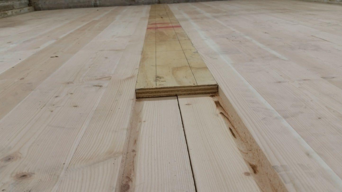
University of Oregon
2024-06-24 Page 9 of 17
University of Oregon
2024-06-24
Page 10 of 17
University of Oregon
2024-06-24 Page 11 of 17
University of Oregon
2024-06-24 Page 12 of 17
Sound transmission loss values are tabulated at the eighteen standard frequency bands. A graphic presentation of the data and additional information appear on the following pages. The precision of the transmission loss test data is within the limits set by the ASTM Standard E90-09 (2016). See Appendix A for identification of corrections applied to the reported data.
ABBREVIATION INDEX
FREQ. = 1/3 OCTAVE BAND CENTER FREQUENCY, Hz
TL = TRANSMISSION LOSS, dB
ΔTL = 95% CONFIDENCE INTERVAL FOR TL MEASUREMENTS, dB
DEF. = DEFICIENCIES, dB BELOW SHIFTED STC CONTOUR (SUM OF DEF = 30)
STC = SOUND TRANSMISSION CLASS

Approved by
Eric P. Wolfram Laboratory Manager
627 RIVERBANK DRIVE
GENEVA, IL 60134
630-232-0104
University of Oregon
2024-06-24
Page 13 of 17
1-1/8” T&G plywood subfloor screwed 24” OC with #9x3”, cavity filled with: 3” of 3/8” limestone chip and Hempitecture 3/4” hemp fiber board, 2x4 sleepers 24”OC with Rothoblaas Piano B acoustic strips stapled top/bottom, Vaagen Timbers 5-ply CLT 6.875” with plywood spline 3/4”x6” at the joint secured with #9x3” screws at 6” OC
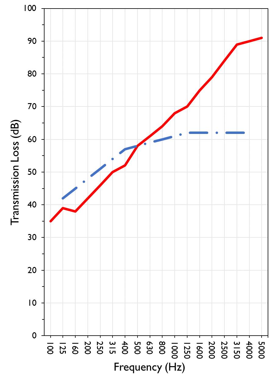
TRANSMISSION LOSS SOUND TRANSMISSION CLASS CONTOUR
627 RIVERBANK DRIVE GENEVA, IL 60134
630-232-0104
University of Oregon
2024-06-24
Page 14 of 17
Specimen: 1-1/8” T&G plywood subfloor screwed 24” OC with #9x3”, cavity filled with: 3” of 3/8” limestone chip and Hempitecture 3/4” hemp fiber board, 2x4 sleepers 24”OC with Rothoblaas Piano B acoustic strips stapled top/bottom, Vaagen Timbers 5-ply CLT 6.875” with plywood spline 3/4”x6” at the joint secured with #9x3” screws at 6” OC (See Full Report)
The following non-accredited data were obtained in accordance with ASTM E90-09 (2016), but extend beyond the defined frequency range of 100Hz to 5,000Hz. These unofficial results are representative of the RAL test environment only and intended for research & comparison purposes. Sampling precision observed during this procedure is reported below. Corrections are detailed in Appendix B.
1/3 Octave Band Sound
627 RIVERBANK DRIVE GENEVA, IL 60134
630-232-0104
University of Oregon
2024-06-24
Page 15 of 17
Specimen: 1-1/8” T&G plywood subfloor screwed 24” OC with #9x3”, cavity filled with: 3” of 3/8” limestone chip and Hempitecture 3/4” hemp fiber board, 2x4 sleepers 24”OC with Rothoblaas Piano B acoustic strips stapled top/bottom, Vaagen Timbers 5-ply CLT 6.875” with plywood spline 3/4”x6” at the joint secured with #9x3” screws at 6” OC (See Full Report)
Mark Interpretation
A Measured sound pressure levels in the receive room are within 10 dB of the ambient noise level at the marked frequency band. Receive room levels used to calculate Transmission Loss are corrected according to ASTM E90 Section 10.3.
AA Measured sound pressure levels in the receive room are within 5 dB of the ambient noise level at the marked frequency band. Receive room levels used to calculate Transmission Loss are corrected according to ASTM E90 Section 10.3.1. Transmission Loss values calculated from levels corrected this way will be less than or equal to Transmission Loss values from a hypothetical test using the same specimen and a receive room with idealized ambient sound levels of (-∞) dB.
F The reported Transmission Loss is within 10 dB of the laboratory flanking limit at the marked frequency band. The measured performance of the specimen may be limited by the performance of the laboratory building structure at this frequency band.
Z The reported Transmission Loss at the marked frequency band has been corrected according to ASTM E90 Section A3.2.7 to account for possible sound transmission through the filler assembly.
ZZ The reported Transmission Loss at the marked frequency band has been corrected according to ASTM E90 Section A3.2.8 to account for possible sound transmission through the filler assembly. Transmission Loss values corrected this way will be less than or equal to Transmission Loss values from a hypothetical test using the same specimen and an idealized filler assembly with a Sound Transmission Class rating of (∞).
Specimen: 1-1/8” T&G plywood subfloor screwed 24” OC with #9x3”, cavity filled with: 3” of 3/8” limestone chip and Hempitecture 3/4” hemp fiber board, 2x4 sleepers 24”OC with Rothoblaas Piano B acoustic strips stapled top/bottom, Vaagen Timbers 5-ply CLT 6.875” with plywood spline 3/4”x6” at the joint secured with #9x3” screws at 6” OC
(See Full Report)
ΔTL, the 95% confidence interval for reported transmission loss values, is calculated from the standard deviation of the sets of measurements for source room sound pressure level, receive room sound pressure level, and receive room sound absorption. This metric is calculated in an effort to quantify the combined influences of room geometry, microphone positioning, and other varying environmental conditions on reported results.
Repeatability, expressed as a 95% confidence interval, is calculated from the standard deviation of transmission loss as obtained from a set of six (6) consecutive tests conducted according to this test method by RAL from 202102-25 through 2021-03-04. The tests were performed on a specimen composed of a 6 in. thick concrete slab, using the same test opening as used in this report. This metric provides an estimate of the variation in results that might be observed if the test were repeated with no change to the installed specimen. Note that repeatability will vary with the construction type.
RIVERBANK DRIVE GENEVA, IL 60134 630-232-0104
University of Oregon RAL™-TL24-279 2024-06-24 Page 16 of 17
APPENDIX D: Determination of Outdoor Indoor Transmission Class (OITC)
Specimen: 1-1/8” T&G plywood subfloor screwed 24” OC with #9x3”, cavity filled with: 3” of 3/8” limestone chip and Hempitecture 3/4” hemp fiber board, 2x4 sleepers 24”OC with Rothoblaas Piano B acoustic strips stapled top/bottom, Vaagen Timbers 5-ply CLT 6.875” with plywood spline 3/4”x6” at the joint secured with #9x3” screws at 6” OC (See Full Report)
The determination of the Outdoor Indoor Transmission Class (OITC) as reported below was made with explicit conformity to the procedures described in the ASTM E1332-22 test standard. Test Method ASTM E90-09 (2016) was used to obtain the sound transmission loss data. This rating is based on an average transportation noise source spectrum and an A-weighted sound level reduction, either of which may be inappropriate for some applications.
627 RIVERBANK DRIVE GENEVA, IL 60134 630-232-0104
University of Oregon RAL™-TL24-279 2024-06-24 Page 17 of 17
APPENDIX E: Instruments of Traceability
Specimen: 1-1/8” T&G plywood subfloor screwed 24” OC with #9x3”, cavity filled with: 3” of 3/8” limestone chip and Hempitecture 3/4” hemp fiber board, 2x4 sleepers 24”OC with Rothoblaas Piano B acoustic strips stapled top/bottom, Vaagen Timbers 5-ply CLT 6.875” with plywood spline 3/4”x6” at the joint secured with #9x3” screws at 6” OC (See Full Report)
Description
System 2 Type 3160-A-042 3160106974 2023-08-11 2024-08-11
Bruel & Kjaer Mic And Preamp C Type 4943-B-001 2311439 2024-03-29 2025-03-29
Bruel & Kjaer Pistonphone Type 4228 2781248 2023-07-12 2024-07-12
EXTECH Hygro 663 SD700 A083663 2023-12-28 2024-12-28
EXTECH Hygro 639 SD700 A.103639 2023-12-01 2024-12-01
APPENDIX F: Revisions to Original Test Report
Specimen: 1-1/8” T&G plywood subfloor screwed 24” OC with #9x3”, cavity filled with: 3” of 3/8” limestone chip and Hempitecture 3/4” hemp fiber board, 2x4 sleepers 24”OC with Rothoblaas Piano B acoustic strips stapled top/bottom, Vaagen Timbers 5-ply CLT 6.875” with plywood spline 3/4”x6” at the joint secured with #9x3” screws at 6” OC (See Full Report)
Date Revision 2024-07-31 Original report issued
627 RIVERBANK DRIVE
GENEVA, IL 60134
630-232-0104
SPONSOR: University of Oregon Sound Transmission Loss Portland, OR RAL™-TL24-280
CONDUCTED: 2024-06-25 Page 1 of 20 ON: Marmoleum Decibel adhered with Sustain 1195, 1-1/8” T&G plywood subfloor screwed 24” OC with #9x3", cavity filled with: 3” of 3/8" limestone chip and Hempitecture 3/4” hemp fiber board, 2x4 sleepers 24”OC with Rothoblaas Piano B acoustic strips stapled top/bottom, Vaagen Timbers 5-ply CLT 6.875” with plywood spline 3/4”x6” at the joint secured with #9x3” screws at 6” OC
Riverbank Acoustical Laboratories™ is accredited by the U.S. Department of Commerce, National Institute of Standards and Technology (NIST) under the National Voluntary Laboratory Accreditation Program (NVLAP) as an ISO 17025:2017 Laboratory (NVLAP Lab Code: 100227-0) and for this test procedure. The test reported in this document conformed explicitly with ASTM E90-09 (2016): "Standard Test Method for Laboratory Measurement of Airborne Sound Transmission Loss of Building Partitions and Elements." The single number rating of the specimen was calculated according to ASTM E413-22: "Classification for Rating Sound Insulation." A description of the measurement procedure and room specifications is available upon request. The transmission loss values are for a single direction of measurement. The results presented in this report apply to the sample as received from the test sponsor.
The test specimen was designated by the sponsor as Marmoleum Decibel adhered with Sustain 1195, 11/8” T&G plywood subfloor screwed 24” OC with #9x3", cavity filled with: 3” of 3/8" limestone chip and Hempitecture 3/4” hemp fiber board, 2x4 sleepers 24”OC with Rothoblaas Piano B acoustic strips stapled top/bottom, Vaagen Timbers 5-ply CLT 6.875” with plywood spline 3/4”x6” at the joint secured with #9x3” screws at 6” OC. The following nominal product information was provided by the sponsor prior to testing. The accuracy of such sponsor-provided information can affect the validity of the test results.
Provided Description: Marmoleum Decibel adhered with Sustain 1195, 1-1/8” T&G plywood subfloor screwed 24” OC with #9x3", cavity filled with: 3” of 3/8" limestone chip and Hempitecture 3/4” hemp fiber board, 2x4 sleepers 24”OC with Rothoblaas Piano B acoustic strips stapled top/bottom, Vaagen Timbers 5-ply CLT 6.875” with plywood spline 3/4”x6” at the joint secured with #9x3” screws at 6” OC
Manufacturer: University of Oregon
627 RIVERBANK DRIVE GENEVA, IL 60134 630-232-0104
University of Oregon
2024-06-25
Page 2 of 20
The building contractor (Seth Priser) and RAL staff compiled a detailed construction specification as follows:
Cross-Laminated Timber (CLT)
Materials: 5-Ply Cross-Laminated Timber
Dimensions: 2 panels @ 1219 mm (48 in.) by 4229 mm (166.5 in.)
Thickness: 171 mm (6.75 in.)
Overall Weight: 953.45 kg (2102 lbs)
Mass Per Unit Volume: 539 kg/m3 (33.7 lbs/ft3)
Installation: CLT panels laid on 152 mm (6 in.) wide knee walls in test opening and butted to one another without sealant/adhesive.
3/4”x3” Rabbet on top side of one edge of each panel where they butt allowing a loose spline (below) to insert and join the two
¾” CDX Loose Spline
Materials: 3/4” x 6” plywood spline
Dimensions: 1 piece @ 151 mm (5.9375 in.) wide by 2438 mm (96 in.) 1 piece @ 151 mm (5.9375 in.) wide by 1791 mm (70.5 in.)
Thickness: 19 mm (0.75 in.)
Overall Weight: 6.46 kg (14.25 lbs)
Mass Per Unit Length: 1.53 kg/m (1.03 lbs/ft)
Installation: Set in Rabbets of both CLT’s and screwed in place.
Fasteners: WSV Bugle head sub-floor screws, length @ 76 mm (3 in.)
Fastener Spacing: 6” o.c. on a line 3” from each edge of the spline (Centered on the rabbet of the CLT)
Piano B 40/40 (Lower Layer)
Manufacturer: Rothoblaas
Dimensions: 2 strips @ 40 mm (1.5625 in.) wide by 4267 mm (168 in.) long 8 strips @ 2362 mm (93 in.) wide by 40 mm (1.5625 in.) long
Thickness: 6.76 mm (0.266 in.)
Overall Weight: 4.59 kg (10.125 lbs)
Mass Per Unit Volume: 624 kg/m3 (40.0 lbs/ft3)
Installation: Fastened to underside of 2” x 4” wood sleepers with staples
Fasteners: Arrow staples, length @ 13 mm (0.5 in.)
University of Oregon
2024-06-25
SPECIMEN MEASUREMENTS & TEST CONDITIONS (continued)
2” by 4” SPF Framing Sleepers
Materials: Nominal 2”x 4” framing lumber
Page 3 of 20
Dimensions: 2 pieces @ 38 mm (1.5 in.) wide by 4255 mm (167.5 in.) long
8 pieces @ 2369 mm (93.25 in.) wide by 38 mm (1.5 in.) long
Depth: 89 mm (3.5 in.)
Overall Weight: 49.33 kg (108.75 lbs)
Mass Per Unit Length: 1.80 kg/m (1.21 lbs/ft)
Installation: Sleepers laid over CLT, resting on lower layer Piano B 40/40
Longer sleepers parallel to CLT like a rim joist
Shorter sleepers set like floor joists between rim joists
Shorter sleepers spaced approx. 610 mm (24 in.) on center
Shorter sleepers fastened to longer sleepers with screws, 2 screws per connection point
Fasteners: WSV Bugle head sub-floor screws, length @ 76 mm (3 in.)
Piano B 40/40 (Upper Layer)
Manufacturer: Rothoblaas
Dimensions: 2 strips @ 40 mm (1.5625 in.) wide by 4267 mm (168 in.) long 8 strips @ 2362 mm (93 in.) wide by 40 mm (1.5625 in.) long
Thickness: 6.76 mm (0.266 in.)
Overall Weight: 4.59 kg (10.125 lbs)
Mass Per Unit Volume: 624 kg/m3 (40.0 lbs/ft3)
Installation: Fastened to top of 2” x 4” wood sleepers with staples
Fasteners: Arrow staples, length @ 13 mm (0.5 in.)
Materials: 1” Hemp fiber board
Manufacturer: Hempitecture
Dimensions: 7 pieces @ 572 mm (22.5 in.) wide by 2369 mm (93.25 in.) long
Depth: 19 mm (0.75 in.)
Overall Weight: 24.38 kg (53.75 lbs)
Mass Per Unit Volume: 135 kg/m3 (8.43 lbs/ft3)
Installation: Friction fit between sleepers and on top of CLT
627 RIVERBANK DRIVE GENEVA, IL 60134
630-232-0104
University of Oregon
2024-06-25
SPECIMEN MEASUREMENTS & TEST CONDITIONS (continued)
Crushed Limestone
Materials: CA-16 3/8” chip crushed limestone
Page 4 of 20
Dimensions: 2438 mm (96 in.) wide by 4267 mm (168 in.) long, as installed
Depth: 70 mm (2.75 in.)
Overall Weight: 986.56 kg (2175 lbs)
Installation: Filled stone in above hemp board and between sleepers and used a screed to level to the top of the sleepers.
Plywood Subfloor
Materials: T&G Plywood
Dimensions: 1 piece @ 1219 mm (48 in.) wide by 1829 mm (72 in.)
1 piece @ 1219 mm (48 in.) wide by 2438 mm (96 in.)
1 piece @ 1219 mm (48 in.) wide by 1822 mm (71.75 in.)
1 piece @ 1219 mm (48 in.) wide by 2432 mm (95.75 in.)
Thickness: 29 mm (1.125 in.)
Overall Weight: 170.66 kg (376.25 lbs)
Mass Per Unit Volume: 575 kg/m3 (35.9 lbs/ft3)
Installation: Placed over upper layer Piano B 40/40 over sleepers Fastened to sleepers through Piano B 40/40 with screws Plywood piece joints staggered Fasteners: WSV Bugle head sub-floor screws, length @ 76 mm (3 in.) Fastener Spacing: 610 mm (24 in.) on center
Adhesive
Materials: Sustain 1195 Sheet and Tile adhesive
Manufacturer: Forbo
Dimensions: Approx. 2438 mm (96 in.) by 4267 mm (168 in.) as installed
Overall Weight: 5.44 kg (12 lbs)
Mass Per Unit Area: 0.52 kg/m2 (0.11 lbs/ft2)
Installation: Troweled directly to plywood with a 1/16x1/16x1/16 square notch trowel Once troweled, adhesive was left “open” for 15 min to allow it to “tack” before flooring was installed.
627 RIVERBANK DRIVE GENEVA, IL 60134
630-232-0104
University of Oregon
2024-06-25
SPECIMEN MEASUREMENTS & TEST CONDITIONS (continued)
Flooring
Page 5 of 20
Materials: Marmoleum Decibel
Manufacturer: Forbo
Dimensions: 2 pieces @ 2007 mm (79 in.) by 2464 mm (97 in.)
1 piece @ 257 mm (10.125 in.) by 2438 mm (96 in.)
Thickness: 6 mm (0.25 in.)
Overall Weight: 32.21 kg (71 lbs)
Mass Per Unit Volume: 482 kg/m3 (30.1 lbs/ft3)
Installation: Two (2) 79” segments perpendicular to Plywood 10” strip to complete Joints staggered from parallel plywood joints by + 6”
Rolled with 100lb roller in each direction
University of Oregon
2024-06-25 Page 6 of 20
SPECIMEN MEASUREMENTS & TEST CONDITIONS (continued)
Overall Specimen Measurements
Dimensions: 2.44 m (96.0 in) wide by 3.86 m (152.0 in) high
Thickness: 0.31 m (12.125 in)
Weight: 2237.68 kg (4933.25 lbs)
Overall Area: 9.414 m² (101.33 ft²)
Mass per Unit Area: 215.06 kg/m² (44.05 lbs/ft²)
Test Aperture
Opening Size: 4.27 m (14.0 ft) x 6.10 m (20.0 ft)
Filler Wall: Yes
Aperture Size: 2.44 m (96.0 in) wide by 3.86 m (152.0 in) high
Transmission Area: 9.414 m² (101.33 ft²)
Sealed: Entire periphery (both sides) with dense mastic
Test Environment
Source Room
Volume: 131.12 m³
Temperature: 22.8 °C ± 0.0 °C
Relative Humidity: 62.0 % ± 0.0 %
Receive Room
Volume: 81.44 m³
Temperature: 22.2 °C ± 0.0 °C
Relative Humidity: 63.0 % ± 0.0 %
Requirements
Temperature: 22º C +/- 2° C, not more than 3° C change over all tests.
Relative Humidity: ≥ 30%, not more than +/- 3% change over all tests.
University of Oregon
2024-06-25
Page 7 of 20
University of Oregon
2024-06-25
Page 8 of 20
University of Oregon
2024-06-25
Page 9 of 20
University of Oregon
2024-06-25 Page 10 of 20
University of Oregon
2024-06-25 Page 11 of 20
University of Oregon
2024-06-25 Page 12 of 20
University of Oregon
2024-06-25 Page 13 of 20
University of Oregon
2024-06-25 Page 14 of 20
University of Oregon
2024-06-25 Page 15 of 20
Sound transmission loss values are tabulated at the eighteen standard frequency bands. A graphic presentation of the data and additional information appear on the following pages. The precision of the transmission loss test data is within the limits set by the ASTM Standard E90-09 (2016). See Appendix A for identification of corrections applied to the reported data.
ABBREVIATION INDEX
FREQ. = 1/3 OCTAVE BAND CENTER FREQUENCY, Hz
TL = TRANSMISSION LOSS, dB
ΔTL = 95% CONFIDENCE INTERVAL FOR TL MEASUREMENTS, dB
DEF. = DEFICIENCIES, dB BELOW SHIFTED STC CONTOUR (SUM OF DEF = 32)
STC = SOUND TRANSMISSION CLASS Tested by_____________________________
Approved by
Eric P. Wolfram Laboratory Manager
627 RIVERBANK DRIVE GENEVA, IL 60134
630-232-0104
University of Oregon
2024-06-25 Page 16 of 20
Marmoleum Decibel adhered with Sustain 1195, 1-1/8” T&G plywood subfloor screwed 24” OC with #9x3", cavity filled with: 3” of 3/8" limestone chip and Hempitecture 3/4” hemp fiber board, 2x4 sleepers 24”OC with Rothoblaas Piano B acoustic strips stapled top/bottom, Vaagen Timbers 5-ply CLT 6.875” with plywood spline 3/4”x6” at the joint secured with #9x3” screws at 6” OC
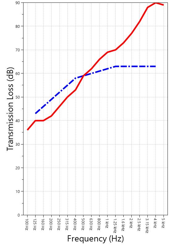
TRANSMISSION LOSS
SOUND TRANSMISSION CLASS CONTOUR
627 RIVERBANK DRIVE GENEVA, IL 60134
630-232-0104
University of Oregon RAL™-TL24-280 2024-06-25 Page 17 of 20
Specimen: Marmoleum Decibel adhered with Sustain 1195, 1-1/8” T&G plywood subfloor screwed 24” OC with #9x3", cavity filled with: 3” of 3/8" limestone chip and Hempitecture 3/4” hemp fiber board, 2x4 sleepers 24”OC with Rothoblaas Piano B acoustic strips stapled top/bottom, Vaagen Timbers 5-ply CLT 6.875” with plywood spline 3/4”x6” at the joint secured with #9x3” screws at 6” OC
The following non-accredited data were obtained in accordance with ASTM E90-09 (2016), but extend beyond the defined frequency range of 100Hz to 5,000Hz. These unofficial results are representative of the RAL test environment only and intended for research & comparison purposes. Sampling precision observed during this procedure is reported below. Corrections are detailed in Appendix B.
1/3 Octave Band Sound
627 RIVERBANK DRIVE GENEVA, IL 60134
630-232-0104
University of Oregon
2024-06-25 Page 18 of 20
Specimen: Marmoleum Decibel adhered with Sustain 1195, 1-1/8” T&G plywood subfloor screwed 24” OC with #9x3", cavity filled with: 3” of 3/8" limestone chip and Hempitecture 3/4” hemp fiber board, 2x4 sleepers 24”OC with Rothoblaas Piano B acoustic strips stapled top/bottom, Vaagen Timbers 5-ply CLT 6.875” with plywood spline 3/4”x6” at the joint secured with #9x3” screws at 6” OC (See Full Report)
Mark Interpretation
A Measured sound pressure levels in the receive room are within 10 dB of the ambient noise level at the marked frequency band. Receive room levels used to calculate Transmission Loss are corrected according to ASTM E90 Section 10.3.
AA Measured sound pressure levels in the receive room are within 5 dB of the ambient noise level at the marked frequency band. Receive room levels used to calculate Transmission Loss are corrected according to ASTM E90 Section 10.3.1. Transmission Loss values calculated from levels corrected this way will be less than or equal to Transmission Loss values from a hypothetical test using the same specimen and a receive room with idealized ambient sound levels of (-∞) dB.
F The reported Transmission Loss is within 10 dB of the laboratory flanking limit at the marked frequency band. The measured performance of the specimen may be limited by the performance of the laboratory building structure at this frequency band.
Z The reported Transmission Loss at the marked frequency band has been corrected according to ASTM E90 Section A3.2.7 to account for possible sound transmission through the filler assembly.
ZZ The reported Transmission Loss at the marked frequency band has been corrected according to ASTM E90 Section A3.2.8 to account for possible sound transmission through the filler assembly. Transmission Loss values corrected this way will be less than or equal to Transmission Loss values from a hypothetical test using the same specimen and an idealized filler assembly with a Sound Transmission Class rating of (∞).
Specimen: Marmoleum Decibel adhered with Sustain 1195, 1-1/8” T&G plywood subfloor screwed 24” OC with #9x3", cavity filled with: 3” of 3/8" limestone chip and Hempitecture 3/4” hemp fiber board, 2x4 sleepers 24”OC with Rothoblaas Piano B acoustic strips stapled top/bottom, Vaagen Timbers 5-ply CLT 6.875” with plywood spline 3/4”x6” at the joint secured with #9x3” screws at 6” OC (See Full Report)
ΔTL, the 95% confidence interval for reported transmission loss values, is calculated from the standard deviation of the sets of measurements for source room sound pressure level, receive room sound pressure level, and receive room sound absorption. This metric is calculated in an effort to quantify the combined influences of room geometry, microphone positioning, and other varying environmental conditions on reported results.
Repeatability, expressed as a 95% confidence interval, is calculated from the standard deviation of transmission loss as obtained from a set of six (6) consecutive tests conducted according to this test method by RAL from 202102-25 through 2021-03-04. The tests were performed on a specimen composed of a 6 in. thick concrete slab, using the same test opening as used in this report. This metric provides an estimate of the variation in results that might be observed if the test were repeated with no change to the installed specimen. Note that repeatability will vary with the construction type.
627 RIVERBANK DRIVE GENEVA, IL 60134 630-232-0104
University of Oregon RAL™-TL24-280 2024-06-25 Page 19 of 20
APPENDIX D: Determination of Outdoor Indoor Transmission Class (OITC)
Specimen: Marmoleum Decibel adhered with Sustain 1195, 1-1/8” T&G plywood subfloor screwed 24” OC with #9x3", cavity filled with: 3” of 3/8" limestone chip and Hempitecture 3/4” hemp fiber board, 2x4 sleepers 24”OC with Rothoblaas Piano B acoustic strips stapled top/bottom, Vaagen Timbers 5-ply CLT 6.875” with plywood spline 3/4”x6” at the joint secured with #9x3” screws at 6” OC (See Full Report)
The determination of the Outdoor Indoor Transmission Class (OITC) as reported below was made with explicit conformity to the procedures described in the ASTM E1332-22 test standard. Test Method ASTM E90-09 (2016) was used to obtain the sound transmission loss data. This rating is based on an average transportation noise source spectrum and an A-weighted sound level reduction, either of which may be inappropriate for some applications.
One-third Octave Band Center Frequency, Hz Reference Sound Spectrum, dB Test Specimen Transmission
627 RIVERBANK DRIVE GENEVA, IL 60134 630-232-0104
University of Oregon RAL™-TL24-280 2024-06-25 Page 20 of 20
APPENDIX E: Instruments of Traceability
Specimen: Marmoleum Decibel adhered with Sustain 1195, 1-1/8” T&G plywood subfloor screwed 24” OC with #9x3", cavity filled with: 3” of 3/8" limestone chip and Hempitecture 3/4” hemp fiber board, 2x4 sleepers 24”OC with Rothoblaas Piano B acoustic strips stapled top/bottom, Vaagen Timbers 5-ply CLT 6.875” with plywood spline 3/4”x6” at the joint secured with #9x3” screws at 6” OC (See Full Report)
Bruel & Kjaer Pistonphone Type 4228 2781248 2023-07-12 2024-07-12
EXTECH Hygro 663 SD700 A083663 2023-12-28 2024-12-28
EXTECH Hygro 639 SD700 A.103639 2023-12-01 2024-12-01
APPENDIX F: Revisions to Original Test Report
Specimen: Marmoleum Decibel adhered with Sustain 1195, 1-1/8” T&G plywood subfloor screwed 24” OC with #9x3", cavity filled with: 3” of 3/8" limestone chip and Hempitecture 3/4” hemp fiber board, 2x4 sleepers 24”OC with Rothoblaas Piano B acoustic strips stapled top/bottom, Vaagen Timbers 5-ply CLT 6.875” with plywood spline 3/4”x6” at the joint secured with #9x3” screws at 6” OC (See Full Report)
Original report issued
627 RIVERBANK DRIVE GENEVA, IL 60134 630-232-0104
WALLACE CLEMENT SABINE
SPONSOR: University of Oregon Sound Transmission Loss Portland, OR RAL™-TL24-281
CONDUCTED: 2024-06-26
Page 1 of 17
ON: 1-1/8” T&G plywood subfloor screwed 24” OC with #9x3”, cavity filled with: HempWool Acoustibatt 3.5” hemp batt, 2x4 sleepers 24”OC with Rothoblaas Piano B acoustic strips stapled top/bottom, Vaagen Timbers 5-ply CLT 6.875” with plywood spline 3/4”x6” at the joint secured with #9x3” screws at 6” OC
Riverbank Acoustical Laboratories™ is accredited by the U.S. Department of Commerce, National Institute of Standards and Technology (NIST) under the National Voluntary Laboratory Accreditation Program (NVLAP) as an ISO 17025:2017 Laboratory (NVLAP Lab Code: 100227-0) and for this test procedure. The test reported in this document conformed explicitly with ASTM E90-09 (2016): "Standard Test Method for Laboratory Measurement of Airborne Sound Transmission Loss of Building Partitions and Elements." The single number rating of the specimen was calculated according to ASTM E413-22: "Classification for Rating Sound Insulation." A description of the measurement procedure and room specifications is available upon request. The transmission loss values are for a single direction of measurement. The results presented in this report apply to the sample as received from the test sponsor.
INFORMATION PROVIDED BY SPONSOR
The test specimen was designated by the sponsor as 1-1/8” T&G plywood subfloor screwed 24” OC with #9x3”, cavity filled with: HempWool Acoustibatt 3.5” hemp batt, 2x4 sleepers 24”OC with Rothoblaas Piano B acoustic strips stapled top/bottom, Vaagen Timbers 5-ply CLT 6.875” with plywood spline 3/4”x6” at the joint secured with #9x3” screws at 6” OC. The following nominal product information was provided by the sponsor prior to testing. The accuracy of such sponsor-provided information can affect the validity of the test results.
Provided Description: 1-1/8” T&G plywood subfloor screwed 24” OC with #9x3", cavity filled with: HempWool Acoustibatt 3.5” hemp batt, 2x4 sleepers 24”OC with Rothoblaas Piano B acoustic strips stapled top/bottom, Vaagen Timbers 5-ply CLT 6.875” with plywood spline 3/4”x6” at the joint secured with #9x3” screws at 6” OC
Manufacturer: University of Oregon
627 RIVERBANK DRIVE GENEVA, IL 60134 630-232-0104
University of Oregon
2024-06-26
Page 2 of 17
The building contractor (Seth Priser) and RAL staff compiled a detailed construction specification as follows:
Cross-Laminated Timber (CLT)
Materials: 5-Ply Cross-Laminated Timber
Dimensions: 2 panels @ 1219 mm (48 in.) by 4229 mm (166.5 in.)
Thickness: 171 mm (6.75 in.)
Overall Weight: 953.45 kg (2102 lbs)
Mass Per Unit Volume: 539 kg/m3 (33.7 lbs/ft3)
Installation: CLT panels laid on 152 mm (6 in.) wide knee walls in test opening and butted to one another without sealant/adhesive.
3/4”x3” Rabbet on top side of one edge of each panel where they butt allowing a loose spline (below) to insert and join the two
¾” CDX Loose Spline
Materials: 3/4” x 6” plywood spline
Dimensions: 1 piece @ 151 mm (5.9375 in.) wide by 2438 mm (96 in.) 1 piece @ 151 mm (5.9375 in.) wide by 1791 mm (70.5 in.)
Thickness: 19 mm (0.75 in.)
Overall Weight: 6.46 kg (14.25 lbs)
Mass Per Unit Length: 1.53 kg/m (1.03 lbs/ft)
Installation: Set in Rabbets of both CLT’s and screwed in place.
Fasteners: WSV Bugle head sub-floor screws, length @ 76 mm (3 in.)
Fastener Spacing: 6” o.c. on a line 3” from each edge of the spline (Centered on the rabbet of the CLT)
Piano B 40/40 (Lower Layer)
Manufacturer: Rothoblaas
Dimensions: 2 strips @ 40 mm (1.5625 in.) wide by 4267 mm (168 in.) long 8 strips @ 2362 mm (93 in.) wide by 40 mm (1.5625 in.) long
Thickness: 6.76 mm (0.266 in.)
Overall Weight: 4.59 kg (10.125 lbs)
Mass Per Unit Volume: 624 kg/m3 (40.0 lbs/ft3)
Installation: Fastened to underside of 2” x 4” wood sleepers with staples
Fasteners: Arrow staples, length @ 13 mm (0.5 in.)
University of Oregon
2024-06-26
SPECIMEN MEASUREMENTS & TEST CONDITIONS (continued)
2” by 4” SPF Framing Sleepers
Materials: Nominal 2”x 4” framing lumber
Page 3 of 17
Dimensions: 2 pieces @ 38 mm (1.5 in.) wide by 4255 mm (167.5 in.) long
8 pieces @ 2369 mm (93.25 in.) wide by 38 mm (1.5 in.) long
Depth: 89 mm (3.5 in.)
Overall Weight: 49.33 kg (108.75 lbs)
Mass Per Unit Length: 1.80 kg/m (1.21 lbs/ft)
Installation: Sleepers laid over CLT, resting on lower layer Piano B 40/40
Longer sleepers parallel to CLT like a rim joist
Shorter sleepers set like floor joists between rim joists
Shorter sleepers spaced approx. 610 mm (24 in.) on center
Shorter sleepers fastened to longer sleepers with screws, 2 screws per connection point
Fasteners: WSV Bugle head sub-floor screws, length @ 76 mm (3 in.)
Piano B 40/40 (Upper Layer)
Manufacturer: Rothoblaas
Dimensions: 2 strips @ 40 mm (1.5625 in.) wide by 4267 mm (168 in.) long 8 strips @ 2362 mm (93 in.) wide by 40 mm (1.5625 in.) long
Thickness: 6.76 mm (0.266 in.)
Overall Weight: 4.59 kg (10.125 lbs)
Mass Per Unit Volume: 624 kg/m3 (40.0 lbs/ft3)
Installation: Fastened to top of 2” x 4” wood sleepers with staples
Fasteners: Arrow staples, length @ 13 mm (0.5 in.)
Materials: 3” Hemp fiber board
Manufacturer: Hempitecture
Dimensions: 7 pieces @ 572 mm (22.5 in.) wide by 2369 mm (93.25 in.) long
Depth: 76 mm (3 in.)
Overall Weight: 37.53 kg (82.75 lbs)
Mass Per Unit Volume: 52.0 kg/m3 (3.25 lbs/ft3)
Installation: Friction fit between sleepers and on top of CLT
630-232-0104
University of Oregon
2024-06-26
SPECIMEN MEASUREMENTS & TEST CONDITIONS (continued)
Plywood Subfloor
Materials: T&G Plywood
Dimensions: 1 piece @ 1219 mm (48 in.) wide by 1829 mm (72 in.)
1 piece @ 1219 mm (48 in.) wide by 2438 mm (96 in.)
1 piece @ 1219 mm (48 in.) wide by 1822 mm (71.75 in.)
1 piece @ 1219 mm (48 in.) wide by 2432 mm (95.75 in.)
Thickness: 29 mm (1.125 in.)
Overall Weight: 172.25 kg (379.75 lbs)
Mass Per Unit Volume: 580 kg/m3 (36.2 lbs/ft3)
Installation: Placed over upper layer Piano B 40/40 over sleepers
Fastened to sleepers through Piano B 40/40 with screws
Plywood piece joints staggered
Fasteners: WSV Bugle head sub-floor screws, length @ 76 mm (3 in.)
Fastener Spacing: 610 mm (24 in.) on center
Page 4 of 17
University of Oregon
2024-06-26 Page 5 of 17
SPECIMEN MEASUREMENTS & TEST CONDITIONS (continued)
Overall Specimen Measurements
Dimensions: 2.44 m (96.0 in) wide by 3.86 m (152.0 in) high
Thickness: 0.3 m (11.875 in)
Weight: 1228.21 kg (2707.75 lbs)
Overall Area: 9.414 m² (101.33 ft²)
Mass per Unit Area: 118.04 kg/m² (24.18 lbs/ft²)
Test Aperture
Opening Size: 4.27 m (14.0 ft) x 6.10 m (20.0 ft)
Filler Wall: Yes
Aperture Size: 2.44 m (96.0 in) wide by 3.86 m (152.0 in) high
Transmission Area: 9.414 m² (101.33 ft²)
Sealed: Entire periphery (both sides) with dense mastic
Test Environment
Source Room
Volume: 131.12 m³
Temperature: 22.8 °C ± 0.0 °C
Relative Humidity: 64.5 % ± 1.0 %
Receive Room
Volume: 81.44 m³
Temperature: 22.2 °C ± 0.0 °C
Relative Humidity: 64.0 % ± 0.0 %
Requirements
Temperature: 22º C +/- 2° C, not more than 3° C change over all tests.
Relative Humidity: ≥ 30%, not more than +/- 3% change over all tests.
University of Oregon
2024-06-26
Page 6 of 17
University of Oregon
2024-06-26
Page 7 of 17
University of Oregon
2024-06-26 Page 8 of 17
University of Oregon
2024-06-26 Page 9 of 17
University of Oregon
2024-06-26 Page 10 of 17
University of Oregon
2024-06-26 Page 11 of 17
University of Oregon
2024-06-26 Page 12 of 17
Sound transmission loss values are tabulated at the eighteen standard frequency bands. A graphic presentation of the data and additional information appear on the following pages. The precision of the transmission loss test data is within the limits set by the ASTM Standard E90-09 (2016). See Appendix A for identification of corrections applied to the reported data.
ABBREVIATION INDEX
FREQ. = 1/3 OCTAVE BAND CENTER FREQUENCY, Hz
TL = TRANSMISSION LOSS, dB
ΔTL = 95% CONFIDENCE INTERVAL FOR TL MEASUREMENTS, dB
DEF. = DEFICIENCIES, dB BELOW SHIFTED STC CONTOUR (SUM OF DEF = 30)
STC = SOUND TRANSMISSION CLASS Tested by_____________________________
Approved by
Eric P. Wolfram Laboratory Manager
627 RIVERBANK DRIVE
GENEVA, IL 60134
630-232-0104
University of Oregon
2024-06-26
Page 13 of 17
1-1/8” T&G plywood subfloor screwed 24” OC with #9x3”, cavity filled with: HempWool Acoustibatt 3.5” hemp batt, 2x4 sleepers 24”OC with Rothoblaas Piano B acoustic strips stapled top/bottom, Vaagen Timbers 5-ply CLT 6.875” with plywood spline 3/4”x6” at the joint secured with #9x3” screws at 6” OC
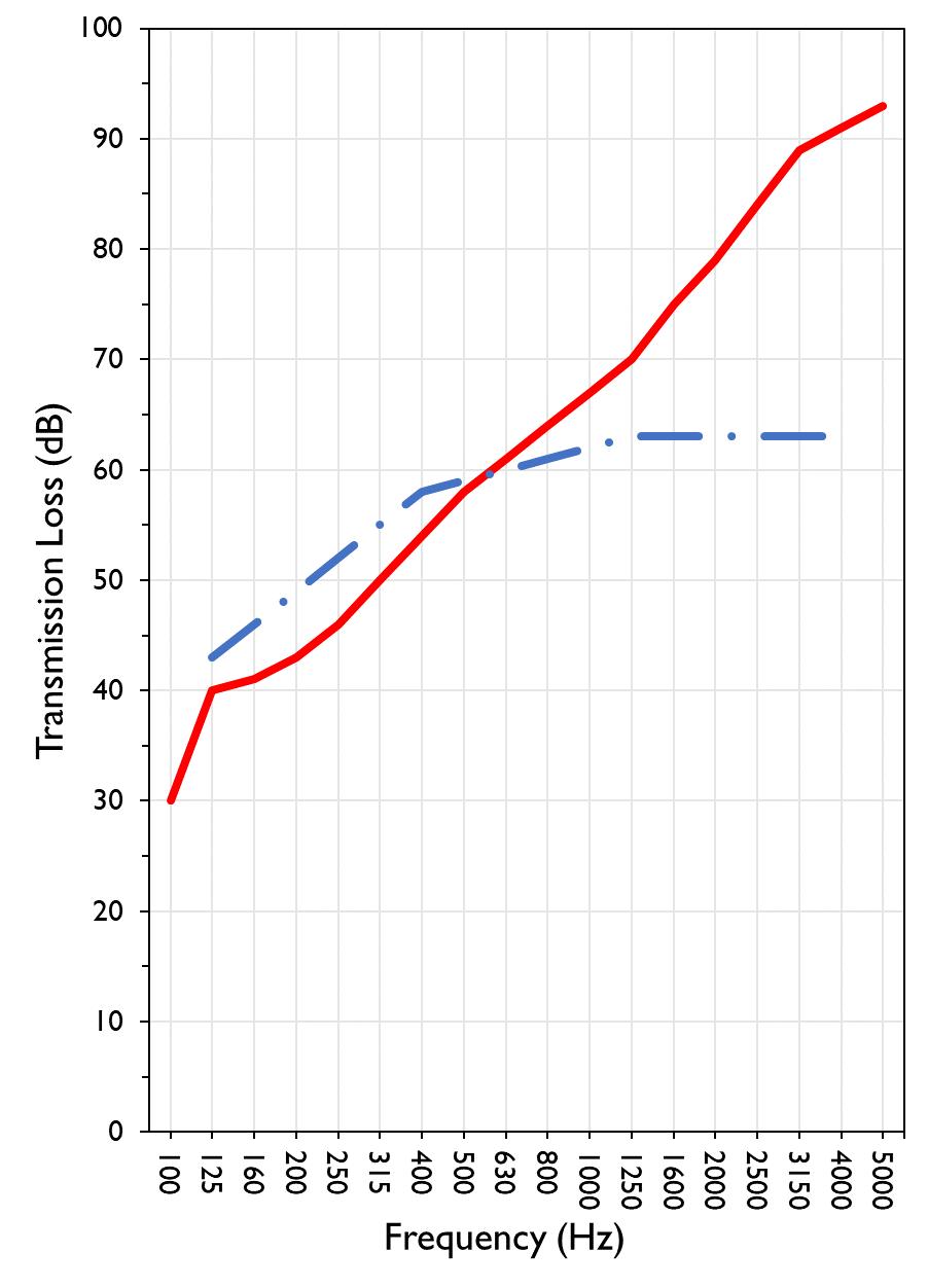
627 RIVERBANK DRIVE GENEVA, IL 60134
630-232-0104
University of Oregon
2024-06-26
Page 14 of 17
Specimen: 1-1/8” T&G plywood subfloor screwed 24” OC with #9x3”, cavity filled with: HempWool Acoustibatt 3.5” hemp batt, 2x4 sleepers 24”OC with Rothoblaas Piano B acoustic strips stapled top/bottom, Vaagen Timbers 5-ply CLT 6.875” with plywood spline 3/4”x6” at the joint secured with #9x3” screws at 6” OC
(See Full Report)
The following non-accredited data were obtained in accordance with ASTM E90-09 (2016), but extend beyond the defined frequency range of 100Hz to 5,000Hz. These unofficial results are representative of the RAL test environment only and intended for research & comparison purposes. Sampling precision observed during this procedure is reported below. Corrections are detailed in Appendix B.
1/3 Octave Band Sound
627 RIVERBANK DRIVE GENEVA, IL 60134
630-232-0104
University of Oregon
2024-06-26
Page 15 of 17
Specimen: 1-1/8” T&G plywood subfloor screwed 24” OC with #9x3”, cavity filled with: HempWool Acoustibatt 3.5” hemp batt, 2x4 sleepers 24”OC with Rothoblaas Piano B acoustic strips stapled top/bottom, Vaagen Timbers 5-ply CLT 6.875” with plywood spline 3/4”x6” at the joint secured with #9x3” screws at 6” OC (See Full Report)
Mark Interpretation
A Measured sound pressure levels in the receive room are within 10 dB of the ambient noise level at the marked frequency band. Receive room levels used to calculate Transmission Loss are corrected according to ASTM E90 Section 10.3.
AA Measured sound pressure levels in the receive room are within 5 dB of the ambient noise level at the marked frequency band. Receive room levels used to calculate Transmission Loss are corrected according to ASTM E90 Section 10.3.1. Transmission Loss values calculated from levels corrected this way will be less than or equal to Transmission Loss values from a hypothetical test using the same specimen and a receive room with idealized ambient sound levels of (-∞) dB.
F The reported Transmission Loss is within 10 dB of the laboratory flanking limit at the marked frequency band. The measured performance of the specimen may be limited by the performance of the laboratory building structure at this frequency band.
Z The reported Transmission Loss at the marked frequency band has been corrected according to ASTM E90 Section A3.2.7 to account for possible sound transmission through the filler assembly.
ZZ The reported Transmission Loss at the marked frequency band has been corrected according to ASTM E90 Section A3.2.8 to account for possible sound transmission through the filler assembly. Transmission Loss values corrected this way will be less than or equal to Transmission Loss values from a hypothetical test using the same specimen and an idealized filler assembly with a Sound Transmission Class rating of (∞).
Specimen: 1-1/8” T&G plywood subfloor screwed 24” OC with #9x3”, cavity filled with: HempWool Acoustibatt 3.5” hemp batt, 2x4 sleepers 24”OC with Rothoblaas Piano B acoustic strips stapled top/bottom, Vaagen Timbers 5-ply CLT 6.875” with plywood spline 3/4”x6” at the joint secured with #9x3” screws at 6” OC (See Full Report)
ΔTL, the 95% confidence interval for reported transmission loss values, is calculated from the standard deviation of the sets of measurements for source room sound pressure level, receive room sound pressure level, and receive room sound absorption. This metric is calculated in an effort to quantify the combined influences of room geometry, microphone positioning, and other varying environmental conditions on reported results.
Repeatability, expressed as a 95% confidence interval, is calculated from the standard deviation of transmission loss as obtained from a set of six (6) consecutive tests conducted according to this test method by RAL from 202102-25 through 2021-03-04. The tests were performed on a specimen composed of a 6 in. thick concrete slab, using the same test opening as used in this report. This metric provides an estimate of the variation in results that might be observed if the test were repeated with no change to the installed specimen. Note that repeatability will vary with the construction type.
627 RIVERBANK DRIVE GENEVA, IL 60134
630-232-0104
University of Oregon RAL™-TL24-281 2024-06-26 Page 16 of 17
APPENDIX D: Determination of Outdoor Indoor Transmission Class (OITC)
Specimen: 1-1/8” T&G plywood subfloor screwed 24” OC with #9x3”, cavity filled with: HempWool Acoustibatt 3.5” hemp batt, 2x4 sleepers 24”OC with Rothoblaas Piano B acoustic strips stapled top/bottom, Vaagen Timbers 5-ply CLT 6.875” with plywood spline 3/4”x6” at the joint secured with #9x3” screws at 6” OC (See Full Report)
The determination of the Outdoor Indoor Transmission Class (OITC) as reported below was made with explicit conformity to the procedures described in the ASTM E1332-22 test standard. Test Method ASTM E90-09 (2016) was used to obtain the sound transmission loss data. This rating is based on an average transportation noise source spectrum and an A-weighted sound level reduction, either of which may be inappropriate for some applications.
One-third Octave Band Center Frequency, Hz Reference Sound Spectrum, dB Test Specimen Transmission Loss, dB
= 44
627 RIVERBANK DRIVE GENEVA, IL 60134 630-232-0104
University of Oregon
2024-06-26 Page 17 of 17
Specimen: 1-1/8” T&G plywood subfloor screwed 24” OC with #9x3”, cavity filled with: HempWool
Acoustibatt 3.5” hemp batt, 2x4 sleepers 24”OC with Rothoblaas Piano B acoustic strips stapled top/bottom, Vaagen Timbers 5-ply CLT 6.875” with plywood spline 3/4”x6” at the joint secured with #9x3” screws at 6” OC (See Full Report)
System 2 Type 3160-A-042 3160106974 2023-08-11 2024-08-11
Bruel & Kjaer Mic And Preamp C Type 4943-B-001 2311439 2024-03-29 2025-03-29
Bruel & Kjaer Pistonphone Type 4228 2781248 2023-07-12 2024-07-12
EXTECH Hygro 663 SD700 A083663 2023-12-28 2024-12-28
EXTECH Hygro 639 SD700 A.103639 2023-12-01 2024-12-01
APPENDIX F: Revisions to Original Test Report
Specimen: 1-1/8” T&G plywood subfloor screwed 24” OC with #9x3”, cavity filled with: HempWool
Acoustibatt 3.5” hemp batt, 2x4 sleepers 24”OC with Rothoblaas Piano B acoustic strips stapled top/bottom, Vaagen Timbers 5-ply CLT 6.875” with plywood spline 3/4”x6” at the joint secured with #9x3” screws at 6” OC (See Full Report)
Date Revision 2024-07-31 Original report issued
627 RIVERBANK DRIVE
GENEVA, IL 60134
630-232-0104
SPONSOR: University of Oregon Sound Transmission Loss Portland, OR RAL™-TL24-294
CONDUCTED: 2024-06-28 Page 1 of 18 ON: Marmoleum Decibel adhered with Sustain 1195, 1-1/8” T&G plywood subfloor screwed 24” OC with #9x3", cavity filled with: HempWool Acoustibatt 3.5” hemp batt, 2x4 sleepers 24”OC with Rothoblaas Piano B acoustic strips stapled top/bottom, Vaagen Timbers 5-ply CLT 6.875” with plywood spline 3/4”x6” at the joint secured with #9x3” screws at 6” OC
Riverbank Acoustical Laboratories™ is accredited by the U.S. Department of Commerce, National Institute of Standards and Technology (NIST) under the National Voluntary Laboratory Accreditation Program (NVLAP) as an ISO 17025:2017 Laboratory (NVLAP Lab Code: 100227-0) and for this test procedure. The test reported in this document conformed explicitly with ASTM E90-09 (2016): "Standard Test Method for Laboratory Measurement of Airborne Sound Transmission Loss of Building Partitions and Elements." The single number rating of the specimen was calculated according to ASTM E413-22: "Classification for Rating Sound Insulation." A description of the measurement procedure and room specifications is available upon request. The transmission loss values are for a single direction of measurement. The results presented in this report apply to the sample as received from the test sponsor.
The test specimen was designated by the sponsor as Marmoleum Decibel adhered with Sustain 1195, 11/8” T&G plywood subfloor screwed 24” OC with #9x3", cavity filled with: HempWool Acoustibatt 3.5” hemp batt, 2x4 sleepers 24”OC with Rothoblaas Piano B acoustic strips stapled top/bottom, Vaagen Timbers 5-ply CLT 6.875” with plywood spline 3/4”x6” at the joint secured with #9x3” screws at 6” OC. The following nominal product information was provided by the sponsor prior to testing. The accuracy of such sponsor-provided information can affect the validity of the test results.
Provided Description: Marmoleum Decibel adhered with Sustain 1195, 1-1/8” T&G plywood subfloor screwed 24” OC with #9x3", cavity filled with: HempWool Acoustibatt 3.5” hemp batt, 2x4 sleepers 24”OC with Rothoblaas Piano B acoustic strips stapled top/bottom, Vaagen Timbers 5-ply CLT 6.875” with plywood spline 3/4”x6” at the joint secured with #9x3” screws at 6” OC
Manufacturer: University of Oregon
627 RIVERBANK DRIVE GENEVA, IL 60134 630-232-0104
University of Oregon
2024-06-28 Page 2 of 18
The building contractor (Seth Priser) and RAL staff compiled a detailed construction specification as follows:
Cross-Laminated Timber (CLT)
Materials: 5-Ply Cross-Laminated Timber
Dimensions: 2 panels @ 1219 mm (48 in.) by 4229 mm (166.5 in.)
Thickness: 171 mm (6.75 in.)
Overall Weight: 953.45 kg (2102 lbs)
Mass Per Unit Volume: 539 kg/m3 (33.7 lbs/ft3)
Installation: CLT panels laid on 152 mm (6 in.) wide knee walls in test opening and butted to one another without sealant/adhesive.
3/4”x3” Rabbet on top side of one edge of each panel where they butt allowing a loose spline (below) to insert and join the two
¾” CDX Loose Spline
Materials: 3/4” x 6” plywood spline
Dimensions: 1 piece @ 151 mm (5.9375 in.) wide by 2438 mm (96 in.) 1 piece @ 151 mm (5.9375 in.) wide by 1791 mm (70.5 in.)
Thickness: 19 mm (0.75 in.)
Overall Weight: 6.46 kg (14.25 lbs)
Mass Per Unit Length: 1.53 kg/m (1.03 lbs/ft)
Installation: Set in Rabbets of both CLT’s and screwed in place.
Fasteners: WSV Bugle head sub-floor screws, length @ 76 mm (3 in.)
Fastener Spacing: 6” o.c. on a line 3” from each edge of the spline (Centered on the rabbet of the CLT)
Piano B 40/40 (Lower Layer)
Manufacturer: Rothoblaas
Dimensions: 2 strips @ 40 mm (1.5625 in.) wide by 4267 mm (168 in.) long 8 strips @ 2362 mm (93 in.) wide by 40 mm (1.5625 in.) long
Thickness: 6.76 mm (0.266 in.)
Overall Weight: 4.59 kg (10.125 lbs)
Mass Per Unit Volume: 624 kg/m3 (40.0 lbs/ft3)
Installation: Fastened to underside of 2” x 4” wood sleepers with staples
Fasteners: Arrow staples, length @ 13 mm (0.5 in.)
University of Oregon
2024-06-28
SPECIMEN MEASUREMENTS & TEST CONDITIONS (continued)
2” by 4” SPF Framing Sleepers
Materials: Nominal 2”x 4” framing lumber
Page 3 of 18
Dimensions: 2 pieces @ 38 mm (1.5 in.) wide by 4255 mm (167.5 in.) long
8 pieces @ 2369 mm (93.25 in.) wide by 38 mm (1.5 in.) long
Depth: 89 mm (3.5 in.)
Overall Weight: 49.33 kg (108.75 lbs)
Mass Per Unit Length: 1.80 kg/m (1.21 lbs/ft)
Installation: Sleepers laid over CLT, resting on lower layer Piano B 40/40
Longer sleepers parallel to CLT like a rim joist
Shorter sleepers set like floor joists between rim joists
Shorter sleepers spaced approx. 610 mm (24 in.) on center
Shorter sleepers fastened to longer sleepers with screws, 2 screws per connection point
Fasteners: WSV Bugle head sub-floor screws, length @ 76 mm (3 in.)
Piano B 40/40 (Upper Layer)
Manufacturer: Rothoblaas
Dimensions: 2 strips @ 40 mm (1.5625 in.) wide by 4267 mm (168 in.) long 8 strips @ 2362 mm (93 in.) wide by 40 mm (1.5625 in.) long
Thickness: 6.76 mm (0.266 in.)
Overall Weight: 4.59 kg (10.125 lbs)
Mass Per Unit Volume: 624 kg/m3 (40.0 lbs/ft3)
Installation: Fastened to top of 2” x 4” wood sleepers with staples
Fasteners: Arrow staples, length @ 13 mm (0.5 in.)
Materials: 3” Hemp fiber board
Manufacturer: Hempitecture
Dimensions: 7 pieces @ 572 mm (22.5 in.) wide by 2369 mm (93.25 in.) long
Depth: 76 mm (3 in.)
Overall Weight: 37.53 kg (82.75 lbs)
Mass Per Unit Volume: 52.0 kg/m3 (3.25 lbs/ft3)
Installation: Friction fit between sleepers and on top of CLT
630-232-0104
University of Oregon
2024-06-28
SPECIMEN MEASUREMENTS & TEST CONDITIONS (continued)
Plywood Subfloor
Materials: T&G Plywood
Dimensions: 1 piece @ 1219 mm (48 in.) wide by 1829 mm (72 in.)
1 piece @ 1219 mm (48 in.) wide by 2438 mm (96 in.)
1 piece @ 1219 mm (48 in.) wide by 1822 mm (71.75 in.)
1 piece @ 1219 mm (48 in.) wide by 2432 mm (95.75 in.)
Thickness: 29 mm (1.125 in.)
Overall Weight: 172.25 kg (379.75 lbs)
Mass Per Unit Volume: 580 kg/m3 (36.2 lbs/ft3)
Installation: Placed over upper layer Piano B 40/40 over sleepers
Fastened to sleepers through Piano B 40/40 with screws
Plywood piece joints staggered
Fasteners: WSV Bugle head sub-floor screws, length @ 76 mm (3 in.)
Fastener Spacing: 610 mm (24 in.) on center
Adhesive
Materials: Sustain 1195 Sheet and Tile adhesive
Manufacturer: Forbo
Dimensions: Approx. 2438 mm (96 in.) by 4267 mm (168 in.) as installed
Overall Weight: 4.2 kg (9.25 lbs)
Mass Per Unit Area: 0.40 kg/m2 (0.08 lbs/ft2)
Flooring
Page 4 of 18
Installation: Troweled directly to plywood with a 1/16x1/16x1/16 square notch trowel Once troweled, adhesive was left “open” for 15 min to allow it to “tack” before flooring was installed.
Materials: Marmoleum Decibel
Manufacturer: Forbo
Dimensions: 2 pieces @ 2007 mm (79 in.) by 2464 mm (97 in.)
1 piece @ 257 mm (10.125 in.) by 2438 mm (96 in.)
Thickness: 6 mm (0.25 in.)
Overall Weight: 32.32 kg (71.25 lbs)
Mass Per Unit Volume: 484 kg/m3 (30.2 lbs/ft3)
Installation: Two (2) 79” segments perpendicular to Plywood 10” strip to complete Joints staggered from parallel plywood joints by + 6” Rolled with 100lb roller in each direction
University of Oregon
2024-06-28 Page 5 of 18
SPECIMEN MEASUREMENTS & TEST CONDITIONS (continued)
Overall Specimen Measurements
Dimensions: 2.44 m (96.0 in) wide by 3.86 m (152.0 in) high
Thickness: 0.31 m (12.125 in)
Weight: 1264.73 kg (2788.25 lbs)
Overall Area: 9.414 m² (101.33 ft²)
Mass per Unit Area: 121.55 kg/m² (24.90 lbs/ft²)
Test Aperture
Opening Size: 4.27 m (14.0 ft) x 6.10 m (20.0 ft)
Filler Wall: Yes
Aperture Size: 2.44 m (96.0 in) wide by 3.86 m (152.0 in) high
Transmission Area: 9.414 m² (101.33 ft²)
Sealed: Entire periphery (both sides) with dense mastic
Test Environment
Source Room
Volume: 131.12 m³
Temperature: 23.3 °C ± 0.0 °C
Relative Humidity: 60.0 % ± 0.0 %
Receive Room
Volume: 81.44 m³
Temperature: 22.2 °C ± 0.0 °C
Relative Humidity: 62.0 % ± 0.0 %
Requirements
Temperature: 22º C +/- 2° C, not more than 3° C change over all tests.
Relative Humidity: ≥ 30%, not more than +/- 3% change over all tests.
University of Oregon
2024-06-28 Page 6 of 18
University of Oregon
2024-06-28
Page 7 of 18
University of Oregon
2024-06-28 Page 8 of 18
University of Oregon
2024-06-28 Page 9 of 18
University of Oregon
2024-06-28 Page 10 of 18
University of Oregon
2024-06-28 Page 11 of 18
University of Oregon
2024-06-28 Page 12 of 18
University of Oregon
2024-06-28 Page 13 of 18
Sound transmission loss values are tabulated at the eighteen standard frequency bands. A graphic presentation of the data and additional information appear on the following pages. The precision of the transmission loss test data is within the limits set by the ASTM Standard E90-09 (2016). See Appendix A for identification of corrections applied to the reported data.
ABBREVIATION INDEX
FREQ. = 1/3 OCTAVE BAND CENTER FREQUENCY, Hz
TL = TRANSMISSION LOSS, dB
ΔTL = 95% CONFIDENCE INTERVAL FOR TL MEASUREMENTS, dB
DEF. = DEFICIENCIES, dB BELOW SHIFTED STC CONTOUR (SUM OF DEF = 31)
STC = SOUND TRANSMISSION CLASS
Keith Kimberling Senior Experimentalist Test Engineer
Tested by_____________________________ Report by__________________________
Approved by _______________________
Eric P. Wolfram Laboratory Manager
627 RIVERBANK DRIVE
GENEVA, IL 60134
630-232-0104
University of Oregon
2024-06-28 Page 14 of 18
Marmoleum Decibel adhered with Sustain 1195, 1-1/8” T&G plywood subfloor screwed 24” OC with #9x3", cavity filled with: HempWool Acoustibatt 3.5” hemp batt, 2x4 sleepers 24”OC with Rothoblaas Piano B acoustic strips stapled top/bottom, Vaagen Timbers 5-ply CLT 6.875” with plywood spline 3/4”x6” at the joint secured with #9x3” screws at 6” OC
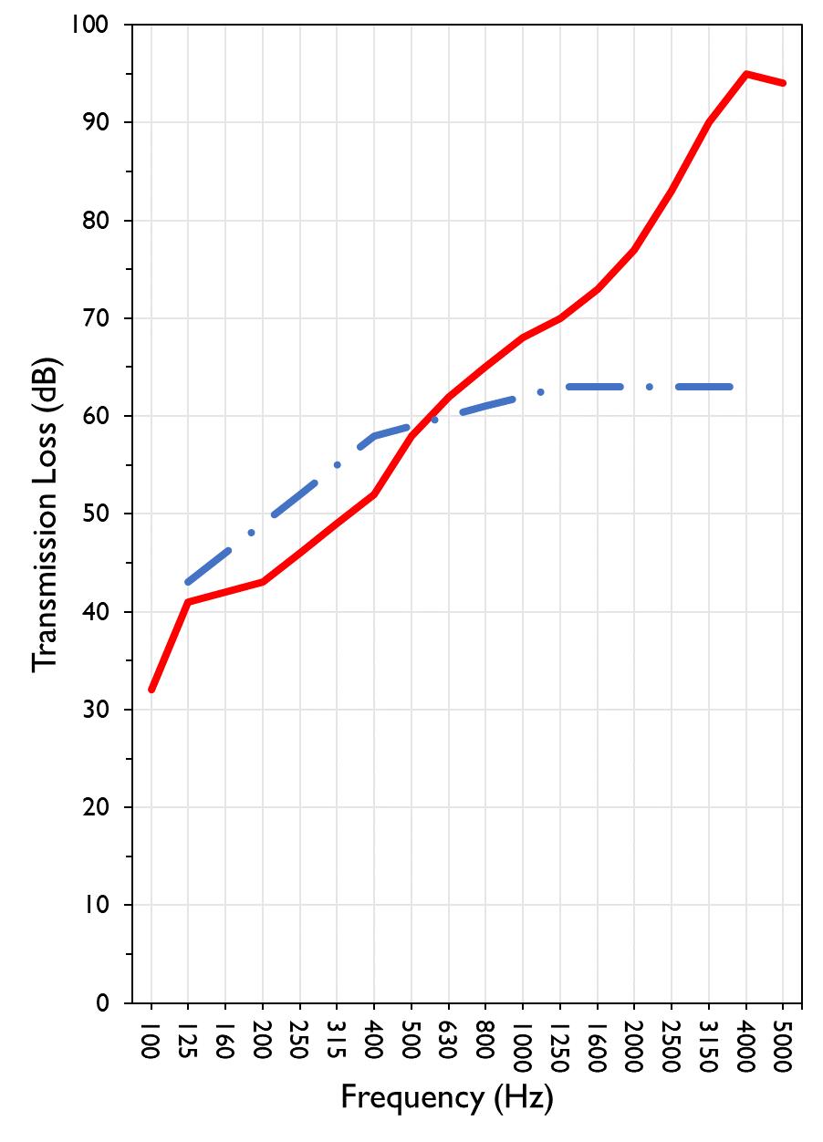
627 RIVERBANK DRIVE GENEVA, IL 60134
630-232-0104
University of Oregon RAL™-TL24-294 2024-06-28 Page 15 of 18
Specimen: Marmoleum Decibel adhered with Sustain 1195, 1-1/8” T&G plywood subfloor screwed 24” OC with #9x3", cavity filled with: HempWool Acoustibatt 3.5” hemp batt, 2x4 sleepers 24”OC with Rothoblaas Piano B acoustic strips stapled top/bottom, Vaagen Timbers 5-ply CLT 6.875” with plywood spline 3/4”x6” at the joint secured with #9x3” screws at 6” OC (See Full Report)
The following non-accredited data were obtained in accordance with ASTM E90-09 (2016), but extend beyond the defined frequency range of 100Hz to 5,000Hz. These unofficial results are representative of the RAL test environment only and intended for research & comparison purposes. Sampling precision observed during this procedure is reported below. Corrections are detailed in Appendix B.
1/3 Octave Band Sound
627 RIVERBANK DRIVE GENEVA, IL 60134
630-232-0104
University of Oregon
2024-06-28 Page 16 of 18
Specimen: Marmoleum Decibel adhered with Sustain 1195, 1-1/8” T&G plywood subfloor screwed 24” OC with #9x3", cavity filled with: HempWool Acoustibatt 3.5” hemp batt, 2x4 sleepers 24”OC with Rothoblaas Piano B acoustic strips stapled top/bottom, Vaagen Timbers 5-ply CLT 6.875” with plywood spline 3/4”x6” at the joint secured with #9x3” screws at 6” OC (See Full Report)
Mark Interpretation
A Measured sound pressure levels in the receive room are within 10 dB of the ambient noise level at the marked frequency band. Receive room levels used to calculate Transmission Loss are corrected according to ASTM E90 Section 10.3.
AA Measured sound pressure levels in the receive room are within 5 dB of the ambient noise level at the marked frequency band. Receive room levels used to calculate Transmission Loss are corrected according to ASTM E90 Section 10.3.1. Transmission Loss values calculated from levels corrected this way will be less than or equal to Transmission Loss values from a hypothetical test using the same specimen and a receive room with idealized ambient sound levels of (-∞) dB.
F The reported Transmission Loss is within 10 dB of the laboratory flanking limit at the marked frequency band. The measured performance of the specimen may be limited by the performance of the laboratory building structure at this frequency band.
Z The reported Transmission Loss at the marked frequency band has been corrected according to ASTM E90 Section A3.2.7 to account for possible sound transmission through the filler assembly.
ZZ The reported Transmission Loss at the marked frequency band has been corrected according to ASTM E90 Section A3.2.8 to account for possible sound transmission through the filler assembly. Transmission Loss values corrected this way will be less than or equal to Transmission Loss values from a hypothetical test using the same specimen and an idealized filler assembly with a Sound Transmission Class rating of (∞).
Specimen: Marmoleum Decibel adhered with Sustain 1195, 1-1/8” T&G plywood subfloor screwed 24” OC with #9x3", cavity filled with: HempWool Acoustibatt 3.5” hemp batt, 2x4 sleepers 24”OC with Rothoblaas Piano B acoustic strips stapled top/bottom, Vaagen Timbers 5-ply CLT 6.875” with plywood spline 3/4”x6” at the joint secured with #9x3” screws at 6” OC (See Full Report)
ΔTL, the 95% confidence interval for reported transmission loss values, is calculated from the standard deviation of the sets of measurements for source room sound pressure level, receive room sound pressure level, and receive room sound absorption. This metric is calculated in an effort to quantify the combined influences of room geometry, microphone positioning, and other varying environmental conditions on reported results.
Repeatability, expressed as a 95% confidence interval, is calculated from the standard deviation of transmission loss as obtained from a set of six (6) consecutive tests conducted according to this test method by RAL from 202102-25 through 2021-03-04. The tests were performed on a specimen composed of a 6 in. thick concrete slab, using the same test opening as used in this report. This metric provides an estimate of the variation in results that might be observed if the test were repeated with no change to the installed specimen. Note that repeatability will vary with the construction type.
627 RIVERBANK DRIVE GENEVA, IL 60134
630-232-0104
1918 BY WALLACE CLEMENT SABINE
University of Oregon RAL™-TL24-294 2024-06-28 Page 17 of 18
APPENDIX D: Determination of Outdoor Indoor Transmission Class (OITC)
Specimen: Marmoleum Decibel adhered with Sustain 1195, 1-1/8” T&G plywood subfloor screwed 24” OC with #9x3", cavity filled with: HempWool Acoustibatt 3.5” hemp batt, 2x4 sleepers 24”OC with Rothoblaas Piano B acoustic strips stapled top/bottom, Vaagen Timbers 5-ply CLT 6.875” with plywood spline 3/4”x6” at the joint secured with #9x3” screws at 6” OC (See Full Report)
The determination of the Outdoor Indoor Transmission Class (OITC) as reported below was made with explicit conformity to the procedures described in the ASTM E1332-22 test standard. Test Method ASTM E90-09 (2016) was used to obtain the sound transmission loss data. This rating is based on an average transportation noise source spectrum and an A-weighted sound level reduction, either of which may be inappropriate for some applications.
One-third Octave Band Center Frequency, Hz Reference Sound Spectrum, dB Test Specimen
1918 BY WALLACE CLEMENT SABINE 627 RIVERBANK DRIVE GENEVA, IL 60134 630-232-0104
University of Oregon RAL™-TL24-294 2024-06-28 Page 18 of 18
APPENDIX E: Instruments of Traceability
Specimen: Marmoleum Decibel adhered with Sustain 1195, 1-1/8” T&G plywood subfloor screwed 24” OC with #9x3", cavity filled with: HempWool Acoustibatt 3.5” hemp batt, 2x4 sleepers 24”OC with Rothoblaas Piano B acoustic strips stapled top/bottom, Vaagen Timbers 5-ply CLT 6.875” with plywood spline 3/4”x6” at the joint secured with #9x3” screws at 6” OC (See Full Report)
System 2 Type 3160-A-042 3160106974 2023-08-11 2024-08-11
Bruel & Kjaer Mic And Preamp C Type 4943-B-001 2311439 2024-03-29 2025-03-29
Bruel & Kjaer Pistonphone Type 4228 2781248 2023-07-12 2024-07-12
EXTECH Hygro 663 SD700 A083663 2023-12-28 2024-12-28
EXTECH Hygro 639 SD700 A.103639 2023-12-01 2024-12-01
APPENDIX F: Revisions to Original Test Report
Specimen: Marmoleum Decibel adhered with Sustain 1195, 1-1/8” T&G plywood subfloor screwed 24” OC with #9x3", cavity filled with: HempWool Acoustibatt 3.5” hemp batt, 2x4 sleepers 24”OC with Rothoblaas Piano B acoustic strips stapled top/bottom, Vaagen Timbers 5-ply CLT 6.875” with plywood spline 3/4”x6” at the joint secured with #9x3” screws at 6” OC (See Full Report) Date
2024-07-31 Original report issued
627 RIVERBANK DRIVE
GENEVA, IL 60134
630-232-0104
SPONSOR: University of Oregon Sound Transmission Loss Portland, OR RAL™-TL24-302
CONDUCTED: 2024-07-08
Page 1 of 18
ON: 1” Maxxon gypcrete 2000 Multifamily, 1-1/8” T&G plywood subfloor screwed 24” OC with #9x3”, cavity filled with: HempWool Acoustibatt 3.5” hemp batt, 2x4 sleepers 24”OC with Rothoblaas Piano B acoustic strips stapled top/bottom, Vaagen Timbers 5-ply CLT 6.875” with plywood spline 3/4”x6” at the joint secured with #9x3” screws at 6” OC
Riverbank Acoustical Laboratories™ is accredited by the U.S. Department of Commerce, National Institute of Standards and Technology (NIST) under the National Voluntary Laboratory Accreditation Program (NVLAP) as an ISO 17025:2017 Laboratory (NVLAP Lab Code: 100227-0) and for this test procedure. The test reported in this document conformed explicitly with ASTM E90-09 (2016): "Standard Test Method for Laboratory Measurement of Airborne Sound Transmission Loss of Building Partitions and Elements." The single number rating of the specimen was calculated according to ASTM E413-22: "Classification for Rating Sound Insulation." A description of the measurement procedure and room specifications is available upon request. The transmission loss values are for a single direction of measurement. The results presented in this report apply to the sample as received from the test sponsor.
The test specimen was designated by the sponsor as 1” Maxxon gypcrete 2000 Multifamily, 1-1/8” T&G plywood subfloor screwed 24” OC with #9x3”, cavity filled with: HempWool Acoustibatt 3.5” hemp batt, 2x4 sleepers 24”OC with Rothoblaas Piano B acoustic strips stapled top/bottom, Vaagen Timbers 5-ply CLT 6.875” with plywood spline 3/4”x6” at the joint secured with #9x3” screws at 6” OC. The following nominal product information was provided by the sponsor prior to testing. The accuracy of such sponsorprovided information can affect the validity of the test results.
Provided Description: 1” Maxxon gypcrete 2000 Multifamily, 1-1/8” T&G plywood subfloor screwed 24” OC with #9x3", cavity filled with: HempWool Acoustibatt 3.5” hemp batt, 2x4 sleepers 24”OC with Rothoblaas Piano B acoustic strips stapled top/bottom, Vaagen Timbers 5-ply CLT 6.875” with plywood spline 3/4”x6” at the joint secured with #9x3” screws at 6” OC
Manufacturer: University of Oregon
627 RIVERBANK DRIVE GENEVA, IL 60134 630-232-0104
University of Oregon
2024-07-08 Page 2 of 18
The building contractor (Seth Priser) and RAL staff compiled a detailed construction specification as follows:
Cross-Laminated Timber (CLT)
Materials: 5-Ply Cross-Laminated Timber
Dimensions: 2 panels @ 1219 mm (48 in.) by 4229 mm (166.5 in.)
Thickness: 171 mm (6.75 in.)
Overall Weight: 953.45 kg (2102 lbs)
Mass Per Unit Volume: 539 kg/m3 (33.7 lbs/ft3)
Installation: CLT panels laid on 152 mm (6 in.) wide knee walls in test opening and butted to one another without sealant/adhesive.
3/4”x3” Rabbet on top side of one edge of each panel where they butt allowing a loose spline (below) to insert and join the two
¾” CDX Loose Spline
Materials: 3/4” x 6” plywood spline
Dimensions: 1 piece @ 151 mm (5.9375 in.) wide by 2438 mm (96 in.) 1 piece @ 151 mm (5.9375 in.) wide by 1791 mm (70.5 in.)
Thickness: 19 mm (0.75 in.)
Overall Weight: 6.46 kg (14.25 lbs)
Mass Per Unit Length: 1.53 kg/m (1.03 lbs/ft)
Installation: Set in Rabbets of both CLT’s and screwed in place.
Fasteners: WSV Bugle head sub-floor screws, length @ 76 mm (3 in.)
Fastener Spacing: 6” o.c. on a line 3” from each edge of the spline (Centered on the rabbet of the CLT)
Piano B 40/40 (Lower Layer)
Manufacturer: Rothoblaas
Dimensions: 2 strips @ 40 mm (1.5625 in.) wide by 4267 mm (168 in.) long 8 strips @ 2362 mm (93 in.) wide by 40 mm (1.5625 in.) long
Thickness: 6.76 mm (0.266 in.)
Overall Weight: 4.59 kg (10.125 lbs)
Mass Per Unit Volume: 624 kg/m3 (40.0 lbs/ft3)
Installation: Fastened to underside of 2” x 4” wood sleepers with staples
Fasteners: Arrow staples, length @ 13 mm (0.5 in.)
University of Oregon
2024-07-08 Page 3 of 18
SPECIMEN MEASUREMENTS & TEST CONDITIONS (continued)
2” by 4” SPF Framing Sleepers
Materials: Nominal 2”x 4” framing lumber
Dimensions: 2 pieces @ 38 mm (1.5 in.) wide by 4255 mm (167.5 in.) long
8 pieces @ 2369 mm (93.25 in.) wide by 38 mm (1.5 in.) long
Depth: 89 mm (3.5 in.)
Overall Weight: 49.33 kg (108.75 lbs)
Mass Per Unit Length: 1.80 kg/m (1.21 lbs/ft)
Installation: Sleepers laid over CLT, resting on lower layer Piano B 40/40
Longer sleepers parallel to CLT like a rim joist
Shorter sleepers set like floor joists between rim joists
Shorter sleepers spaced approx. 610 mm (24 in.) on center
Shorter sleepers fastened to longer sleepers with screws, 2 screws per connection point
Fasteners: WSV Bugle head sub-floor screws, length @ 76 mm (3 in.)
Piano B 40/40 (Upper Layer)
Manufacturer: Rothoblaas
Dimensions: 2 strips @ 40 mm (1.5625 in.) wide by 4267 mm (168 in.) long 8 strips @ 2362 mm (93 in.) wide by 40 mm (1.5625 in.) long
Thickness: 6.76 mm (0.266 in.)
Overall Weight: 4.59 kg (10.125 lbs)
Mass Per Unit Volume: 624 kg/m3 (40.0 lbs/ft3)
Installation: Fastened to top of 2” x 4” wood sleepers with staples
Fasteners: Arrow staples, length @ 13 mm (0.5 in.)
Materials: 3” Hemp fiber board
Manufacturer: Hempitecture
Dimensions: 7 pieces @ 572 mm (22.5 in.) wide by 2369 mm (93.25 in.) long
Depth: 76 mm (3 in.)
Overall Weight: 37.53 kg (82.75 lbs)
Mass Per Unit Volume: 52.0 kg/m3 (3.25 lbs/ft3)
Installation: Friction fit between sleepers and on top of CLT
University of Oregon
2024-07-08
SPECIMEN MEASUREMENTS & TEST CONDITIONS (continued)
Plywood Subfloor
Materials: T&G Plywood
Dimensions: 1 piece @ 1219 mm (48 in.) wide by 1829 mm (72 in.)
1 piece @ 1219 mm (48 in.) wide by 2438 mm (96 in.)
1 piece @ 1219 mm (48 in.) wide by 1822 mm (71.75 in.)
1 piece @ 1219 mm (48 in.) wide by 2432 mm (95.75 in.)
Thickness: 29 mm (1.125 in.)
Overall Weight: 173.5 kg (382.5 lbs)
Mass Per Unit Volume: 584 kg/m3 (36.5 lbs/ft3)
Installation: Placed over upper layer Piano B 40/40 over sleepers
Fastened to sleepers through Piano B 40/40 with screws
Plywood piece joints staggered
Fasteners: WSV Bugle head sub-floor screws, length @ 76 mm (3 in.)
Fastener Spacing: 610 mm (24 in.) on center
Gypcrete
Page 4 of 18
Materials: Gypcrete mix
Manufacturer: Maxxon
Dimensions: 2438 mm (96 in.) by 4267 mm (168 in.) as installed
Thickness: Approx 25 mm (1 in.)
Mix Ratio: 2.5 gallons water / 40 lbs gypcrete / 75 lbs all-purpose sand
Overall Dry Weight: 469.47 kg (1035 lbs)
Mass Per Unit Volume: 1780 kg/m3 (111 lbs/ft3)
Installation: Poured over plywood subfloor
Gauge rake was used to level product to 1” of thickness
Wet gypcrete mix was poured on (2024-07-01, approx. 3:40 PM)
University of Oregon
2024-07-08 Page 5 of 18
SPECIMEN MEASUREMENTS & TEST CONDITIONS (continued)
Overall Specimen Measurements
Dimensions: 2.44 m (96.0 in) wide by 3.86 m (152.0 in) high
Thickness: 0.33 m (12.875 in)
Weight: 1698.93 kg (3745.5 lbs)
Overall Area: 9.414 m² (101.33 ft²)
Mass per Unit Area: 163.28 kg/m² (33.44 lbs/ft²)
Test Aperture
Opening Size: 4.27 m (14.0 ft) x 6.10 m (20.0 ft)
Filler Wall: Yes
Aperture Size: 2.44 m (96.0 in) wide by 3.86 m (152.0 in) high
Transmission Area: 9.414 m² (101.33 ft²)
Sealed: Entire periphery (both sides) with dense mastic
Test Environment
Source Room
Volume: 130.9 m³
Temperature: 22.8 °C ± 0.0 °C
Relative Humidity: 62.0 % ± 0.0 %
Receive Room
Volume: 81.44 m³
Temperature: 21.4 °C ± 0.6 °C
Relative Humidity: 65.0 % ± 0.0 %
Requirements
Temperature: 22º C +/- 2° C, not more than 3° C change over all tests.
Relative Humidity: ≥ 30%, not more than +/- 3% change over all tests.
University of Oregon
2024-07-08
Page 6 of 18
University of Oregon
2024-07-08
Page 7 of 18
University of Oregon
2024-07-08 Page 8 of 18
University of Oregon
2024-07-08 Page 9 of 18
University of Oregon
2024-07-08 Page 10 of 18
University of Oregon
2024-07-08 Page 11 of 18
University of Oregon
2024-07-08 Page 12 of 18
University of Oregon RAL™-TL24-302 2024-07-08 Page 13 of 18
Sound transmission loss values are tabulated at the eighteen standard frequency bands. A graphic presentation of the data and additional information appear on the following pages. The precision of the transmission loss test data is within the limits set by the ASTM Standard E90-09 (2016). See Appendix A for identification of corrections applied to the reported data.
ABBREVIATION INDEX
FREQ. = 1/3 OCTAVE BAND CENTER FREQUENCY, Hz
TL = TRANSMISSION LOSS, dB
ΔTL = 95% CONFIDENCE INTERVAL FOR TL MEASUREMENTS, dB
DEF. = DEFICIENCIES, dB BELOW SHIFTED STC CONTOUR (SUM OF DEF = 28)
STC = SOUND TRANSMISSION CLASS
Tested by_____________________________ Report by__________________________
Marc Sciaky
Keith Kimberling Senior Experimentalist Test Engineer
Approved by _______________________
Eric P. Wolfram Laboratory Manager
627 RIVERBANK DRIVE
GENEVA, IL 60134
630-232-0104
University of Oregon
2024-07-08 Page 14 of 18
1” Maxxon gypcrete 2000 Multifamily, 1-1/8” T&G plywood subfloor screwed 24” OC with #9x3”, cavity filled with: HempWool Acoustibatt 3.5” hemp batt, 2x4 sleepers 24”OC with Rothoblaas Piano B acoustic strips stapled top/bottom, Vaagen Timbers 5-ply CLT 6.875” with plywood spline 3/4”x6” at the joint secured with #9x3” screws at 6” OC
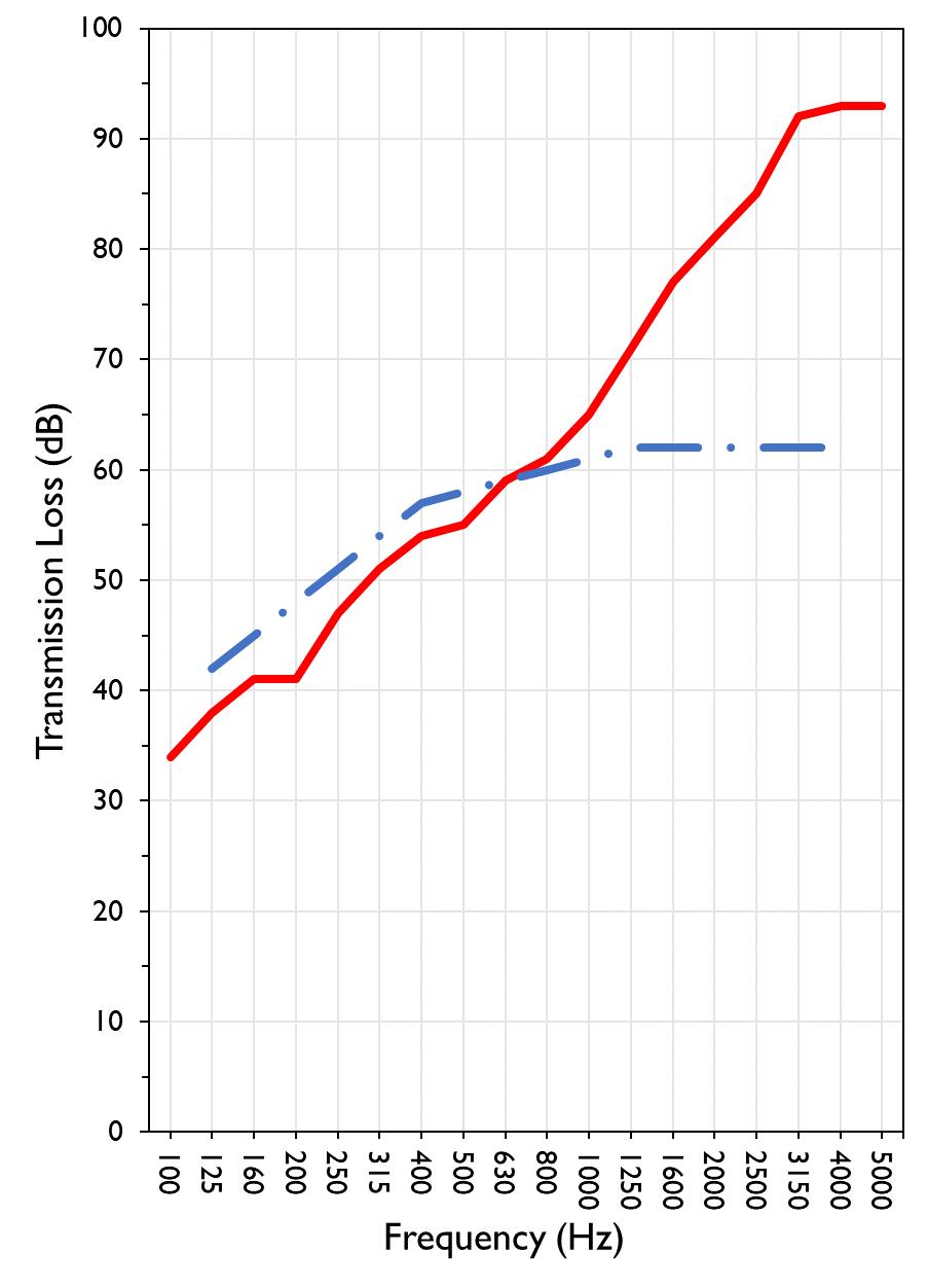
627 RIVERBANK DRIVE GENEVA, IL 60134
630-232-0104
University of Oregon
2024-07-08
Page 15 of 18
Specimen: 1” Maxxon gypcrete 2000 Multifamily, 1-1/8” T&G plywood subfloor screwed 24” OC with #9x3”, cavity filled with: HempWool Acoustibatt 3.5” hemp batt, 2x4 sleepers 24”OC with Rothoblaas Piano B acoustic strips stapled top/bottom, Vaagen Timbers 5-ply CLT 6.875” with plywood spline 3/4”x6” at the joint secured with #9x3” screws at 6” OC (See Full Report)
The following non-accredited data were obtained in accordance with ASTM E90-09 (2016), but extend beyond the defined frequency range of 100Hz to 5,000Hz. These unofficial results are representative of the RAL test environment only and intended for research & comparison purposes. Sampling precision observed during this procedure is reported below. Corrections are detailed in Appendix B.
1/3 Octave Band Sound
627 RIVERBANK DRIVE GENEVA, IL 60134
630-232-0104
University of Oregon
2024-07-08 Page 16 of 18
Specimen: 1” Maxxon gypcrete 2000 Multifamily, 1-1/8” T&G plywood subfloor screwed 24” OC with #9x3”, cavity filled with: HempWool Acoustibatt 3.5” hemp batt, 2x4 sleepers 24”OC with Rothoblaas Piano B acoustic strips stapled top/bottom, Vaagen Timbers 5-ply CLT 6.875” with plywood spline 3/4”x6” at the joint secured with #9x3” screws at 6” OC (See Full Report)
Mark Interpretation
A Measured sound pressure levels in the receive room are within 10 dB of the ambient noise level at the marked frequency band. Receive room levels used to calculate Transmission Loss are corrected according to ASTM E90 Section 10.3.
AA Measured sound pressure levels in the receive room are within 5 dB of the ambient noise level at the marked frequency band. Receive room levels used to calculate Transmission Loss are corrected according to ASTM E90 Section 10.3.1. Transmission Loss values calculated from levels corrected this way will be less than or equal to Transmission Loss values from a hypothetical test using the same specimen and a receive room with idealized ambient sound levels of (-∞) dB.
F The reported Transmission Loss is within 10 dB of the laboratory flanking limit at the marked frequency band. The measured performance of the specimen may be limited by the performance of the laboratory building structure at this frequency band.
Z The reported Transmission Loss at the marked frequency band has been corrected according to ASTM E90 Section A3.2.7 to account for possible sound transmission through the filler assembly.
ZZ The reported Transmission Loss at the marked frequency band has been corrected according to ASTM E90 Section A3.2.8 to account for possible sound transmission through the filler assembly. Transmission Loss values corrected this way will be less than or equal to Transmission Loss values from a hypothetical test using the same specimen and an idealized filler assembly with a Sound Transmission Class rating of (∞).
Specimen: 1” Maxxon gypcrete 2000 Multifamily, 1-1/8” T&G plywood subfloor screwed 24” OC with #9x3”, cavity filled with: HempWool Acoustibatt 3.5” hemp batt, 2x4 sleepers 24”OC with Rothoblaas Piano B acoustic strips stapled top/bottom, Vaagen Timbers 5-ply CLT 6.875” with plywood spline 3/4”x6” at the joint secured with #9x3” screws at 6” OC (See Full Report)
ΔTL, the 95% confidence interval for reported transmission loss values, is calculated from the standard deviation of the sets of measurements for source room sound pressure level, receive room sound pressure level, and receive room sound absorption. This metric is calculated in an effort to quantify the combined influences of room geometry, microphone positioning, and other varying environmental conditions on reported results.
Repeatability, expressed as a 95% confidence interval, is calculated from the standard deviation of transmission loss as obtained from a set of six (6) consecutive tests conducted according to this test method by RAL from 202102-25 through 2021-03-04. The tests were performed on a specimen composed of a 6 in. thick concrete slab, using the same test opening as used in this report. This metric provides an estimate of the variation in results that might be observed if the test were repeated with no change to the installed specimen. Note that repeatability will vary with the construction type.
SABINE 627 RIVERBANK DRIVE GENEVA, IL 60134 630-232-0104
WALLACE
University of Oregon RAL™-TL24-302 2024-07-08 Page 17 of 18
APPENDIX D: Determination of Outdoor Indoor Transmission Class (OITC)
Specimen: 1” Maxxon gypcrete 2000 Multifamily, 1-1/8” T&G plywood subfloor screwed 24” OC with #9x3”, cavity filled with: HempWool Acoustibatt 3.5” hemp batt, 2x4 sleepers 24”OC with Rothoblaas Piano B acoustic strips stapled top/bottom, Vaagen Timbers 5-ply CLT 6.875” with plywood spline 3/4”x6” at the joint secured with #9x3” screws at 6” OC (See Full Report)
The determination of the Outdoor Indoor Transmission Class (OITC) as reported below was made with explicit conformity to the procedures described in the ASTM E1332-22 test standard. Test Method ASTM E90-09 (2016) was used to obtain the sound transmission loss data. This rating is based on an average transportation noise source spectrum and an A-weighted sound level reduction, either of which may be inappropriate for some applications. One-third Octave Band Center Frequency, Hz Reference Sound Spectrum,
Test Specimen
1918 BY WALLACE CLEMENT SABINE 627 RIVERBANK DRIVE GENEVA, IL 60134 630-232-0104
University of Oregon RAL™-TL24-302 2024-07-08 Page 18 of 18
APPENDIX E: Instruments of Traceability
Specimen: 1” Maxxon gypcrete 2000 Multifamily, 1-1/8” T&G plywood subfloor screwed 24” OC with #9x3”, cavity filled with: HempWool Acoustibatt 3.5” hemp batt, 2x4 sleepers 24”OC with Rothoblaas Piano B acoustic strips stapled top/bottom, Vaagen Timbers 5-ply CLT 6.875” with plywood spline 3/4”x6” at the joint secured with #9x3” screws at 6” OC (See Full Report)
System 2 Type 3160-A-042 3160106974 2023-08-11 2024-08-11
Bruel & Kjaer Mic And Preamp C Type 4943-B-001 2311439 2024-03-29 2025-03-29
Bruel & Kjaer Pistonphone Type 4228 2781248 2023-07-12 2024-07-12
EXTECH Hygro 663 SD700 A083663 2023-12-28 2024-12-28
EXTECH Hygro 639 SD700 A.103639 2023-12-01 2024-12-01
APPENDIX F: Revisions to Original Test Report
Specimen: 1” Maxxon gypcrete 2000 Multifamily, 1-1/8” T&G plywood subfloor screwed 24” OC with #9x3”, cavity filled with: HempWool Acoustibatt 3.5” hemp batt, 2x4 sleepers 24”OC with Rothoblaas Piano B acoustic strips stapled top/bottom, Vaagen Timbers 5-ply CLT 6.875” with plywood spline 3/4”x6” at the joint secured with #9x3” screws at 6” OC (See Full Report) Date
2024-07-31 Original report issued
627 RIVERBANK DRIVE GENEVA, IL 60134 630-232-0104
SPONSOR: University of Oregon Sound Transmission Loss Portland, OR RAL™-TL24-303
CONDUCTED: 2024-07-09 Page 1 of 20 ON: Marmoleum Decibel adhered with Sustain 1195, 1” Maxxon gypcrete 2000 Multifamily, 1-1/8” T&G plywood subfloor screwed 24” OC with #9x3”, cavity filled with: HempWool Acoustibatt 3.5” hemp batt, 2x4 sleepers 24”OC with Rothoblaas Piano B acoustic strips stapled top/bottom, Vaagen Timbers 5-ply CLT 6.875” with plywood spline 3/4”x6” at the joint secured with #9x3” screws at 6” OC
Riverbank Acoustical Laboratories™ is accredited by the U.S. Department of Commerce, National Institute of Standards and Technology (NIST) under the National Voluntary Laboratory Accreditation Program (NVLAP) as an ISO 17025:2017 Laboratory (NVLAP Lab Code: 100227-0) and for this test procedure. The test reported in this document conformed explicitly with ASTM E90-09 (2016): "Standard Test Method for Laboratory Measurement of Airborne Sound Transmission Loss of Building Partitions and Elements." The single number rating of the specimen was calculated according to ASTM E413-22: "Classification for Rating Sound Insulation." A description of the measurement procedure and room specifications is available upon request. The transmission loss values are for a single direction of measurement. The results presented in this report apply to the sample as received from the test sponsor.
The test specimen was designated by the sponsor as Marmoleum Decibel adhered with Sustain 1195, 1” Maxxon gypcrete 2000 Multifamily, 1-1/8” T&G plywood subfloor screwed 24” OC with #9x3”, cavity filled with: HempWool Acoustibatt 3.5” hemp batt, 2x4 sleepers 24”OC with Rothoblaas Piano B acoustic strips stapled top/bottom, Vaagen Timbers 5-ply CLT 6.875” with plywood spline 3/4”x6” at the joint secured with #9x3” screws at 6” OC. The following nominal product information was provided by the sponsor prior to testing. The accuracy of such sponsor-provided information can affect the validity of the test results.
Provided Description: Marmoleum Decibel adhered with Sustain 1195, 1” Maxxon gypcrete 2000 Multifamily, 1-1/8” T&G plywood subfloor screwed 24” OC with #9x3", cavity filled with: HempWool Acoustibatt 3.5” hemp batt, 2x4 sleepers 24”OC with Rothoblaas Piano B acoustic strips stapled top/bottom, Vaagen Timbers 5-ply CLT 6.875” with plywood spline 3/4”x6” at the joint secured with #9x3” screws at 6” OC
Manufacturer: University of Oregon
627 RIVERBANK DRIVE GENEVA, IL 60134 630-232-0104
University of Oregon
2024-07-09
Page 2 of 20
The building contractor (Seth Priser) and RAL staff compiled a detailed construction specification as follows:
Cross-Laminated Timber (CLT)
Materials: 5-Ply Cross-Laminated Timber
Dimensions: 2 panels @ 1219 mm (48 in.) by 4229 mm (166.5 in.)
Thickness: 171 mm (6.75 in.)
Overall Weight: 953.45 kg (2102 lbs)
Mass Per Unit Volume: 539 kg/m3 (33.7 lbs/ft3)
Installation: CLT panels laid on 152 mm (6 in.) wide knee walls in test opening and butted to one another without sealant/adhesive.
3/4”x3” Rabbet on top side of one edge of each panel where they butt allowing a loose spline (below) to insert and join the two
¾” CDX Loose Spline
Materials: 3/4” x 6” plywood spline
Dimensions: 1 piece @ 151 mm (5.9375 in.) wide by 2438 mm (96 in.) 1 piece @ 151 mm (5.9375 in.) wide by 1791 mm (70.5 in.)
Thickness: 19 mm (0.75 in.)
Overall Weight: 6.46 kg (14.25 lbs)
Mass Per Unit Length: 1.53 kg/m (1.03 lbs/ft)
Installation: Set in Rabbets of both CLT’s and screwed in place.
Fasteners: WSV Bugle head sub-floor screws, length @ 76 mm (3 in.)
Fastener Spacing: 6” o.c. on a line 3” from each edge of the spline (Centered on the rabbet of the CLT)
Piano B 40/40 (Lower Layer)
Manufacturer: Rothoblaas
Dimensions: 2 strips @ 40 mm (1.5625 in.) wide by 4267 mm (168 in.) long 8 strips @ 2362 mm (93 in.) wide by 40 mm (1.5625 in.) long
Thickness: 6.76 mm (0.266 in.)
Overall Weight: 4.59 kg (10.125 lbs)
Mass Per Unit Volume: 624 kg/m3 (40.0 lbs/ft3)
Installation: Fastened to underside of 2” x 4” wood sleepers with staples
Fasteners: Arrow staples, length @ 13 mm (0.5 in.)
University of Oregon
2024-07-09
SPECIMEN MEASUREMENTS & TEST CONDITIONS (continued)
2” by 4” SPF Framing Sleepers
Materials: Nominal 2”x 4” framing lumber
Page 3 of 20
Dimensions: 2 pieces @ 38 mm (1.5 in.) wide by 4255 mm (167.5 in.) long
8 pieces @ 2369 mm (93.25 in.) wide by 38 mm (1.5 in.) long
Depth: 89 mm (3.5 in.)
Overall Weight: 49.33 kg (108.75 lbs)
Mass Per Unit Length: 1.80 kg/m (1.21 lbs/ft)
Installation: Sleepers laid over CLT, resting on lower layer Piano B 40/40
Longer sleepers parallel to CLT like a rim joist
Shorter sleepers set like floor joists between rim joists
Shorter sleepers spaced approx. 610 mm (24 in.) on center
Shorter sleepers fastened to longer sleepers with screws, 2 screws per connection point
Fasteners: WSV Bugle head sub-floor screws, length @ 76 mm (3 in.)
Piano B 40/40 (Upper Layer)
Manufacturer: Rothoblaas
Dimensions: 2 strips @ 40 mm (1.5625 in.) wide by 4267 mm (168 in.) long 8 strips @ 2362 mm (93 in.) wide by 40 mm (1.5625 in.) long
Thickness: 6.76 mm (0.266 in.)
Overall Weight: 4.59 kg (10.125 lbs)
Mass Per Unit Volume: 624 kg/m3 (40.0 lbs/ft3)
Installation: Fastened to top of 2” x 4” wood sleepers with staples
Fasteners: Arrow staples, length @ 13 mm (0.5 in.)
Materials: 3” Hemp fiber board
Manufacturer: Hempitecture
Dimensions: 7 pieces @ 572 mm (22.5 in.) wide by 2369 mm (93.25 in.) long
Depth: 76 mm (3 in.)
Overall Weight: 37.53 kg (82.75 lbs)
Mass Per Unit Volume: 52.0 kg/m3 (3.25 lbs/ft3)
Installation: Friction fit between sleepers and on top of CLT
University of Oregon
2024-07-09
SPECIMEN MEASUREMENTS & TEST CONDITIONS (continued)
Plywood Subfloor
Materials: T&G Plywood
Dimensions: 1 piece @ 1219 mm (48 in.) wide by 1829 mm (72 in.)
1 piece @ 1219 mm (48 in.) wide by 2438 mm (96 in.)
1 piece @ 1219 mm (48 in.) wide by 1822 mm (71.75 in.)
1 piece @ 1219 mm (48 in.) wide by 2432 mm (95.75 in.)
Thickness: 29 mm (1.125 in.)
Overall Weight: 173.5 kg (382.5 lbs)
Mass Per Unit Volume: 584 kg/m3 (36.5 lbs/ft3)
Installation: Placed over upper layer Piano B 40/40 over sleepers
Fastened to sleepers through Piano B 40/40 with screws
Plywood piece joints staggered
Fasteners: WSV Bugle head sub-floor screws, length @ 76 mm (3 in.)
Fastener Spacing: 610 mm (24 in.) on center
Gypcrete
Page 4 of 20
Materials: Gypcrete mix
Manufacturer: Maxxon
Dimensions: 2438 mm (96 in.) by 4267 mm (168 in.) as installed
Thickness: Approx 25 mm (1 in.)
Mix Ratio: 2.5 gallons water / 40 lbs gypcrete / 75 lbs all-purpose sand
Overall Dry Weight: 469.47 kg (1035 lbs)
Mass Per Unit Volume: 1780 kg/m3 (111 lbs/ft3)
Installation: Poured over plywood subfloor
Gauge rake was used to level product to 1” of thickness
Wet gypcrete mix was poured on (2024-07-01, approx. 3:40 PM)
University of Oregon
2024-07-09
SPECIMEN MEASUREMENTS & TEST CONDITIONS (continued)
Adhesive
Materials: Sustain 1195 Sheet and Tile adhesive
Manufacturer: Forbo
Dimensions: Approx. 2438 mm (96 in.) by 4267 mm (168 in.) as installed
Overall Weight: 2.95 kg (6.5 lbs)
Mass Per Unit Area: 0.28 kg/m2 (0.06 lbs/ft2)
Flooring
Page 5 of 20
Installation: Troweled directly to gypcrete with a 1/16x1/16x1/16 square notch trowel Once troweled, adhesive was left “open” for 15 min to allow it to “tack” before flooring was installed.
Materials: Marmoleum Decibel
Manufacturer: Forbo
Dimensions: 2 pieces @ 2007 mm (79 in.) by 2464 mm (97 in.) 1 piece @ 260 mm (10.25 in.) by 2464 mm (97 in.)
Thickness: 6 mm (0.25 in.)
Overall Weight: 35.38 kg (78 lbs)
Mass Per Unit Volume: 529 kg/m3 (33.0 lbs/ft3)
Installation: Two (2) 79” segments perpendicular to Plywood 10” strip to complete Joints staggered from parallel plywood joints by + 6” Rolled with 100lb roller in each direction
University of Oregon
2024-07-09 Page 6 of 20
SPECIMEN MEASUREMENTS & TEST CONDITIONS (continued)
Overall Specimen Measurements
Dimensions: 2.44 m (96.0 in) wide by 3.86 m (152.0 in) high
Thickness: 0.33 m (13.125 in)
Weight: 1734.31 kg (3823.5 lbs)
Overall Area: 9.414 m² (101.33 ft²)
Mass per Unit Area: 166.68 kg/m² (34.14 lbs/ft²)
Test Aperture
Opening Size: 4.27 m (14.0 ft) x 6.10 m (20.0 ft)
Filler Wall: Yes
Aperture Size: 2.44 m (96.0 in) wide by 3.86 m (152.0 in) high
Transmission Area: 9.414 m² (101.33 ft²)
Sealed: Entire periphery (both sides) with dense mastic
Test Environment
Source Room
Volume: 130.9 m³
Temperature: 22.2 °C ± 0.0 °C
Relative Humidity: 62.0 % ± 2.0 %
Receive Room
Volume: 81.44 m³
Temperature: 21.7 °C ± 0.0 °C
Relative Humidity: 63.0 % ± 0.0 %
Requirements
Temperature: 22º C +/- 2° C, not more than 3° C change over all tests.
Relative Humidity: ≥ 30%, not more than +/- 3% change over all tests.
University of Oregon
2024-07-09 Page 7 of 20
University of Oregon
2024-07-09
Page 8 of 20
University of Oregon
2024-07-09 Page 9 of 20
University of Oregon
2024-07-09 Page 10 of 20
University of Oregon
2024-07-09 Page 11 of 20
University of Oregon
2024-07-09 Page 12 of 20
University of Oregon
2024-07-09 Page 13 of 20
University of Oregon
2024-07-09 Page 14 of 20
University of Oregon
2024-07-09 Page 15 of 20
Sound transmission loss values are tabulated at the eighteen standard frequency bands. A graphic presentation of the data and additional information appear on the following pages. The precision of the transmission loss test data is within the limits set by the ASTM Standard E90-09 (2016). See Appendix A for identification of corrections applied to the reported data.
ABBREVIATION INDEX
FREQ. = 1/3 OCTAVE BAND CENTER FREQUENCY, Hz
TL = TRANSMISSION LOSS, dB
ΔTL = 95% CONFIDENCE INTERVAL FOR TL MEASUREMENTS, dB
DEF. = DEFICIENCIES, dB BELOW SHIFTED STC CONTOUR (SUM OF DEF = 25)
STC = SOUND TRANSMISSION CLASS
Tested by_____________________________ Report by__________________________
Marc Sciaky
Keith Kimberling Senior Experimentalist Test Engineer
Approved by _______________________
Eric P. Wolfram Laboratory Manager
627 RIVERBANK DRIVE
GENEVA, IL 60134
630-232-0104
University of Oregon
2024-07-09 Page 16 of 20
Marmoleum Decibel adhered with Sustain 1195, 1” Maxxon gypcrete 2000 Multifamily, 1-1/8” T&G plywood subfloor screwed 24” OC with #9x3”, cavity filled with: HempWool Acoustibatt 3.5” hemp batt, 2x4 sleepers 24”OC with Rothoblaas Piano B acoustic strips stapled top/bottom, Vaagen Timbers
5-ply CLT 6.875” with plywood spline 3/4”x6” at the joint secured with #9x3” screws at 6” OC
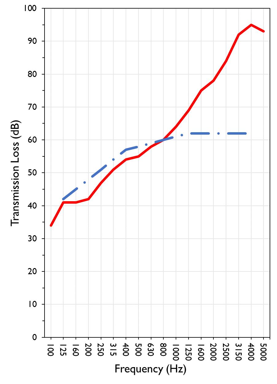
TRANSMISSION LOSS
SOUND TRANSMISSION CLASS CONTOUR
627 RIVERBANK DRIVE GENEVA, IL 60134
630-232-0104
University of Oregon
1918 BY WALLACE CLEMENT SABINE
2024-07-09 Page 17 of 20
Specimen: Marmoleum Decibel adhered with Sustain 1195, 1” Maxxon gypcrete 2000 Multifamily, 1-1/8” T&G plywood subfloor screwed 24” OC with #9x3”, cavity filled with: HempWool Acoustibatt 3.5” hemp batt, 2x4 sleepers 24”OC with Rothoblaas Piano B acoustic strips stapled top/bottom, Vaagen Timbers 5-ply CLT 6.875” with plywood spline 3/4”x6” at the joint secured with #9x3” screws at 6” OC (See Full Report)
The following non-accredited data were obtained in accordance with ASTM E90-09 (2016), but extend beyond the defined frequency range of 100Hz to 5,000Hz. These unofficial results are representative of the RAL test environment only and intended for research & comparison purposes. Sampling precision observed during this procedure is reported below. Corrections are detailed in Appendix B.
1/3 Octave Band Sound
627 RIVERBANK DRIVE GENEVA, IL 60134
630-232-0104
University of Oregon
2024-07-09 Page 18 of 20
Specimen: Marmoleum Decibel adhered with Sustain 1195, 1” Maxxon gypcrete 2000 Multifamily, 1-1/8” T&G plywood subfloor screwed 24” OC with #9x3”, cavity filled with: HempWool Acoustibatt 3.5” hemp batt, 2x4 sleepers 24”OC with Rothoblaas Piano B acoustic strips stapled top/bottom, Vaagen Timbers 5-ply CLT 6.875” with plywood spline 3/4”x6” at the joint secured with #9x3” screws at 6” OC (See Full Report)
Mark Interpretation
A Measured sound pressure levels in the receive room are within 10 dB of the ambient noise level at the marked frequency band. Receive room levels used to calculate Transmission Loss are corrected according to ASTM E90 Section 10.3.
AA Measured sound pressure levels in the receive room are within 5 dB of the ambient noise level at the marked frequency band. Receive room levels used to calculate Transmission Loss are corrected according to ASTM E90 Section 10.3.1. Transmission Loss values calculated from levels corrected this way will be less than or equal to Transmission Loss values from a hypothetical test using the same specimen and a receive room with idealized ambient sound levels of (-∞) dB.
F The reported Transmission Loss is within 10 dB of the laboratory flanking limit at the marked frequency band. The measured performance of the specimen may be limited by the performance of the laboratory building structure at this frequency band.
Z The reported Transmission Loss at the marked frequency band has been corrected according to ASTM E90 Section A3.2.7 to account for possible sound transmission through the filler assembly.
ZZ The reported Transmission Loss at the marked frequency band has been corrected according to ASTM E90 Section A3.2.8 to account for possible sound transmission through the filler assembly. Transmission Loss values corrected this way will be less than or equal to Transmission Loss values from a hypothetical test using the same specimen and an idealized filler assembly with a Sound Transmission Class rating of (∞).
Specimen: Marmoleum Decibel adhered with Sustain 1195, 1” Maxxon gypcrete 2000 Multifamily, 1-1/8” T&G plywood subfloor screwed 24” OC with #9x3”, cavity filled with: HempWool Acoustibatt 3.5” hemp batt, 2x4 sleepers 24”OC with Rothoblaas Piano B acoustic strips stapled top/bottom, Vaagen Timbers 5-ply CLT 6.875” with plywood spline 3/4”x6” at the joint secured with #9x3” screws at 6” OC (See Full Report)
ΔTL, the 95% confidence interval for reported transmission loss values, is calculated from the standard deviation of the sets of measurements for source room sound pressure level, receive room sound pressure level, and receive room sound absorption. This metric is calculated in an effort to quantify the combined influences of room geometry, microphone positioning, and other varying environmental conditions on reported results.
Repeatability, expressed as a 95% confidence interval, is calculated from the standard deviation of transmission loss as obtained from a set of six (6) consecutive tests conducted according to this test method by RAL from 202102-25 through 2021-03-04. The tests were performed on a specimen composed of a 6 in. thick concrete slab, using the same test opening as used in this report. This metric provides an estimate of the variation in results that might be observed if the test were repeated with no change to the installed specimen. Note that repeatability will vary with the construction type.
627 RIVERBANK DRIVE GENEVA, IL 60134
630-232-0104
University of Oregon RAL™-TL24-303 2024-07-09 Page 19 of 20
APPENDIX D: Determination of Outdoor Indoor Transmission Class (OITC)
Specimen: Marmoleum Decibel adhered with Sustain 1195, 1” Maxxon gypcrete 2000 Multifamily, 11/8” T&G plywood subfloor screwed 24” OC with #9x3”, cavity filled with: HempWool Acoustibatt 3.5” hemp batt, 2x4 sleepers 24”OC with Rothoblaas Piano B acoustic strips stapled top/bottom, Vaagen Timbers 5-ply CLT 6.875” with plywood spline 3/4”x6” at the joint secured with #9x3” screws at 6” OC (See Full Report)
The determination of the Outdoor Indoor Transmission Class (OITC) as reported below was made with explicit conformity to the procedures described in the ASTM E1332-22 test standard. Test Method ASTM E90-09 (2016) was used to obtain the sound transmission loss data. This rating is based on an average transportation noise source spectrum and an A-weighted sound level reduction, either of which may be inappropriate for some applications.
One-third Octave Band Center Frequency, Hz Reference Sound Spectrum,
627 RIVERBANK DRIVE GENEVA, IL 60134 630-232-0104
University of Oregon RAL™-TL24-303 2024-07-09 Page 20 of 20
APPENDIX E: Instruments of Traceability
Specimen: Marmoleum Decibel adhered with Sustain 1195, 1” Maxxon gypcrete 2000 Multifamily, 1-1/8” T&G plywood subfloor screwed 24” OC with #9x3”, cavity filled with: HempWool Acoustibatt 3.5” hemp batt, 2x4 sleepers 24”OC with Rothoblaas Piano B acoustic strips stapled top/bottom, Vaagen Timbers 5-ply CLT 6.875” with plywood spline 3/4”x6” at the joint secured with #9x3” screws at 6” OC (See Full Report)
System 2 Type 3160-A-042 3160106974 2023-08-11 2024-08-11
Bruel & Kjaer Mic And Preamp C Type 4943-B-001 2311439 2024-03-29 2025-03-29
Bruel & Kjaer Pistonphone Type 4228 2781248 2023-07-12 2024-07-12
EXTECH Hygro 663 SD700 A083663 2023-12-28 2024-12-28
EXTECH Hygro 639 SD700 A.103639 2023-12-01 2024-12-01
APPENDIX F: Revisions to Original Test Report
Specimen: Marmoleum Decibel adhered with Sustain 1195, 1” Maxxon gypcrete 2000 Multifamily, 11/8” T&G plywood subfloor screwed 24” OC with #9x3”, cavity filled with: HempWool
Acoustibatt 3.5” hemp batt, 2x4 sleepers 24”OC with Rothoblaas Piano B acoustic strips stapled top/bottom, Vaagen Timbers 5-ply CLT 6.875” with plywood spline 3/4”x6” at the joint secured with #9x3” screws at 6” OC (See Full Report)
Date Revision
2024-07-31 Original report issued
627 RIVERBANK DRIVE
GENEVA, IL 60134
630-232-0104
SPONSOR: University of Oregon Sound Transmission Loss Portland, OR RAL™-TL24-326
CONDUCTED: 2024-07-22
Page 1 of 16 ON: 1” Maxxon gypcrete 2000 Multifamily, Certainteed MemBrain vapor retarder, 3” of 3/8” limestone chip, Hempitecture 2” hemp fiber board, Vaagen Timbers 5-ply CLT 6.875” with plywood spline 3/4”x6” at the joint secured with #9x3” screws at 6” OC
Riverbank Acoustical Laboratories™ is accredited by the U.S. Department of Commerce, National Institute of Standards and Technology (NIST) under the National Voluntary Laboratory Accreditation Program (NVLAP) as an ISO 17025:2017 Laboratory (NVLAP Lab Code: 100227-0) and for this test procedure. The test reported in this document conformed explicitly with ASTM E90-09 (2016): "Standard Test Method for Laboratory Measurement of Airborne Sound Transmission Loss of Building Partitions and Elements." The single number rating of the specimen was calculated according to ASTM E413-22: "Classification for Rating Sound Insulation." A description of the measurement procedure and room specifications is available upon request. The transmission loss values are for a single direction of measurement. The results presented in this report apply to the sample as received from the test sponsor.
The test specimen was designated by the sponsor as 1” Maxxon gypcrete 2000 Multifamily, Certainteed MemBrain vapor retarder, 3” of 3/8” limestone chip, Hempitecture 2” hemp fiber board, Vaagen Timbers 5-ply CLT 6.875” with plywood spline 3/4”x6” at the joint secured with #9x3” screws at 6” OC. The following nominal product information was provided by the sponsor prior to testing. The accuracy of such sponsor-provided information can affect the validity of the test results.
Provided Description: 1” Maxxon gypcrete 2000 Multifamily, Certainteed MemBrain vapor retarder, 3” of 3/8" limestone chip, Hempitecture 2” hemp fiber board, Vaagen Timbers 5-ply CLT 6.875” with plywood spline 3/4”x6” at the joint secured with #9x3” screws at 6” OC Manufacturer: University of Oregon
627 RIVERBANK DRIVE GENEVA, IL 60134 630-232-0104
University of Oregon
2024-07-22
Page 2 of 16
The building contractor (Seth Priser) and RAL staff compiled a detailed construction specification as follows:
Cross-Laminated Timber (CLT)
Materials: 5-Ply Cross-Laminated Timber
Dimensions: 2 panels @ 1219 mm (48 in.) by 4229 mm (166.5 in.)
Thickness: 171 mm (6.75 in.)
Overall Weight: 953.45 kg (2102 lbs)
Mass Per Unit Volume: 539 kg/m3 (33.7 lbs/ft3)
Installation: CLT panels laid on 152 mm (6 in.) wide knee walls in test opening and butted to one another without sealant/adhesive.
3/4”x3” Rabbet on top side of one edge of each panel where they butt allowing a loose spline (below) to insert and join the two
Materials: 3/4” x 6” plywood spline
Dimensions: 1 piece @ 151 mm (5.9375 in.) wide by 2438 mm (96 in.) 1 piece @ 151 mm (5.9375 in.) wide by 1791 mm (70.5 in.)
Thickness: 19 mm (0.75 in.)
Overall Weight: 6.46 kg (14.25 lbs)
Mass Per Unit Length: 1.53 kg/m (1.03 lbs/ft)
Installation: Set in Rabbets of both CLT’s and screwed in place.
Fasteners: WSV Bugle head sub-floor screws, length @ 76 mm (3 in.)
Fastener Spacing: 6” o.c. on a line 3” from each edge of the spline (Centered on the rabbet of the CLT)
Hemp Board
Materials: 2” Hemp fiber board
Manufacturer: Hempitecture
Dimensions: 3 pieces @ 1216 mm (47.875 in.) wide by 2448 mm (96.375 in.) long 1 piece @ 613 mm (24.125 in.) wide by 2448 mm (96.375 in.) long
Depth: 51 mm (2 in.)
Overall Weight: 69.51 kg (153.25 lbs)
Mass Per Unit Volume: 131 kg/m3 (8.19 lbs/ft3)
Installation: Loose laid directly on top of CLT Perpendicular to CLT
627 RIVERBANK DRIVE GENEVA, IL 60134 630-232-0104
University of Oregon
2024-07-22
SPECIMEN MEASUREMENTS & TEST CONDITIONS (continued)
Crushed Limestone
Materials: CA-16 3/8” chip crushed limestone
Page 3 of 16
Dimensions: 2438 mm (96 in.) wide by 4267 mm (168 in.) long, as installed
Depth: 76 mm (3 in.)
Overall Weight: 1224.02 kg (2698.5 lbs)
Installation: Loose laid on top of the Hemp fiberboard ½” polystyrene used as an isolation around the perimeter
Vapor Barrier
Materials: Membrain Vapor barrier
Manufacturer: Saint Gobain
Dimensions: Approx. 2438 mm (96 in.) by 4267 mm (168 in.) as installed
Overall Weight: 0.79 kg (1.75 lbs)
Mass Per Unit Area: 0.08 kg/m2 (0.02 lbs/ft2)
Installation: Loose laid over crushed limestone
Gypcrete
Materials: Gypcrete mix
Manufacturer: Maxxon
Dimensions: 2438 mm (96 in.) by 4267 mm (168 in.) as installed
Thickness: 25 mm (1 in.)
Mix Ratio: 2.5 gallons water / 40 lbs gypcrete / 75 lbs all-purpose sand
Overall Dry Weight: 521.63 kg (1150 lbs)
Mass Per Unit Volume: 1970 kg/m3 (123 lbs/ft3)
Installation: Poured over vapor barrier
A screed was used to spread the wet gypcrete mix
Wet gypcrete mix was poured on (2024-07-10, approx. 4:30 PM)
University of Oregon
2024-07-22 Page 4 of 16
SPECIMEN MEASUREMENTS & TEST CONDITIONS (continued)
Overall Specimen Measurements
Dimensions: 2.44 m (96.0 in) wide by 3.86 m (152.0 in) high
Thickness: 0.32 m (12.75 in)
Weight: 2775.87 kg (6119.75 lbs)
Overall Area: 9.414 m² (101.33 ft²)
Mass per Unit Area: 266.78 kg/m² (54.64 lbs/ft²)
Test Aperture
Opening Size: 4.27 m (14.0 ft) x 6.10 m (20.0 ft)
Filler Wall: Yes
Aperture Size: 2.44 m (96.0 in) wide by 3.86 m (152.0 in) high
Transmission Area: 9.414 m² (101.33 ft²)
Sealed: Entire periphery (both sides) with dense mastic
Test Environment
Source Room
Volume: 130.9 m³
Temperature: 23.3 °C ± 0.0 °C
Relative Humidity: 68.0 % ± 0.0 %
Receive Room
Volume: 81.44 m³
Temperature: 22.2 °C ± 0.0 °C
Relative Humidity: 68.0 % ± 2.0 %
Requirements
Temperature: 22º C +/- 2° C, not more than 3° C change over all tests.
Relative Humidity: ≥ 30%, not more than +/- 3% change over all tests.
University of Oregon
2024-07-22
Page 5 of 16
University of Oregon
2024-07-22
Page 6 of 16
University of Oregon
2024-07-22 Page 7 of 16
University of Oregon
2024-07-22 Page 8 of 16
University of Oregon
2024-07-22 Page 9 of 16
University of Oregon
2024-07-22 Page 10 of 16
University of Oregon RAL™-TL24-326 2024-07-22 Page 11 of 16
Sound transmission loss values are tabulated at the eighteen standard frequency bands. A graphic presentation of the data and additional information appear on the following pages. The precision of the transmission loss test data is within the limits set by the ASTM Standard E90-09 (2016). See Appendix A for identification of corrections applied to the reported data.
ABBREVIATION INDEX
FREQ. = 1/3 OCTAVE BAND CENTER FREQUENCY, Hz
TL = TRANSMISSION LOSS, dB
ΔTL = 95% CONFIDENCE INTERVAL FOR TL MEASUREMENTS, dB
DEF. = DEFICIENCIES, dB BELOW SHIFTED STC CONTOUR (SUM OF DEF = 29)
STC = SOUND TRANSMISSION CLASS Tested by_____________________________
Approved by
Eric P. Wolfram Laboratory Manager
627 RIVERBANK DRIVE GENEVA, IL 60134 630-232-0104
University of Oregon
2024-07-22 Page 12 of 16
1” Maxxon gypcrete 2000 Multifamily, Certainteed MemBrain vapor retarder, 3” of 3/8” limestone chip, Hempitecture 2” hemp fiber board, Vaagen Timbers 5-ply CLT 6.875” with plywood spline 3/4”x6” at the joint secured with #9x3” screws at 6” OC
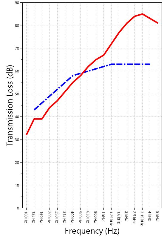
627 RIVERBANK DRIVE GENEVA, IL 60134 630-232-0104
University of Oregon RAL™-TL24-326 2024-07-22
Page 13 of 16
Specimen: 1” Maxxon gypcrete 2000 Multifamily, Certainteed MemBrain vapor retarder, 3” of 3/8” limestone chip, Hempitecture 2” hemp fiber board, Vaagen Timbers 5-ply CLT 6.875” with plywood spline 3/4”x6” at the joint secured with #9x3” screws at 6” OC (See Full Report)
The following non-accredited data were obtained in accordance with ASTM E90-09 (2016), but extend beyond the defined frequency range of 100Hz to 5,000Hz. These unofficial results are representative of the RAL test environment only and intended for research & comparison purposes. Sampling precision observed during this procedure is reported below. Corrections are detailed in Appendix B.
627 RIVERBANK DRIVE GENEVA, IL 60134
630-232-0104
University of Oregon RAL™-TL24-326 2024-07-22 Page 14 of 16
Specimen: 1” Maxxon gypcrete 2000 Multifamily, Certainteed MemBrain vapor retarder, 3” of 3/8” limestone chip, Hempitecture 2” hemp fiber board, Vaagen Timbers 5-ply CLT 6.875” with plywood spline 3/4”x6” at the joint secured with #9x3” screws at 6” OC (See Full Report)
Mark Interpretation
A Measured sound pressure levels in the receive room are within 10 dB of the ambient noise level at the marked frequency band. Receive room levels used to calculate Transmission Loss are corrected according to ASTM E90 Section 10.3.
AA Measured sound pressure levels in the receive room are within 5 dB of the ambient noise level at the marked frequency band. Receive room levels used to calculate Transmission Loss are corrected according to ASTM E90 Section 10.3.1. Transmission Loss values calculated from levels corrected this way will be less than or equal to Transmission Loss values from a hypothetical test using the same specimen and a receive room with idealized ambient sound levels of (-∞) dB.
F The reported Transmission Loss is within 10 dB of the laboratory flanking limit at the marked frequency band. The measured performance of the specimen may be limited by the performance of the laboratory building structure at this frequency band.
Z The reported Transmission Loss at the marked frequency band has been corrected according to ASTM E90 Section A3.2.7 to account for possible sound transmission through the filler assembly.
ZZ The reported Transmission Loss at the marked frequency band has been corrected according to ASTM E90 Section A3.2.8 to account for possible sound transmission through the filler assembly. Transmission Loss values corrected this way will be less than or equal to Transmission Loss values from a hypothetical test using the same specimen and an idealized filler assembly with a Sound Transmission Class rating of (∞).
Specimen: 1” Maxxon gypcrete 2000 Multifamily, Certainteed MemBrain vapor retarder, 3” of 3/8” limestone chip, Hempitecture 2” hemp fiber board, Vaagen Timbers 5-ply CLT 6.875” with plywood spline 3/4”x6” at the joint secured with #9x3” screws at 6” OC (See Full Report)
ΔTL, the 95% confidence interval for reported transmission loss values, is calculated from the standard deviation of the sets of measurements for source room sound pressure level, receive room sound pressure level, and receive room sound absorption. This metric is calculated in an effort to quantify the combined influences of room geometry, microphone positioning, and other varying environmental conditions on reported results.
Repeatability, expressed as a 95% confidence interval, is calculated from the standard deviation of transmission loss as obtained from a set of six (6) consecutive tests conducted according to this test method by RAL from 202102-25 through 2021-03-04. The tests were performed on a specimen composed of a 6 in. thick concrete slab, using the same test opening as used in this report. This metric provides an estimate of the variation in results that might be observed if the test were repeated with no change to the installed specimen. Note that repeatability will vary with the construction type.
University of Oregon RAL™-TL24-326 2024-07-22 Page 15 of 16
APPENDIX D: Determination of Outdoor Indoor Transmission Class (OITC)
Specimen: 1” Maxxon gypcrete 2000 Multifamily, Certainteed MemBrain vapor retarder, 3” of 3/8” limestone chip, Hempitecture 2” hemp fiber board, Vaagen Timbers 5-ply CLT 6.875” with plywood spline 3/4”x6” at the joint secured with #9x3” screws at 6” OC (See Full Report)
The determination of the Outdoor Indoor Transmission Class (OITC) as reported below was made with explicit conformity to the procedures described in the ASTM E1332-22 test standard. Test Method ASTM E90-09 (2016) was used to obtain the sound transmission loss data. This rating is based on an average transportation noise source spectrum and an A-weighted sound level reduction, either of which may be inappropriate for some applications.
One-third Octave Band Center Frequency, Hz Reference Sound Spectrum, dB Test Specimen Transmission
627 RIVERBANK DRIVE GENEVA, IL 60134 630-232-0104
University of Oregon RAL™-TL24-326 2024-07-22 Page 16 of 16
APPENDIX E: Instruments of Traceability
Specimen: 1” Maxxon gypcrete 2000 Multifamily, Certainteed MemBrain vapor retarder, 3” of 3/8” limestone chip, Hempitecture 2” hemp fiber board, Vaagen Timbers 5-ply CLT 6.875” with plywood spline 3/4”x6” at the joint secured with #9x3” screws at 6” OC (See Full Report)
Description
System 2 Type 3160-A-042 3160106974 2023-08-11 2024-08-11
Bruel & Kjaer Mic And Preamp C Type 4943-B-001 2311439 2024-03-29 2025-03-29
Bruel & Kjaer Sound Level Calibrator Type 4230 861609 2023-12-20 2024-12-20
EXTECH Hygro 663 SD700 A083663 2023-12-28 2024-12-28
EXTECH Hygro 639 SD700 A.103639 2023-12-01 2024-12-01
APPENDIX F: Revisions to Original Test Report
Specimen: 1” Maxxon gypcrete 2000 Multifamily, Certainteed MemBrain vapor retarder, 3” of 3/8” limestone chip, Hempitecture 2” hemp fiber board, Vaagen Timbers 5-ply CLT 6.875” with plywood spline 3/4”x6” at the joint secured with #9x3” screws at 6” OC (See Full Report)
Date Revision
2024-07-31 Original report issued
2024-09-17 Page 16: Calibrator added to instruments of traceability -EPW
627 RIVERBANK DRIVE GENEVA, IL 60134 630-232-0104
WALLACE CLEMENT SABINE
SPONSOR: University of Oregon Sound Transmission Loss Portland, OR RAL™-TL24-338
CONDUCTED: 2024-07-25 Page 1 of 18 ON: Marmoleum Decibel adhered with Sustain 1195, 1” Maxxon gypcrete 2000 Multifamily, Certainteed MemBrain vapor retarder, 3” of 3/8” limestone chip, Hempitecture 2” hemp fiber board, Vaagen Timbers 5-ply CLT 6.875” with plywood spline 3/4”x6” at the joint secured with #9x3” screws at 6” OC
Riverbank Acoustical Laboratories™ is accredited by the U.S. Department of Commerce, National Institute of Standards and Technology (NIST) under the National Voluntary Laboratory Accreditation Program (NVLAP) as an ISO 17025:2017 Laboratory (NVLAP Lab Code: 100227-0) and for this test procedure. The test reported in this document conformed explicitly with ASTM E90-09 (2016): "Standard Test Method for Laboratory Measurement of Airborne Sound Transmission Loss of Building Partitions and Elements." The single number rating of the specimen was calculated according to ASTM E413-22: "Classification for Rating Sound Insulation." A description of the measurement procedure and room specifications is available upon request. The transmission loss values are for a single direction of measurement. The results presented in this report apply to the sample as received from the test sponsor.
The test specimen was designated by the sponsor as Marmoleum Decibel adhered with Sustain 1195, 1” Maxxon gypcrete 2000 Multifamily, Certainteed MemBrain vapor retarder, 3” of 3/8” limestone chip, Hempitecture 2” hemp fiber board, Vaagen Timbers 5-ply CLT 6.875” with plywood spline 3/4”x6” at the joint secured with #9x3” screws at 6” OC. The following nominal product information was provided by the sponsor prior to testing. The accuracy of such sponsor-provided information can affect the validity of the test results.
Provided Description: Marmoleum Decibel adhered with Sustain 1195, 1” Maxxon gypcrete 2000 Multifamily, Certainteed MemBrain vapor retarder, 3” of 3/8" limestone chip, Hempitecture 2” hemp fiber board, Vaagen Timbers 5ply CLT 6.875” with plywood spline 3/4”x6” at the joint secured with #9x3” screws at 6” OC
Manufacturer: University of Oregon
627 RIVERBANK DRIVE GENEVA, IL 60134 630-232-0104
University of Oregon RAL™-TL24-338 2024-07-25
Page 2 of 18
The building contractor (Seth Priser) and RAL staff compiled a detailed construction specification as follows:
Cross-Laminated Timber (CLT)
Materials: 5-Ply Cross-Laminated Timber
Dimensions: 2 panels @ 1219 mm (48 in.) by 4229 mm (166.5 in.)
Thickness: 171 mm (6.75 in.)
Overall Weight: 953.45 kg (2102 lbs)
Mass Per Unit Volume: 539 kg/m3 (33.7 lbs/ft3)
Installation: CLT panels laid on 152 mm (6 in.) wide knee walls in test opening and butted to one another without sealant/adhesive.
3/4”x3” Rabbet on top side of one edge of each panel where they butt allowing a loose spline (below) to insert and join the two
Materials: 3/4” x 6” plywood spline
Dimensions: 1 piece @ 151 mm (5.9375 in.) wide by 2438 mm (96 in.) 1 piece @ 151 mm (5.9375 in.) wide by 1791 mm (70.5 in.)
Thickness: 19 mm (0.75 in.)
Overall Weight: 6.46 kg (14.25 lbs)
Mass Per Unit Length: 1.53 kg/m (1.03 lbs/ft)
Installation: Set in Rabbets of both CLT’s and screwed in place.
Fasteners: WSV Bugle head sub-floor screws, length @ 76 mm (3 in.)
Fastener Spacing: 6” o.c. on a line 3” from each edge of the spline (Centered on the rabbet of the CLT)
Hemp Board
Materials: 2” Hemp fiber board
Manufacturer: Hempitecture
Dimensions: 3 pieces @ 1216 mm (47.875 in.) wide by 2448 mm (96.375 in.) long 1 piece @ 613 mm (24.125 in.) wide by 2448 mm (96.375 in.) long
Depth: 51 mm (2 in.)
Overall Weight: 69.51 kg (153.25 lbs)
Mass Per Unit Volume: 131 kg/m3 (8.19 lbs/ft3)
Installation: Loose laid directly on top of CLT Perpendicular to CLT
627 RIVERBANK DRIVE GENEVA, IL 60134
630-232-0104
University of Oregon
2024-07-25
SPECIMEN MEASUREMENTS & TEST CONDITIONS (continued)
Crushed Limestone
Materials: CA-16 3/8” chip crushed limestone
Page 3 of 18
Dimensions: 2438 mm (96 in.) wide by 4267 mm (168 in.) long, as installed
Depth: 76 mm (3 in.)
Overall Weight: 1224.02 kg (2698.5 lbs)
Installation: Loose laid on top of the Hemp fiberboard ½” polystyrene used as an isolation around the perimeter
Vapor Barrier
Materials: Membrain Vapor barrier
Manufacturer: Saint Gobain
Dimensions: Approx. 2438 mm (96 in.) by 4267 mm (168 in.) as installed
Overall Weight: 0.79 kg (1.75 lbs)
Mass Per Unit Area: 0.08 kg/m2 (0.02 lbs/ft2)
Installation: Loose laid over crushed limestone
Gypcrete
Materials: Gypcrete mix
Manufacturer: Maxxon
Dimensions: 2438 mm (96 in.) by 4267 mm (168 in.) as installed
Thickness: 25 mm (1 in.)
Mix Ratio: 2.5 gallons water / 40 lbs gypcrete / 75 lbs all-purpose sand
Overall Dry Weight: 521.63 kg (1150 lbs)
Mass Per Unit Volume: 1970 kg/m3 (123 lbs/ft3)
Installation: Poured over vapor barrier
A screed was used to spread the wet gypcrete mix
Wet gypcrete mix was poured on (2024-07-10, approx. 4:30 PM)
University of Oregon
2024-07-25
SPECIMEN MEASUREMENTS & TEST CONDITIONS (continued)
Adhesive
Materials: Sustain 1195 Sheet and Tile adhesive
Manufacturer: Forbo
Dimensions: Approx. 2438 mm (96 in.) by 4267 mm (168 in.) as installed
Overall Weight: 3.06 kg (6.75 lbs)
Mass Per Unit Area: 0.29 kg/m2 (0.06 lbs/ft2)
Flooring
Page 4 of 18
Installation: Troweled directly to plywood with a 1/16x1/16x1/16 square notch trowel Once troweled, adhesive was left “open” for 15 min to allow it to “tack” before flooring was installed.
Materials: Marmoleum Decibel
Manufacturer: Forbo
Dimensions: 2 pieces @ 2007 mm (79 in.) by 2464 mm (97 in.) 1 piece @ 260 mm (10.25 in.) by 2464 mm (97 in.)
Thickness: 6 mm (0.25 in.)
Overall Weight: 32.21 kg (71 lbs)
Mass Per Unit Volume: 482 kg/m3 (30.1 lbs/ft3)
Installation: Two (2) 79” segments. 10” strip to complete Rolled with 100lb roller in each direction
University of Oregon RAL™-TL24-338 2024-07-25 Page 5 of 18
SPECIMEN MEASUREMENTS & TEST CONDITIONS (continued)
Overall Specimen Measurements
Dimensions: 2.44 m (96.0 in) wide by 3.86 m (152.0 in) high
Thickness: 0.33 m (13.0 in)
Weight: 2811.14 kg (6197.5 lbs)
Overall Area: 9.414 m² (101.33 ft²)
Mass per Unit Area: 270.17 kg/m² (55.33 lbs/ft²)
Test Aperture
Opening Size: 4.27 m (14.0 ft) x 6.10 m (20.0 ft)
Filler Wall: Yes
Aperture Size: 2.44 m (96.0 in) wide by 3.86 m (152.0 in) high
Transmission Area: 9.414 m² (101.33 ft²)
Sealed: Entire periphery (both sides) with dense mastic
Test Environment
Source Room
Volume: 130.9 m³
Temperature: 22.8 °C ± 0.0 °C
Relative Humidity: 68.0 % ± 0.0 %
Receive Room
Volume: 81.44 m³
Temperature: 21.9 °C ± 0.6 °C
Relative Humidity: 68.5 % ± 1.0 %
Requirements
Temperature: 22º C +/- 2° C, not more than 3° C change over all tests.
Relative Humidity: ≥ 30%, not more than +/- 3% change over all tests.
University of Oregon
2024-07-25
Page 6 of 18
University of Oregon
2024-07-25
Page 7 of 18
University of Oregon
2024-07-25 Page 8 of 18
University of Oregon
2024-07-25 Page 9 of 18
University of Oregon
2024-07-25 Page 10 of 18
University of Oregon
2024-07-25 Page 11 of 18
University of Oregon
2024-07-25 Page 12 of 18
University of Oregon RAL™-TL24-338 2024-07-25 Page 13 of 18
Sound transmission loss values are tabulated at the eighteen standard frequency bands. A graphic presentation of the data and additional information appear on the following pages. The precision of the transmission loss test data is within the limits set by the ASTM Standard E90-09 (2016). See Appendix A for identification of corrections applied to the reported data.
ABBREVIATION INDEX
FREQ. = 1/3 OCTAVE BAND CENTER FREQUENCY, Hz
TL = TRANSMISSION LOSS, dB
ΔTL = 95% CONFIDENCE INTERVAL FOR TL MEASUREMENTS, dB
DEF. = DEFICIENCIES, dB BELOW SHIFTED STC CONTOUR (SUM OF DEF = 25)
STC = SOUND TRANSMISSION CLASS Tested by_____________________________
Approved by
Eric P. Wolfram Laboratory Manager
627 RIVERBANK DRIVE GENEVA, IL 60134
630-232-0104
University of Oregon
2024-07-25 Page 14 of 18
Marmoleum Decibel adhered with Sustain 1195, 1” Maxxon gypcrete 2000 Multifamily, Certainteed MemBrain vapor retarder, 3” of 3/8” limestone chip, Hempitecture 2” hemp fiber board, Vaagen Timbers 5-ply CLT 6.875” with plywood spline 3/4”x6” at the joint secured with #9x3” screws at 6” OC
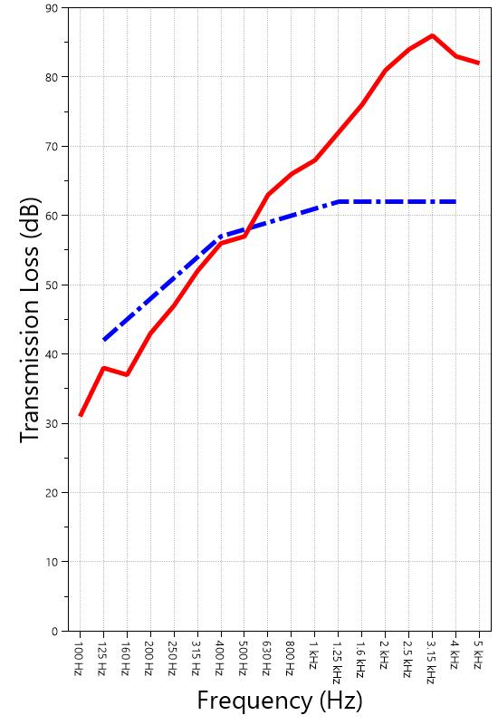
627 RIVERBANK DRIVE GENEVA, IL 60134 630-232-0104
University of Oregon RAL™-TL24-338 2024-07-25
APPENDIX A: Extended Frequency Range Data
Page 15 of 18
Specimen: Marmoleum Decibel adhered with Sustain 1195, 1” Maxxon gypcrete 2000 Multifamily, Certainteed MemBrain vapor retarder, 3” of 3/8” limestone chip, Hempitecture 2” hemp fiber board, Vaagen Timbers 5-ply CLT 6.875” with plywood spline 3/4”x6” at the joint secured with #9x3” screws at 6” OC (See Full Report)
The following non-accredited data were obtained in accordance with ASTM E90-09 (2016), but extend beyond the defined frequency range of 100Hz to 5,000Hz. These unofficial results are representative of the RAL test environment only and intended for research & comparison purposes. Sampling precision observed during this procedure is reported below. Corrections are detailed in Appendix B.
627 RIVERBANK DRIVE GENEVA, IL 60134
630-232-0104
University of Oregon RAL™-TL24-338 2024-07-25 Page 16 of 18
Specimen: Marmoleum Decibel adhered with Sustain 1195, 1” Maxxon gypcrete 2000 Multifamily, Certainteed
MemBrain vapor retarder, 3” of 3/8” limestone chip, Hempitecture 2” hemp fiber board, Vaagen Timbers 5-ply CLT 6.875” with plywood spline 3/4”x6” at the joint secured with #9x3” screws at 6” OC (See Full Report)
Mark Interpretation
A Measured sound pressure levels in the receive room are within 10 dB of the ambient noise level at the marked frequency band. Receive room levels used to calculate Transmission Loss are corrected according to ASTM E90 Section 10.3.
AA Measured sound pressure levels in the receive room are within 5 dB of the ambient noise level at the marked frequency band. Receive room levels used to calculate Transmission Loss are corrected according to ASTM E90 Section 10.3.1. Transmission Loss values calculated from levels corrected this way will be less than or equal to Transmission Loss values from a hypothetical test using the same specimen and a receive room with idealized ambient sound levels of (-∞) dB.
F The reported Transmission Loss is within 10 dB of the laboratory flanking limit at the marked frequency band. The measured performance of the specimen may be limited by the performance of the laboratory building structure at this frequency band.
Z The reported Transmission Loss at the marked frequency band has been corrected according to ASTM E90 Section A3.2.7 to account for possible sound transmission through the filler assembly.
ZZ The reported Transmission Loss at the marked frequency band has been corrected according to ASTM E90 Section A3.2.8 to account for possible sound transmission through the filler assembly. Transmission Loss values corrected this way will be less than or equal to Transmission Loss values from a hypothetical test using the same specimen and an idealized filler assembly with a Sound Transmission Class rating of (∞).
Specimen: Marmoleum Decibel adhered with Sustain 1195, 1” Maxxon gypcrete 2000 Multifamily, Certainteed MemBrain vapor retarder, 3” of 3/8” limestone chip, Hempitecture 2” hemp fiber board, Vaagen Timbers 5-ply CLT 6.875” with plywood spline 3/4”x6” at the joint secured with #9x3” screws at 6” OC (See Full Report)
ΔTL, the 95% confidence interval for reported transmission loss values, is calculated from the standard deviation of the sets of measurements for source room sound pressure level, receive room sound pressure level, and receive room sound absorption. This metric is calculated in an effort to quantify the combined influences of room geometry, microphone positioning, and other varying environmental conditions on reported results.
Repeatability, expressed as a 95% confidence interval, is calculated from the standard deviation of transmission loss as obtained from a set of six (6) consecutive tests conducted according to this test method by RAL from 202102-25 through 2021-03-04. The tests were performed on a specimen composed of a 6 in. thick concrete slab, using the same test opening as used in this report. This metric provides an estimate of the variation in results that might be observed if the test were repeated with no change to the installed specimen. Note that repeatability will vary with the construction type.
627 RIVERBANK DRIVE GENEVA, IL 60134
630-232-0104
1918 BY WALLACE CLEMENT SABINE
University of Oregon RAL™-TL24-338 2024-07-25 Page 17 of 18
APPENDIX D: Determination of Outdoor Indoor Transmission Class (OITC)
Specimen: Marmoleum Decibel adhered with Sustain 1195, 1” Maxxon gypcrete 2000 Multifamily, Certainteed MemBrain vapor retarder, 3” of 3/8” limestone chip, Hempitecture 2” hemp fiber board, Vaagen Timbers 5-ply CLT 6.875” with plywood spline 3/4”x6” at the joint secured with #9x3” screws at 6” OC (See Full Report)
The determination of the Outdoor Indoor Transmission Class (OITC) as reported below was made with explicit conformity to the procedures described in the ASTM E1332-22 test standard. Test Method ASTM E90-09 (2016) was used to obtain the sound transmission loss data. This rating is based on an average transportation noise source spectrum and an A-weighted sound level reduction, either of which may be inappropriate for some applications.
One-third Octave Band Center Frequency, Hz Reference Sound Spectrum, dB Test Specimen
OITC = 44
627 RIVERBANK DRIVE GENEVA, IL 60134 630-232-0104
University of Oregon RAL™-TL24-338 2024-07-25 Page 18 of 18
Specimen: Marmoleum Decibel adhered with Sustain 1195, 1” Maxxon gypcrete 2000 Multifamily, Certainteed MemBrain vapor retarder, 3” of 3/8” limestone chip, Hempitecture 2” hemp fiber board, Vaagen Timbers 5-ply CLT 6.875” with plywood spline 3/4”x6” at the joint secured with #9x3” screws at 6” OC (See Full Report)
Description Model Serial Number Date of Certification Calibration Due
System 2 Type 3160-A-042 3160106974 2023-08-11 2024-08-11
Bruel & Kjaer Mic And Preamp C Type 4943-B-001 2311439 2024-03-29 2025-03-29
Bruel & Kjaer Sound Level
Calibrator Type 4230 861609 2023-12-20 2024-12-20
EXTECH Hygro 663 SD700 A083663 2023-12-28 2024-12-28
EXTECH Hygro 639 SD700 A.103639 2023-12-01 2024-12-01
Specimen: Marmoleum Decibel adhered with Sustain 1195, 1” Maxxon gypcrete 2000 Multifamily, Certainteed MemBrain vapor retarder, 3” of 3/8” limestone chip, Hempitecture 2” hemp fiber board, Vaagen Timbers 5-ply CLT 6.875” with plywood spline 3/4”x6” at the joint secured with #9x3” screws at 6” OC (See Full Report)
Date Revision
2024-07-31 Original report issued
2024-09-17 Page 18: Calibrator added to instruments of traceability -EPW